
Subscribe to Our Youtube Channel
Related Manuals for Arbor Technology FPC-7800 Series


Summary of Contents for Arbor Technology FPC-7800 Series
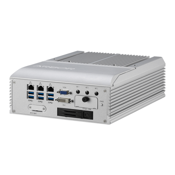
- Page 1 FPC-7800 Series Robust Box PC with 4 Generation Intel Core™ i7/i5/i3 Haswell Platform ® User’s Manual Version 1.0 2015.08 P/N: 4012780000100P...
- Page 2 This page is intentionally left blank. - 2 -...
- Page 3 Revision History Version Release Time Description 2015 August Initial release - i -...
-
Page 4: Table Of Contents
Contents Contents Revision History ................i Contents ..................ii Preface.................... v Copyright Notice.................. v Declaration of Conformity..............v CE ....................v FCC Class A ................v RoHS ...................vi SVHC / REACH ................vi Important Safety Instructions .............vii Warning .....................viii Replacing Lithium Battery ..............viii Technical Support................viii Warranty ....................ix Chapter 1 - Introduction .............. -
Page 5: Contents
Contents 4.1.5. Install SATA Storage Devices .......... 51 4.1.6. Install PCI and PCI Express Cards ......... 57 4.1.7. Install/uninstall CFast Card ..........60 4.1.8. Install/uninstall SIM Card ..........62 4.1.9. Install Wireless Modules ..........64 4.2. Mount the Computer ..............65 4.3. - Page 6 This page is intentionally left blank. - iv -...
-
Page 7: Preface
Preface Preface Copyright Notice All Rights Reserved. The information in this document is subject to change without prior notice in order to improve the reliability, design and function. It does not represent a commitment on the part of the manufacturer. Under no circumstances will the manufacturer be liable for any direct, indirect, special, incidental, or consequential damages arising from the use or inability to use the product or documentation, even if advised of the possibility of such... -
Page 8: Rohs
(PBDE) in electrical and electronic products. Member states of the EU are to enforce by 7/1/2006. ARBOR Technology Corp. hereby states that the listed products do not contain unintentional additions of lead, mercury, hex chrome, PBB or PBDB that exceed a maximum concentration value of 0.1% by weight or for cadmium exceed... -
Page 9: Important Safety Instructions
Preface Important Safety Instructions Read these safety instructions carefully Read all cautions and warnings on the equipment. Place this equipment on a reliable surface when installing. Dropping it or letting it fall may cause damage Make sure the correct voltage is connected to the equipment. For pluggable equipment, the socket outlet should be near the equipment and should be easily accessible. -
Page 10: Warning
Preface Warning The Box PC and its components contain very delicately Integrated Circuits (IC). To protect the Box PC and its components against damage caused by static electricity, you should always follow the precautions below when handling it: Disconnect your Box PC from the power source when you want to work on the inside. -
Page 11: Warranty
Preface Warranty This product is warranted to be in good working order for a period of one year from the date of purchase. Should this product fail to be in good working order at any time during this period, we will, at our option, replace or repair it at no additional charge except as set forth in the following terms. - Page 12 This page is intentionally left blank. - x -...
-
Page 13: Chapter 1 - Introduction
Chapter 1 Introduction Chapter 1 - Introduction - 1 -... -
Page 14: The Computer
Introduction 1.1. The Computer • Fanless Design • Wide Range DC Power Input (9~36V) • iAMT supported • Three Independent Display (DVI-I + DisplayPort x 2) supported • Optional WiFi or HSUPA Wireless Connectivity supported • Rugged Design for Shock / Vibration Protection •... -
Page 15: Specifications
Introduction 1.3. Specifications System Kernel generation Intel Core i7/i5/i3 or Haswell Processor in ® ™ Processor LGA1150 socket BIOS AMI UEFI BIOS Chipset Intel ® Graphics Integrated Intel HD 4600 ® 2 x 204-pin DDR3 SO-DIMM sockets, supporting 1600MHz System Memory SDRAM up to 16GB Serial ATA 2 x Serial ATA ports with RAID 0/1 support... - Page 16 Introduction Storage 2 x 2.5” drive bays Type 1 x CFast slot Qualification Certification CE, FCC Class A Environment Operating Temp. -20 ~ 55°C (-4 ~ 131°F), ambience w/ air flow Storage Temp. -40 ~ 85°C (-40 ~ 185°F) Operating Humidity 10 ~ 95% @ 55°C (non-condensing) Vibration 3 Grms/5 ~ 500Hz/random operation w/ SSD...
-
Page 17: Inside The Package
1.4. Inside the Package Upon opening the package, carefully inspect the contents. If any of the items is missing or appears damaged, contact your local dealer or distributor. The package should contain the following items: 1 x FPC-7800 Series Robust System FPC-7800 FPC-7801/7802/7803 1 x Driver CD 1 x User’s Manual... -
Page 18: Ordering Information
Introduction 1.5. Ordering Information FPC-7800 Fanless system w/o expansion bus FPC-7801 Fanless system w/ 1 x PCI and 1 x PCIe x16 FPC-7802 Fanless system w/ 1 x PCIe x8 and 1 x PCIe x16 FPC-7803 Fanless system w/ 2 x PCI 1.5.1. -
Page 19: Configure-To-Order Service
Introduction 1.5.2. Configure-to-Order Service Make the computer more tailored to your needs by selecting one or more components from the list below to be fabricated to the computer. 80GB SSD Intel 2.5” 80GB SATAIII SSD kit ® HSPA-SI1400 HSUPA 3.75G module kit & internal wiring WIFI-AT2300 Atheros AR9462 Wi-Fi module w/ 20cm internal wiring ANT-H11... - Page 20 This page is intentionally left blank. - 8 -...
-
Page 21: Chapter 2 - System Overview
Chapter 2 System Overview Chapter 2 - System Overview - 9 -... -
Page 22: Dimensions
System Overview 2.1. Dimensions The following illustration shows the dimensions of each FPC-7800 and FPC-7801/7802/7803, with the measurements in width, depth, and height called out. 2.1.1. FPC-7800 6.00 238.00 250.00 225.00 ANT. 1 ANT. 2 ANT. 3 WWAN POWER RESET WLAN Unit:mm CFast / SIM... -
Page 23: Fpc-7801/7802/7803
System Overview 2.1.2. FPC-7801/7802/7803 6.00 238.00 250.00 225.00 ANT. 1 ANT. 2 ANT. 3 WWAN POWER RESET WLAN CFast / SIM Unit:mm - 11 -... -
Page 24: Take A Tour
System Overview 2.2. Take A Tour The computer has some I/O ports, status LED lights and controls on the front and rear panels. The following illustrations show all the components called out for all FPC-7800 and FPC-7801/7802/7803. 2.2.1. Front Views •... - Page 25 • FPC-7801/7802/7803 Front ⑪ ⑫ ① ② ③ ⑩ ⑨ ⑧ ⑦ ⑥ ⑤ ④ Description Description ① ⑧ LAN ports WLAN Link LED ② ⑨ CFast/SIM slots Power LED ③ ⑩ Antenna hole HDD/SSD LED ④ ⑪ Power button Antenna hole ⑤...
-
Page 26: Rear Views
2.2.2. Rear Views Take a look at the rear sides of FPC-7800 and FPC-7801/7802/7803. • FPC-7800 Rear DIO/LPT (Selectable) DisplayPorts Line out DC-in Mic in DVI-I COM Ports • FPC-7801/7802/7803 Rear COM Ports DIO/LPT DisplayPorts Line out (Selectable) DVI-I Mic in DC-in PCI/PCIe slots - 14 -... -
Page 27: Driver Installation Notes
2.3. Driver Installation Notes The FPC-7800 Series support the operating systems of Windows 7, Windows 8 and Linux. For Windows O.S., find the necessary device drivers on the CD that comes with your purchase. For different O.S., the installation of drivers/ utilities may vary slightly, but generally they are similar. - Page 28 System Overview Windows 8 Driver Path Chipset \\Chipset\Windows\v10.0.13\SetupChipset.exe USB 3.0 \USB3.0\ (Setup.exe) \\ME\ME_9.0.13.1402\ Setup.exe 32Bit \\Graphic\WIN7_WIN8\32 Bit\Win32_15367.exe 64Bit \\Graphic\WIN7_WIN8\64 Bit\Win64_15367.exe 32Bit \\Eithernet\Win8-32bit\PROWin32.exe 64Bit \\Eithernet\Win8-64bit\PROWinx64.exe 32Bit \\AUDIO\WIN7_WIN8\32bit\32bit_Win7_Win8_Win81_R275.exe Audio 64Bit \\AUDIO\WIN7_WIN8\64bit\64bit_Win7_Win8_Win81_R275.exe \\AHCI\32\Intel_RST_F6_floppy_Installer_Win7_Win8_ 32Bit v12.9.0.1001 AHCI \\AHCI\64\Intel_RST_F6_floppy_Installer_Win7_Win8_64_ 64Bit v12.9.0.1001 - 16 -...
-
Page 29: Chapter 3 - System Configuration
Chapter 3 System Configuration Chapter 3 - System Configuration - 17 -... -
Page 30: Board Layout
Engine of the Computer 3.1. Board Layout The main board FMB-i87Q1 forms the engine of the FPC-7800 Series computers. This section will provide an thorough view of this board. FMB-i87Q1: Board Top PC17 - 18 -... - Page 31 Engine of the Computer FMB-i87Q1: Board Bottom - 19 -...
-
Page 32: Jumpers, Connectors
Engine of the Computer 3.2. Jumpers, Connectors The main board FMB-i87Q1 comes with some connectors to join cables to other devices and some jumpers and DIP switches to alter hardware configuration. The following in this chapter will explicate each of the components one-by-one. - Page 33 Engine of the Computer JATX1 Board Top Function: AT/ATX MODE Selection Jumper Type: Onboard 2.00mm pitch 1x3-pin header PC17 Setting: Description Setting AT Mode ATX mode (default) - 21 -...
- Page 34 Engine of the Computer JTERM1 Description: COM1 RS422 & RS485 Terminator Selector Jumper Type: Onboard 2.00mm pitch PC17 2x3-pin header Description RS-485 Normal Mode RS-485 120 ohm Terminal Mode 1-3, RS-422 Normal Mode (default) 3-5, RS-422 120 ohm Terminal Mode JTERM2 Description: COM2 RS422 &...
-
Page 35: Connectors
Engine of the Computer 3.2.2. Connectors SATA1 & SATA2 Description: Serial ATA connectors for storage devices Connector Type: 7-pin Serial ATA connector Description Board Bottom - 23 -... - Page 36 Engine of the Computer PWR1 and PWR2 Description: Power connectors for SATA storage devices Connector Type: 2.54mm-pitch 1x4-pin DIP-type connector Pin Desc. +12V Board Bottom - 24 -...
- Page 37 Engine of the Computer Description: PCI Express MiniCard socket Connector Type: Onboard 0.8mm pitch 52-pin edge card connector Pin Desc. Pin Desc. Pin Desc. Wake 20 W_Disable# 36 USB_D- +3.3V 21 GND 37 GND COEX1 22 PERST# 38 USB_D+ 23 PERn0 39 +3.3V COEX2 24 +3.3V...
- Page 38 Engine of the Computer Description: PCIe MiniCard socket (half-size) Connector Type: Onboard 0.8mm pitch 52-pin edge card connector Pin Desc. Pin Desc. Pin Desc. Wake 20 W_Disable# 36 USB_D- +3.3V 21 GND 37 GND COEX1 22 PERST# 38 USB_D+ 23 PERn0 39 +3.3V COEX2 24 +3.3V...
- Page 39 Engine of the Computer DIO1 Description: Digital I/O connector Connector Type: 25-pin female DB connector Pin Desc. Pin Desc. DIO0 DIO8 DIO1 DIO9 DIO2 DIO10 DIO3 DIO11 DIO4 DIO12 DIO5 DIO13 DIO6 DIO14 DIO7 DIO15 Board Top Rear Panel - 27 -...
- Page 40 Engine of the Computer LPT1 Description: Printer/parallel port connector Connector Type: 25-pin female DB connector Desc. Desc. STB# AFD# ERR# INIT# SLIN# ACK# BUSY SLCT Board Top Rear Panel - 28 -...
- Page 41 Engine of the Computer PWRIN1 Description: DC-in power receptacle 1 2 3 4 Connector Type: 5.00mm-pitch 4-pole Euro-Type terminal block Pin Desc. VIN+ VIN- Switch - Switch + Board Top PC17 Rear Panel Optional COM2 COM4 DISPLAYPORT DC IN COM1 COM3 DVI-I DISPLAYPORT...
- Page 42 Engine of the Computer FAN1 Description: CPU fan power connector (The fan must be a +12V fan.) Connector Type: 2.54mm-pitch 1x3-pin wafer connector with one wall Pin Desc. +12V Board Top PC17 - 30 -...
- Page 43 Engine of the Computer DVI-I Description: DVI-I port (digital and analog) Connector Type: 29-pin DIP-type female connector Pin Desc. Pin Desc. Pin Desc. T.M.D.S DATA 2- T.M.D.S DATA 1/3 SHIELD T.M.D.S DATA 5+ T.M.D.S DATA 2+ T.M.D.S DATA 3- T.M.D.S CLOCK SHIELD T.M.D.S DATA 2/4 SHIELD T.M.D.S DATA 3+ T.M.D.S CLOCK+...
- Page 44 Engine of the Computer Description: DisplayPort double stack connectors Connector Type: DisplayPort digital video connector Pin Desc. Pin Desc. LANE_0P LANE_3N LANE_0N LANE_1P LANE_1N COM3_CTS# LANE_2P AUX_N LANE_2N RTN_PWR 10 LANE_3P Board Top Rear Panel - 32 -...
- Page 45 Engine of the Computer JPIC1 Description: PIC programming pin header Connector Type: Onboard 2.0mm pitch 6-pin header Desc. Desc. PIC_TX ICSP-CLK ICSP-DAT VCC5 MCU_RST Board Top PC17 - 33 -...
- Page 46 Engine of the Computer LAN1&LAN2&LAN3 Description: One Ethernet port over double- stacked USB 3.0 ports Connector Type: One 8P8C RJ45 connector w/ two SuperSpeed type-A USB 3.0 connectors 1 2 3 4 LAN (RJ-45) USB (Type-A) Pin Desc. Pin Desc. Pin Desc.
- Page 47 Engine of the Computer USB1 and USB2 Description: Connectors for the internal USB USB2 USB1 ports (for FPC-7801/7802/7803 only, Configure-to-Order) Connector Type: 1 x 5-pin wafer connector USB1 USB2 Pin Desc. Desc. Board Bottom - 35 -...
- Page 48 Engine of the Computer DGP1 Description: External 80 port pin header Connector Type: Onboard 2.0mm pitch 10-pin header USB1 USB2 Pin Desc. Desc. 9 10 FRAME# LAD0 PLTRST# LAD3 LAD2 VCC3 LAD1 Board Bottom PC17 - 36 -...
- Page 49 Engine of the Computer COM1&COM2 Description: Serial port 1&2, configurable between RS232, RS422 and RS485. Connector 9-pin male DB connector Type: Pin Definition: RS232 RS485 RS422 Pin Desc. Pin Desc. Desc. Desc. RS485D- RS422 TX- RS485D+ RS422 TX+ RS422 RX+ RS422 RX- To switch between RS232/422/485 mode, refer to BIOS setting: 5.2.7.
- Page 50 Engine of the Computer COM3&COM4 Description: Serial port 3&4, RS232 ports Connector Type: 9-pin male DB connector Pin Definition: RS232 Desc. Desc. Board Top Rear Panel - 38 -...
-
Page 51: Chapter 4 - Installation And Maintenance
Chapter 4 Installation and Maintenance Chapter 4 - Installation and Maintenance - 39 -... -
Page 52: Install Hardware
Installation & Maintenance 4.1. Install Hardware The FPC-7800 Series is constructed based on modular design to make it easy for users to add hardware or to maintain the computer. The following sections will guide you to the simple hardware installations for the computer. - Page 53 Installation & Maintenance From the front panel, loosen and remove the 2 screws as marked in the illustrations below. (And make sure the CF Card door is closed.) FPC-7800 Front FPC-7801/7802/7803 Front From the rear panel, loosen and remove the 2 screws as marked in the illustrations below.
- Page 54 Installation & Maintenance The inside of the computer comes to view. To adjust jumpers or connect/disconnect cables to/from the main board, 3.2. Jumpers, Connectors on page 20. To install memory modules, see 4.1.2. Install/uninstall Memory Modules on page 46. To install CPU, see 4.1.3.
- Page 55 Installation & Maintenance 4.1.1.2. Remove the Bottom Cover The Serial ATA connectors, the power connectors for SATA storage devices, and the internal USB ports (configure-to-order for FPC-7801/7802/7803 only), PCI and PCIe connectors are all built on the bottom side of the maind board. To access these connectors, the computer’s bottom cover has to go.
- Page 56 Installation & Maintenance From the rear panel, loosen and remove the 2 screws as marked in the illustrations below. FPC-7800 Rear FPC-7801/7802/7803 Rear After the said screws are removed, proceed to dismount the bottom cover. Carefully pry at the joint of the bottom cover and top cover, which locates at about two third of the computer’s height for FPC-7801/7802/7803 and about four fifth of the computer for FPC-7800.
- Page 57 Installation & Maintenance FPC-7803 FPC-7800 2 x PCI To install internal USB drives, see 4.1.4 Install Internal USB Drives page 50. To install SATA storage devices, see 4.1.5. Install SATA Storage Devices on page 51. To install PCI/PCIe cards, see 4.1.6.
-
Page 58: Install/Uninstall Memory Modules
The main board has two dual inline memory module (DIMM) sockets. Increase memory capacity to make programs run faster on the system. The memory module for the FPC-7800 Series’ SO-DIMM sockets should be a 204-pin DDR3 with a “key notch” off the centre among the pins, which enables the memory module for particular applications. - Page 59 Installation & Maintenance Pull back both latches from the socket. the break latch latch the SO-DIMM socket’s slot connector vertical-type SO-DIMM socket (overview) Confront the memory module’s edge connector side at the SO-DIMM socket. Position the memory module at the SO-DIMM socket, with the memory module’s key notch aligned at the break of the SO-DIMM’s slot connector.
-
Page 60: Install Cpu
Installation & Maintenance 4.1.3. Install CPU Remove the top cover from the computer as described in 4.1.1.1. Remove Top Cover on page 40. Locate the CPU socket on the main board The LGA1150 processor socket comes with a lever to secure the processor. Please refer to the pictures step by step as below and note that the cover of the LGA1155 socket must always be installed during transportation to avoid damage to the socket. - Page 61 Installation & Maintenance Find the Heat sink in the accessory box. Attach the thermal gels to the heatsink, and remove the blue release liner. Make sure that heat sink putting on the CPU’s top surface is in complete contact to avoid overheating problem. If not, it would cause your system or CPU hanged, unstable or damaged.
-
Page 62: Install Internal Usb Drives
Installation & Maintenance 4.1.4 Install Internal USB Drives Since some critical application programs rely on a USB key to run, an USB drive is necessary to store related encrypted keys and digital certificates. The FPC-7801, FPC-7802 and FPC-7803 allow building two USB ports inside the chassis to support two USB drives to work therein for reinforced protection against theft or tamper. -
Page 63: Install Sata Storage Devices
Installation & Maintenance 4.1.5. Install SATA Storage Devices The computer supports two 2.5” SATA storage devices to work inside the computer for RAID. The following will gudie you to install two SATA HDD or SSD. 4.1.5.1. Install SATA Storage Devices for FPC-7800 Remove the bottom cover from the computer as described in 4.1.1.2. - Page 64 Installation & Maintenance Fix the storage device in place by using screws at the four screw holes on both sides of the bracket. Install the bracket and the storage device back into the computer by refastening the four screws. SATA connectors power connectors for SATA storage...
- Page 65 Installation & Maintenance Install the bracket and the storage device back into the computer by refastening the three screws. SATA connectors power connectors for SATA storage devices Restore the bottom cover to the computer. - 53 -...
- Page 66 Installation & Maintenance 4.1.5.2. Install SATA Storage Devices for FPC-7801, 7802 & 7803 Remove the bottom cover from the computer as described in 4.1.1.2. Remove the Bottom Cover on page 43. Find the HDD/SSD bracket inside the computer. Loosen and remove the four screws as marked in the picture below.
- Page 67 Installation & Maintenance Slide another HDD/SSD storage device into the bracket. Fix another storage device in place by using screws at the four screw holes on both sides of the bracket. the bracket and two 2.5” SATA storage devices piggybacking. Reinstall the bracket (with the storage devices) to the computer.
- Page 68 Installation & Maintenance Connect the SATA signal cable(s) and power cable(s). Restore the bottom cover to the computer. - 56 -...
-
Page 69: Install Pci And Pci Express Cards
Installation & Maintenance 4.1.6. Install PCI and PCI Express Cards The FPC-7801 supports one PCIe x16 slot and one PCI slot while the FPC- 7802 features each PCIe x16 slot and PCIe x8 slot. And the FPC-7803 comes with two PCI slots. Follow the guide below to install an PCI Express or PCI card to the computer. - Page 70 Installation & Maintenance FPC-7803 2 x PCI 2 x PCI Loosen and remove either of the screws as marked in the illustration below depending on which card to install, a PCI or a PCI Express one. FPC-7801 FPC-7802 PCI PCIex16 PCIex16 PCIex8 FPC-7803...
- Page 71 Installation & Maintenance After the screw is removed, dismount the card door from the I/O bracket. FPC-7801 FPC-7802 card door removed card door removed PCIex16 PCIex16 FPC-7803 card door removed 2 x PCI Plug the PCI or PCI Express card to the due slot. Re-fasten the screw to fix the card in place.
-
Page 72: Install/Uninstall Cfast Card
Installation & Maintenance 4.1.7. Install/uninstall CFast Card The computer supports a CFast card for storage and comes with an outside- accessible CFast slot. Follow through the guide below to install a CFast card to the computer. Note: Be sure to turn off the computer before installing or uninstalling the CF card if the OS is installed on the card. - Page 73 Installation & Maintenance Position the CFast card at the slot as directed by the graphic printed on the inner side of the door. Push-insert the CFast card. Push-insert the CFast card. To uninstall the CFast card: Loosen and remove the card door screw and open the card door. Push-eject the CFast card.
-
Page 74: Install/Uninstall Sim Card
Installation & Maintenance 4.1.8. Install/uninstall SIM Card The computer supports a SIM card for mobile networking and comes with an outside-accessible SIM card slot. Follow through the guide below to install a SIM card to the computer. To install the SIM card: From the front panel of the computer, find the door to the SIM card slot. - Page 75 Installation & Maintenance Position the SIM card at the slot as directed by the graphic printed on the inner side of the door. Push-insert the SIM card. Push-insert the SIM card. To uninstall the SIM card: Loosen and remove the card door screw and open the card door. Push-eject the SIM card.
-
Page 76: Install Wireless Modules
Installation & Maintenance 4.1.9. Install Wireless Modules The computer comes with two Mini-card sockets to load the computer with the wireless modules of PCI Express Mini-card form factor. The configure- to-order wireless modules available with the computer are the 3G module HSPA-SI1400 and the Wi-Fi moldue WIFI-AT2300: HSPA-SI1400 HSUPA 3.75G module kit &... -
Page 77: Mount The Computer
Installation & Maintenance 4.2. Mount the Computer Integrate the computer to where it works by mounting it to a wall in the surroundings. Such integration relies on a wall-mount kit, which is available on option. Follow through the guide below to assemble the kit to the computer: Place the computer upside down on a flat surface. -
Page 78: Ground The Computer
Installation & Maintenance 4.3. Ground the Computer Follow the instructions below to ground the computer to land. Be sure to follow every grounding requirement in your place. Warning Whenever the unit is installed, the ground connection must always be made first of all and disconnected lastly. See the illustration below. -
Page 79: Wire Dc-In Power Source
4.4. Wire DC-in Power Source Warning Only trained and qualified personnel are allowed to install or replace this equipment. Follow the instructions below for connecting the computer to a DC-input power source. Before wiring, make sure the power source is disconnected. Find the terminal block in the accessory box. - Page 80 This page is intentionally left blank. - 68 -...
-
Page 81: Chapter 5 - Bios
Chapter 5 BIOS Chapter 5 - BIOS - 69 -... - Page 82 BIOS The BIOS Setup utility for the FPC-7800 Series is featured by American Megatrends Inc to configure the system settings stored in the system’s BIOS ROM. The BIOS is activated once the computer powers on. When the computer is off, the battery on the main board supplies power to BIOS RAM.
- Page 83 BIOS Key Commands The BIOS Setup utility relies on a keyboard to receive user’s instructions. Hit the following keys to navigate within the utility and use the utility. Keystroke Function ← → Moves left/right between the top menus. ↓ ↑ Moves up/down between highlight items.
-
Page 84: Main
BIOS 5.1. Main The Main menu features the settings of System Date and System Time and displays some BIOS info. Aptio Setup Utility - Copyright (C) 2015 American Megatrends, Inc. Main Advanced Chipset Boot Security Save & Exit BIOS Information Choose the system default BIOS Vendor American Megatrends... -
Page 85: Advanced
BIOS 5.2. Advanced Access the Advanced menu to manage the computer’s system configuration including the Super IO chip, Fintek 81866. Aptio Setup Utility - Copyright (C) 2015 American Megatrends, Inc. Main Advanced Chipset Boot Security Save & Exit ACPI Settings System ACPI Parameters S5 RTC Wake Settings CPU Configuration... - Page 86 BIOS 5.2.10. Intel Ethernet Network Connection i217-LM Intel(R) Ethernet Network Connection I217-LM on page Intel(R) I210 Gigabit 5.2.11. Intel I210 Gigabit Network Connection Network Connection page - 74 -...
-
Page 87: Acpi Settings
BIOS 5.2.1. ACPI Settings The submenu ACPI Settings enable users to change the system’s ACPI (Advanced Configuration and Power Interface) configuration by the following settings: Aptio Setup Utility - Copyright (C) 2015 American Megatrends, Inc. Main Advanced Chipset Boot Security Save & Exit ACPI Settings Enables or Disables System ability to Hibernate (OS/S4... -
Page 88: Ss Rtc Wake Settings
BIOS 5.2.2. SS RTC Wake Settings Access this submenu to configure whether and when to awake the system. Aptio Setup Utility - Copyright (C) 2015 American Megatrends, Inc. Advanced Wake system with Fixed Time [Disabled] Enable or disable System wake on alarm [Disabled] event. -
Page 89: Cpu Configuration
BIOS Sets if to awake the system some time in the future. Options available are Enabled and Disabled (default). Enable this feature to awake the system some time from Wake System now. When enabled, the following setting becomes available: with Dynamic Setting Description TIme... -
Page 90: Sata Configuration
BIOS 5.2.4. SATA Configuration SATA Configuration manages the system’s SATA configuration and also delivers its status. Aptio Setup Utility - Copyright (C) 2015 American Megatrends, Inc. Advanced Enable or disable SATA Device. SATA Controller(s) [Enabled] SATA Mode Selection [AHCI] Software Feature Mask Configuration Serial ATA Port 0 INTEL SSDSC2BB (80.0G Software Preserve... -
Page 91: Amt Configuration
BIOS 5.2.5. AMT Configuration Intel Active Management Technology (Intel AMT) is a hardware-based solution ® ® that uses out-of-band communication for system administrators to monitor and manage the computers and other network equipment by remote control even if the hard drive is crashed, the system is turned off or the operating system is locked. -
Page 92: Usb Configuration
BIOS 5.2.6. USB Configuration Select this submenu to view the status of the USB devices and configure USB features. Aptio Setup Utility - Copyright (C) 2015 American Megatrends, Inc. Advanced USB Configuration Enables Legacy USB support. AUTO option disables legacy support if no USB devices are connected. - Page 93 BIOS USB Mass Storage Enables/disables USB Mass Storage Driver Support. Driver Support The optional settings are: Disabled / Enabled. This is a submenu to configure the features of USB hardware delay and time-out. The featured settings are: Setting Description Use this item to set the time-out value USB Transfer for control, bulk, and interrupt transfers.
-
Page 94: F81866 Super Io Configuration
BIOS 5.2.7. F81866 Super IO Configuration This submenu configures the Super IO chip (Fintek F81866) for the computer’s serial ports 1~4 and the parallel port. The featured submenus are: Aptio Setup Utility - Copyright (C) 2015 American Megatrends, Inc. Advanced Set Parameters of Serial Port F81866 Super IO Configuration 1 (COMA) - Page 95 BIOS Configures the computer’s COM2, which is configurable between RS232, RS422 and RS485. The featured settings are: Setting Description Serial Port 2 Enables/disables the serial port. Configuration Serial Port Enabled is the default. Select RS232, RS422, and RS485 mode Serial Port 2 RS232 is the default.
-
Page 96: F81866 H/W Monitor
BIOS 5.2.8. F81866 H/W Monitor Select this submenu to view the main board’s hardware status. Select it to run a report of various info as depicted below: Aptio Setup Utility - Copyright (C) 2015 American Megatrends, Inc. Main Advanced Chipset Boot Security Save & Exit PC Health Status System temperature : +50 °C... -
Page 97: Serial Port Console Redirection
BIOS 5.2.9. Serial Port Console Redirection Select this submenu to configure the serial port console redirection configuration. Aptio Setup Utility - Copyright (C) 2012 American Megatrends, Inc. Main Advanced Chipset Boot Security Save & Exit COMO Console Redirection Enable or Console Redirection [Disabled] Disable. - Page 98 BIOS Selects the Data Bits Data Bits 8 is the default. A parity bit can be sent with the data bits to detect some transmission errors. Even: parity bit is 0 if the num of 1’s in the data bits is even. Odd: parity bit is 0 if num of 1’s in the data bits is odd.
- Page 99 BIOS Setting Description Enables/Disables console redirection. Console Disabled is the default. Redirection Following submenu is available only when Console Redirection is set to Enabled. Emulation: ANSI: Extended ASCII char set. VT100: ASCII char set. Terminal VT100+: Extends VT100 to support color, functional keys, etc. Type VT-UTF8: Uses UTF8 encoding to map Unicode chars onto 1 or more bytes...
-
Page 100: Intel Ethernet Network Connection I217-Lm
BIOS 5.2.10. Intel Ethernet Network Connection i217-LM Aptio Setup Utility - Copyright (C) 2015 American Megatrends, Inc. Main Advanced Chipset Boot Security Save & Exit PORT CONFIGURATION MENU Configure Boot Protocal, Wake NIC Configuration [Disabled] on LAN, Link Speed and VLAN. Blink LEDs PORT CONFIGURATION INFORMATION UEFI Driver:... -
Page 101: Intel I210 Gigabit Network Connection
BIOS 5.2.11. Intel I210 Gigabit Network Connection Aptio Setup Utility - Copyright (C) 2015 American Megatrends, Inc. Main Advanced Chipset Boot Security Save & Exit PORT CONFIGURATION MENU Click to configure the network NIC Configuration [Disabled] device port. Blink LEDs (range 0-15 seconds) PORT CONFIGURATION INFORMATION UEFI Driver: Intel(R) PRO/100 5.5.23... -
Page 102: Chipset
BIOS 5.3. Chipset The Chipset menu controls the system’s chipset. Aptio Setup Utility - Copyright (C) 2015 American Megatrends, Inc. Main Advanced Chipset Boot Security Save & Exit PCH-IO Configuration PCH Parameters System Agent (SA) Configuration →←: Select Screen : Select Item Enter: Select +/-: Change Opt. -
Page 103: Pch-Io Configuration
BIOS 5.3.1. PCH-IO Configuration Select this submenu to view the RC version, SKU name and revision ID of the Intel PCH. Select this submenu also to configure the PCH: ® Aptio Setup Utility - Copyright (C) 2015 American Megatrends, Inc. Main Advanced Chipset... - Page 104 BIOS 5.3.1.1. PCI Express Configuration Configures PCI Express by the following settings: Setting Description ASPM Support Options are: Disable : disables ASPM L0s : force all links to L0s state PCI Express Root Port L1 : force all links to L1 state 1/2/3 L0sL1 : force all links to L0s+L1 state Auto : BIOS auto configure...
- Page 105 BIOS PCIe Speed Options are: Auto, Gen 1, Gen 2 Auto is the default. Detect Non-Compliance Device If enable, system will spend more time at POST Extra Bus Reserved Configure Extra Bus Reserved (0-7) for bridge behind this Root bridge. Reserved Memory Configure Reserved Memory Range this Root bridge.
- Page 106 BIOS 5.3.1.2. USB Configuration Access this submenu to configure the system’s USB ports. The featured settings are: Setting Description Precondition work on USB host controller and root ports for faster enumeration. USB Precondition Options available are: Enabled/Disabled. Disabled is the default. Configures how the xHCI controller works.
-
Page 107: System Agent (Sa) Configuration
BIOS 5.3.2. System Agent (SA) Configuration Select this submenu to view the name and RC version of the System Agent (SA), i.e. the north bridge. Select this submenu also to configure the System Agent (SA) by the following setting and submenus: Aptio Setup Utility - Copyright (C) 2015 American Megatrends, Inc. - Page 108 BIOS 5.3.2.1. Graphics Configuration Select Graphics Configuration to view graphics info and accesses graphics settings. The featured settings are: Setting Description IGFX VBIOS Version Display the IGFX(internal VGA) VBIOS version. IGFX Frequency Display the IGFX freqency Sets the graphics turbo IMON current values. Graphics Turbo IMON Options available are 14 to 31.
- Page 109 BIOS 5.3.2.2. NB PCIe Configuration Access this submenu to configure the system’s PCIe. Setting Description PEG0 Display the PEG0 status. PEG0-Gen X Configure the PEG0 Options available are Auto/Gen1/Gen2/Gen3. Auto is the default. PEG1 Display the PEG1 status. PEG1-Gen X Configure the PEG1 Options available are Auto/Gen1/Gen2/Gen3.
-
Page 110: Boot
BIOS 5.4. Boot The Boot menu configures how to boot up the system such as the configuration of boot device priority. Aptio Setup Utility - Copyright (C) 2015 American Megatrends, Inc. Main Advanced Chipset Boot Security Save & Exit Boot Configuration Number of seconds to wait for Setup Prompt Timeout setup activation key. -
Page 111: Csm Paramenters
BIOS Boot Option Priority Set the legacy device, hard-drive boot priorities. Boot Option Priority Set the legacy device, floopy drive boot priorities. Configures whether to launch the UEFI/legacy OpROM, boot options, filters, etc. See the full settings at 5.4.1. CSM CSM parameters Paramenters on page... - Page 112 BIOS Defines the devices to boot the system to. Options available are UEFI and Legacy (default), Legacy Boot Option only and UEFI only. Filter This setting is only available when Launch CSM is enabled (set to Always). Configures whether to launch the UEFI or legacy OpROM of PXE (Preboot eXecution Environment).
-
Page 113: Security
BIOS 5.5. Security The Security menu sets up the password for the system’s administrator account. Once the administrator password is set up, this BIOS Setup utility is limited to access and will ask for the password each time any access is attempted. -
Page 114: Save & Exit
BIOS 5.6. Save & Exit The Save & Exit menu features a handful of commands to launch actions from the BIOS Setup utility regarding saving changes, quitting the utility and recovering defaults. Aptio Setup Utility - Copyright (C) 2015 American Megatrends, Inc. Main Advanced Chipset Boot Security Save &... -
Page 115: Appendices
Appendices Appendices - 103 -... -
Page 116: A: Digital I/O Setting
Appendices A: Digital I/O Setting Digital I/O can read from or write to a line or an entire digital port, which is a collection of lines. This mechanism helps users achieve various applications such as industrial automation, customized circuit, and laboratory testing. Take the source code below that is written in C for the digital I/O application example. - Page 117 Appendices outportb(sioIndex,0x27); Bank select - GPIO0 */ iTemp = inportb(sioData); outportb(sioData, iTemp & 0xFA ); outportb(sioIndex,0x2C); GPIO0 Enable */ outportb(sioData, 0x1F); outportb(sioIndex,0x07); Select logic device – GPIO */ outportb(sioData, 0x06); outportb(sioIndex,0x30); Enable GPIO */ outportb(sioData, 0x01); iTemp = iMode & 0x00FF; outportb(sioIndex,0xA0); GPIO 50~57 - Output Enable */ outportb(sioData,iTemp); iTemp = (iMode & 0xFF00) >> 8; outportb(sioIndex,0xF0); GPIO 00~07 - Output Enable */ outportb(sioData,iTemp); outportb(sioIndex,0xAA); /* Disable Super I/O */ void SioGPIOData(int iData) int iTemp;...
- Page 118 Appendices outportb(sioIndex,0xAA); /* Disable Super I/O */ int SioGPIOStatus() int iStatus; int iTemp; outportb(sioIndex,0x87); Enable Super I/O */ outportb(sioIndex,0x87); outportb(sioIndex,0x07); Select logic device – GPIO */ outportb(sioData, 0x06); outportb(sioIndex,0xA2); GPIO 50~57 - Status */ iTemp = inportb(sioData); outportb(sioIndex,0xF2); GPIO 00~07 - Status */ iStatus = inportb(sioData); outportb(sioIndex,0xAA); /* Disable Super I/O */ iStatus = (iStatus<<8) + iTemp; return iStatus;...
-
Page 119: B: Watchdog Timer (Wdt) Setting
Appendices B: Watchdog Timer (WDT) Setting WDT is widely used for industry application to monitor the activity of CPU. Application software depends on its requirement to trigger WDT with adequate timer setting. Before WDT time out, the functional normal system will reload the WDT. -
Page 120: C: 3G Module Hspa-Si1400 Hardware/Software Installation
Appendices C: 3G Module HSPA-SI1400 Hardware/Software Installation To be able to network with 3G, hardware-wise the computer needs a 3G module installed and a SIM card inserted (as described in 4.1.8. Install/uninstall on page 62) and software-wise the computer needs the device SIM Card driver and an application program. - Page 121 Appendices Have the HSPA-SI1400 3G module kit. The 3G module is a full-size module of PCI Express Mini-card form factor, with two U.FL connectors, one is “MAIN“, and the other is “AUX“. Two U.FL connectors, one is “MAIN”, the other is “AUX”.
- Page 122 Appendices Remove the plastic plug from the enclosure’s front panel to make an antenna hole. Keep the plastic plug for any possible restoration in the future. Have the RF antenna. The antenna has an SMA connector on one end and an MHF connector on the other. SMA connector MHF connector - 110 -...
- Page 123 Appendices Connect the RF antenna’s MHF connector to the 3G module’s “MAIN“ connector. Connect the RF antenna’s MHF connector to the 3G module’s “MAIN” connector. From the other end of the RF antenna, which is an SMA connector, remove the washer and the nut. Save the washer and nut for later use. Note the SMA connector has the form of a threaded bolt, with one flattened side.
- Page 124 Appendices Pull the SMA connector through the above mentioned antenna hole. Note to meet the aforesaid flattened side with the antenna hole's flat side. the flat side of the antenna hole Arrange the flat side of the SMA connector to meet the flat side of the antenna hole.
- Page 125 Appendices 12. Have an external antenna. Screw and tightly fasten the antenna to the SMA connector. 13. Swivel the antenna to an angle of best signals. - 113 -...
-
Page 126: Install Device Driver
Appendices C.2. Install Device Driver As described in 2.3. Driver Installation Notes on page 15, after the drivers for the chipset, .NET Framework, audio and Ethernet are installed, you can proceed to install the driver for the wireless modules such as 3G module or Wi-Fi module. - Page 127 Appendices Click the Next button to proceed. The driver installation then starts, progresses and finishes. Click the Finish button to quit the driver installation. - 115 -...
-
Page 128: Install Application Program
Appendices C.3. Install Application Program Request a copy of the application program from ARBOR customer service by the contact info as described in Technical Support on page viii. Run the Windows Installer file Watcher_Generic.msi. The installer opens and prepares to install. Once the preparation finishes, the installer prompts to install Sierra Wireless AirCard Watcher on the computer. - Page 129 Appendices Click the Next button to proceed. The installer then prompts the license agreement. Select I accept the terms in the license agreement. Click the Change... button to browse for an alternate folder to install the application program to, or simply click the Next button to install the application program to the suggested folder.
- Page 130 Appendices An AirCard Watcher icon then shows up on the desktop. Double-click the AirCard Watcher icon to launch the application program. The AirCard Watcher opens. See the document of the AirCard Watcher to know how to use the application program. - 118 -...
-
Page 131: D: Wi-Fi Module Wifi-At2300 Hardware Installation
Appendices D: Wi-Fi Module WIFI-AT2300 Hardware Installation To use Wi-Fi, hardware-wise the computer needs a Wi-Fi module installed, and software-wise the computer needs the device driver and an application program. This appendix will guide you to install the Wi-Fi module WIFI-AT2300 . - Page 132 Appendices Prepare the WIFI-AT2300 Wi-Fi module kit. The module is a half-size module of PCI Express Mini-card form factor, with two U.FL connectors, one is “MAIN“, and the other is “AUX“. Two U.FL connectors, one is “MAIN”, the other is “AUX”. - 120 -...
- Page 133 Appendices In order to make the half-size Wi-Fi module compatible with the Mini- card socket, extend the WiFi module with a “mini half bracket”. Join them together by using two screws. Position the WiFi Join the WiFi module module and the “mini and the “mini half half bracket”...
- Page 134 Appendices Press down the module and fix the module in place using two screws. Remove the plastic plug from the computer's rear (or front) panel to make an antenna hole. Keep the plastic plug for any possible restoration in the future.
- Page 135 Appendices Have the RF antenna. The antenna has an SMA connector on one end and an MHF connector on the other. SMA connector MHF connector Connect the RF antenna’s MHF connector to the Wi-Fi module’s “MAIN“ connector. Connect the RF antenna’s MHF connector to the Wi-Fi module’s “MAIN”...
- Page 136 Appendices 10. From the other end of the RF antenna, which is an SMA connector, remove the washer and the nut. Save the washer and nut for later use. Note the SMA connector has the form of a threaded bolt, with one flat side. Among the screw Remove thread, there is a...
- Page 137 Appendices 12. Mount the washer first and then the nut to the SMA connector. Make sure the nut is tightened. Mount the washer and the nut to the SMA connector. Tighten the nut. 13. Restore the computer’s top cover. 14. Have an external antenna. Screw and tightly fasten the antenna to the SMA connector.
- Page 138 Appendices 15. Swivel the antenna to an angle of best signals. - 126 -...
Need help?
Do you have a question about the FPC-7800 Series and is the answer not in the manual?
Questions and answers