
Related Manuals for Digital Watchdog DWC-LPR550


Summary of Contents for Digital Watchdog DWC-LPR550
-
Page 1: Bullet Camera
Bullet Camera DWC-LPR550 ABOUT MANUAL Before installing and using the camera, please read this manual carefully. Be sure to keep it handy for future reference. 01/2015... - Page 2 PRECAUTIONS Do not open or modify. Do not open the case except during maintenence and installation, for it may be dangerous and can cause damages. Do not put objects into the unit. Keep metal objects and flammable substances from entering the camera. It can cause fire, short-circuits, or other damages.
-
Page 3: Table Of Contents
Table of Contents TABLE OF CONTENTS Introduction Features Parts and Descriptions Dimensions Installation Inside the Box Mount Installation Instructions LPR Installation Instructions Connecting to Monitors Control Board Adjusting the Camera Angle Module OSD Menu 14-23 Troubleshooting Warranty Information 25-26 Specifications... - Page 4 FEATURES* STAR-LIGHT LPR™ License Plate Recognition Technology captures reflective license plates up to 50mph with a 13’~30’ Capture Range Reliable Performance under Any Lighting Conditions STAR-LIGHT™ Super Low Light Technology External OSD and Lens Adjustment True Day/Night with IR Cut Filter 1/3”...
-
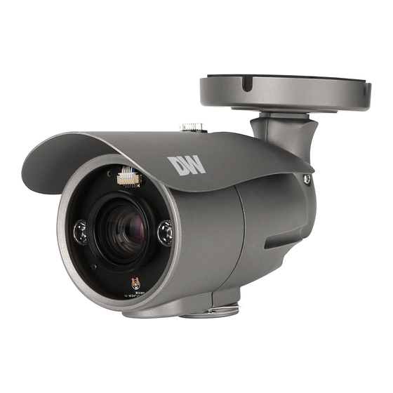
Page 5: Parts And Descriptions
PARTS & DESCRIPTION* Sunshiled Cover Con Cap Zoom Control Mounting Bracket focus Control OSD Joystick Controller Con Cap Test Video Slot Set Screw... -
Page 6: Dimensions
DIMENSIONS IN MILLIMETERS (IN)* 248.0 (2.76”) 131.0 95.0 (5.15”) (3.74”) 226.0 (8.9”) -
Page 7: Inside The Box
Mounting Template L-Key 4 Machine Screws and 4 Dry Wall Anchors Test Monitor Cable Bullet Camera DWC-LPR550 ABOUT MANUAL Before installing and using the camera, please read this manual carefully. Be sure to keep it handy for future reference. 07232013... -
Page 8: Installation Instructions
INSTALLATION INSTRUCTIONS* 1. Using the mounting template or your own camera, mark and drill the necessary holes to mount the bracket to a wall or ceiling. 2. Pull all necessary wires through and make the proper connections. 3. Use the four (4) mounting screws to install the camera on the wall or ceiling. - Page 9 INSTALLATION INSTRUCTIONS* An LPR camera is designed to read a license plate only. When a license plate passes by the camera, the reflective film on the plate will be reflected back to the camera which gives you the good clear shot of the plate. You will ONLY capture an image of the plate. US license plates need to be at least 130 pixels wide.
- Page 10 INSTALLATION INSTRUCTIONS* LPR Camera Installation THE CAMERA SHOULD BE MOUNTED AT AN ANGLE NO GREATER THAN 30 DEGREES 3–8 < 30° CAMERA ANGLE NO GREATER THAN 20 DEGREES FOR SIDE MOUNT INSTALLATIONS < 20°...
-
Page 11: Connecting To Monitors
CONNECTING TO MONITORS* Use the diagram below to connect to a Monitor or CRT Monitor properly. 12VDC/24VAC CCTV Monitor Second Video Output Monitor Power Connection - 12VDC/24VAC Dual Voltage (Auto Polarity Detection and Protection) All cameras are equipped with a second video output for on-site configuration. -
Page 12: Control Board
CONTROL BOARD* Zoom Control focus Control Joystick: Controls the OSD menu. Secondary Connector: Video Output Connector for On-Site Configuration Remove the camera’s lens cover by rotating it counter-clockwise. Use the Joystick to control the camera’s OSD options. -
Page 13: Adjusting The Camera Angle
ADJUSTING THE CAMERA ANGLE* CAUTION : Do not rotate more than 360 Do not unnecessarily twist too many times. -
Page 14: Module Osd Menu
MODULE OSD MENU* EXPOSURE COLOR DAY & NIGHT FUNCTION LENS WB BAL. D&N MODE MIRROR MANUAL / DC NOT USED NOT USED OFF / ON BACKLIGHT CONTROL SHARPNESS COLOR GAIN OFF / BLC / HME NOT USED 0 ~ 20 NOT USED DRC/ DEFOG DELAY... - Page 15 EXPOSURE LENS Manual mode supports the fixed board lens or the Manual manual iris lens. DC mode supports the auto-iris varifocal lens. Brightness: Adjust the camera’s brighness from 0~20. The higher the number, the brighter the image will appear. Shutter: Sets the lens’ shutter speed. This value is set by default to Lens Submenu 1/1000 for optimal license plate capture.
- Page 16 EXPOSURE DYNAMIC RANGE COMPRESSOR This feature is set by default to work with the camera as a license plate capturing camera. Do not change the values. - DEFOG: This feature is set by default to work with the camera as a license plate capturing camera.
- Page 17 COLOR NOT USED This is a License Plate Recognition Camera. As such, it has been programmed specifically to register license plates only. For optimal results, this camera is set to B/W mode only. There is no Color mode on this camera. As a result, White Balance and Color Gain under the Color Menu and Day/Night Mode, Control and Delay options under the Day/Night Menu are not used for this camera.
- Page 18 FUNCTION MIRROR Reflects the camera horizontally. MIRROR Mirror OFF Mirror ON SHARPNESS Sets the image sharpness. The higher the number, the sharper the image. 0 ~ 30 GAMMA Select the desired gamma level. 0.7 is default setting. 0.35 ~ 0.7 POSI / NEGATIVE If NEGATIVE is enabled, the camera’s image OFF / ON...
- Page 19 MOTION The camera can detect the movement and display an alarm on the screen when movement is detected. MOTION Select to enable or disable the camera’s motion detection. If ON is selected: OFF / ON SENSITIV. Sensitivity level of the motion detection is adjustable. Motion Detection will be more 0 ~ 30 sensitive at a higher number.
- Page 20 PRIVACY You can hide some parts of the screen for privacy masking. A total of 8 different privacy masking zones are available. MASK COLOR This is a License Plate Recognition Camera. As such, it has been programmed specifically to register license plates only. For optimal results, this camera is set to B/W mode only.
- Page 21 SETUP TITLE If ON is selected, you can display the camera title on the screen. If enabled, OFF / ON manually enter the camera’s display name using the joystick controller. INTERNAL SYNC. Select whether the camera syncronizes internally or using Line Lock. INT/ COMMUNICATION The Communications settings allow you to setup the camera’s ID, Baudrate, Protocol,...
- Page 22 SETUP LANGUAGE The camera supports the following languages: ENGLISH. FONT COLOR This is a License Plate Recognition Camera. As such, it has been programmed specifically to register license plates only. For optimal results, this camera is set to B/W mode only. There is no Color mode on this camera.
- Page 23 EXIT EXIT SAVE Exit the OSD menu after saving the recent changes. RESTORE Exit the OSD menu without saving recent changes. INITIAL Exit the OSD menu after resetting the camera to factory default.
-
Page 24: Troubleshooting
TROUBLESHOOTING Before sending your camera for repair, check the following or contact our technical specialist. FOR NO VIDEO Check the coaxial cable and make sure it is connected securely. Check the lens’ iris adjustment at the camera’s OSD menu. Check the power supply and make sure the camera has the proper voltage and current. -
Page 25: Warranty Information
WARRANTY INFORMATION* Digital Watchdog (referred to as “the Warrantor”) warrants the Digital Watchdog Camera against defects in materials or workmanship as follows: LABOR: For the initial five (5) years and one (1) year on IR LED from the original purchase date, if the camera is determined to be defective, the Warrantor will repair or replace the unit with a new or refurbished product at its option at no charge. - Page 26 This warranty gives you specific legal rights, and you may also have other rights that vary from state-to-state. If the problem is not handled to your satisfaction, then write to the following address: Digital Watchdog, Inc. ATTN: RMA Department 5436 W. Crenshaw Street...
-
Page 27: Specifications
SPECIFICATIONS* VIDEO Image Sensor and Total Pixels 1/3" 960 CCD Sensor, 960(H) X 478 (V), 520K Scanning System 2 : 1 Interlace Frequency 15.734KHz (H), 59.95Hz (V) Synchronization Internal or Line Lock Horizontal Resolution 700 TV Lines [B/W] Minimum Illumination 0 Lux (F1.2 , 30IRE) at TDN(B/W) S/N Ratio 52dB (AGC off) - Page 28 5436 W Crenshaw St. Tampa, FL 33634 Tel : 866-446-3595 / 813-888-9555 Fax : 813-888-9262 www.Digital-Watchdog.com technicalsupport@dwcc.tv Technical Support Hours : Monday-Friday 9:00am to 8:00pm EST...
Need help?
Do you have a question about the DWC-LPR550 and is the answer not in the manual?
Questions and answers