Gefen EXT-HDMI1.3-444 User Manual
Hide thumbs
Also See for EXT-HDMI1.3-444:
- User manual (17 pages) ,
- User manual (15 pages) ,
- User manual (36 pages)
Table of Contents
Advertisement
Quick Links
Advertisement
Table of Contents

Related Manuals for Gefen EXT-HDMI1.3-444


Summary of Contents for Gefen EXT-HDMI1.3-444
- Page 1 Matrix for HDMI 1.3 EXT-HDMI1.3-444 User Manual Release A7...
-
Page 2: Important Safety Instructions
4x4 Matrix for HDMI 1.3 Important Safety Instructions Read these instructions. Keep these instructions. Heed all warnings. Follow all instructions. Do not use this product near water. Clean only with a dry cloth. Do not block any ventilation openings. Install in accordance with the manufacturer’s instructions. -
Page 3: Warranty Information
Gefen warrants the equipment it manufactures to be free from defects in material and workmanship. If equipment fails because of such defects and Gefen is notified within two (2) years from the date of shipment, Gefen will, at its option, repair or replace the equipment, provided that the equipment has not been subjected to mechanical, electrical, or other abuse or modifications. - Page 4 4x4 Matrix for HDMI 1.3 is a trademark of Gefen, LLC. Important Notice Gefen, LLC reserves the right to make changes in the hardware, packaging, and any accompanying documentation without prior written notice. © 2014 Gefen, LLC. All Rights Reserved.
- Page 5 4x4 Matrix for HDMI 1.3 Operating Notes • Make sure to connect all the cables and the power supply prior to connecting power to the HDMI sources and the 4x4 Matrix for HDMI 1.3. • 3D content will be displayed when using with a 3D compatible source and TV. •...
-
Page 6: Packing List
Packing List The 4x4 Matrix for HDMI 1.3 ships with the items listed below. If any of these items are not present in the box when you first open it, immediately contact your dealer or Gefen. • 1 x Gefen 4x4 Matrix for HDMI •... -
Page 8: Table Of Contents
4x4 Matrix for HDMI 1.3 Table of Contents Getting Started Panel Layout ......................2 Front ......................2 Back ......................3 IR Remote Control Unit ..................4 Front ......................4 Back ......................5 Installing the Battery ..................6 Setting the IR Channel .................. 6 Installation ...................... -
Page 11: 01 Getting Started
Matrix for HDMI 1.3 01 Getting Started Panel Layout ......................2 Front ......................2 Back ......................3 IR Remote Control Unit ..................4 Front ......................4 Back ......................5 Installing the Battery ..................6 Setting the IR Channel .................. 6 Installation ...................... -
Page 12: Panel Layout
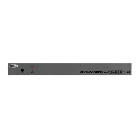
Getting Started Panel Layout Front Name Description IR sensor This IR sensor receives commands from the included IR remote control unit. Power This LED indicator glows bright red when the unit is powered. Reset Press this button to reset the 4x4 Matrix for HDMI 1.3. Input / Output These blue LED indicators display the state of each Indicators... -
Page 13: Back
HDMI cables. 5V DC Connect the included locking 5V DC power supply from this power receptacle to an available AC electrical outlet. Ext IR Connect an IR Extender (Gefen part no. EXT-RMT- EXTIRN) to this port. page | 3... -
Page 14: Ir Remote Control Unit
Getting Started IR Remote Control Unit Front Name Description Activity indicator This LED flashes bright orange when a key is pressed on the remote. Input Selection (1 - 16) Press these buttons to switch the desired input (source) to a specific output. Buttons 1 - 4 are used to select the input for Out 1, buttons 5 - 8 are used to select the input for Out 2, and so on. -
Page 15: Back
Getting Started IR Remote Control Unit Back (shown with cover removed) Name Description DIP switch bank Use these DIP switches to set the IR channel of the remote. See Setting the IR Channel (page 6) for more information. Primary battery slot Holds the battery for operating the remote. -
Page 16: Installing The Battery
Getting Started IR Remote Control Unit Installing the Battery The IR remote control unit ships with two batteries. Only one battery is required for operation. The second battery is a spare. WARNING: Use only 3V CR2032-type batteries. Risk of explosion if battery is replaced by an incorrect type. - Page 17 Getting Started IR Remote Control Unit Consecutively press the Reset button on the front panel of the matrix to cycle through each of the IR channels: LED 1 = channel 1, LED 2 = channel 2, and so on. Set the IR channel on the remote, using the table below. The IR channel for IR remote must match the IR channel of the matrix.
-
Page 18: Installation
OPTIONAL: Connect an RS-232 cable from the RS-232 port on the matrix to the RS-232 connector on the serial controller. OPTIONAL: Connect an IR extender (Gefen part no. EXT-RMT-EXTIRN) to the IR Ext port on the matrix. Connect the included 5V DC locking power supply to the power receptacle on the matrix. -
Page 21: Operating The 4X4 Matrix For Hdmi
Matrix for HDMI 1.3 02 Operating the 4x4 Matrix for HDMI 1.3 Routing Basics ....................12 Determining the Current Routing State ............12 Using the IR Remote Control Unit ............... 13 Using the IR Extender ................. 14 EDID Management ....................15 Selecting the EDID Mode ................ -
Page 22: Routing Basics
Operating the 4x4 Matrix for HDMI 1.3 Routing Basics Determining the Current Routing State The front panel of the matrix has 16 blue LED indicators. Each of these LED indicators is grouped in sets of four. Each set of four LED indicators represents an output, from left to right: Back of matrix Output 1... -
Page 23: Using The Ir Remote Control Unit
Operating the 4x4 Matrix for HDMI 1.3 Routing Basics Using the IR Remote Control Unit The IR remote control unit provides discrete routing between each input and output. There are a total of 16 buttons on the IR remote. The buttons are color-coded in groups of four, which match each group of four LED indicators on the front panel. -
Page 24: Using The Ir Extender
There may be situations where the IR sensor is blocked by a cabinet or other mounting device. In this case, an IR extender (Gefen part no. EXT-RMT-EXTIRN) can be connected to the IR port on the matrix. The sensor on the IR extender behaves exactly like the sensor on the front panel of the matrix. -
Page 25: Edid Management
Operating the 4x4 Matrix for HDMI 1.3 EDID Management The 4x4 Matrix for HDMI 1.3 features EDID Management. Before the source can send video and/or audio to the display (sink), the source reads the EDID (Extended Display Identification Data) from the sink (display) devices that are connected to the matrix. The EDID contains information about what type of audio/video data that the source can send to each output device. -
Page 26: Internal Edid
Operating the 4x4 Matrix for HDMI 1.3 EDID Management Internal EDID Use this EDID mode if problems are encountered when using the external EDID. The built-in internal EDID provides the source device with a “generic” EDID which can be used by all display (sink) devices. Select the internal EDID mode. -
Page 27: External Edid
Operating the 4x4 Matrix for HDMI 1.3 EDID Management External EDID When set to Ext mode, EDID data will be fetched from the sink that is connected to HDMI Out 1. It is recommended that the display with the lowest native resolution be connected to HDMI Out 1. -
Page 29: 03 Advanced Operation
Matrix for HDMI 1.3 03 Advanced Operation RS-232 Configuration ..................20 RS-232 Interface ..................20 RS-232 Settings ..................20 Commands ......................21... -
Page 30: Rs-232 Configuration
Advanced Operation RS-232 Configuration RS-232 Interface DE-9 DA-15 RS-232 Controller Matrix DB-25 Only TXD, RXD, and GND pins are used. DC-37 RS-232 Settings DD-50 Description Setting 19200 Baud rate Data bits None Parity Stop bits None Hardware flow control page | 20... -
Page 31: Commands
Advanced Operation Commands The 4x4 Matrix for HDMI 1.3 can be controlled through the RS-232 interface, using a computer keyboard or using an automation device. The table, below, provides a list of the keyboard characters and associated ASCII codes that are used to control routing on the matrix. When sending hex codes, do not append a Line Feed (0Ah) or Carriage Return (0Dh). -
Page 33: 04 Appendix
Matrix for HDMI 1.3 04 Appendix Specifications ...................... 24... -
Page 34: Specifications
Appendix Specifications Supported Formats Resolutions (max.) • 1080p Full HD • 1920 x 1200 (WUXGA) • Electrical Maximum Pixel Clock • 225 MHz Input Video Signal • 1.2V p-p Input DDC Signal • 5V p-p (TTL) Power Indicator • 1 x LED, red EDID Switch •... - Page 36 Stretch it. Switch it. Split it. Gefen’s got it. ® 20600 Nordhoff St., Chatsworth CA 91311 1-800-545-6900 818-772-9100 fax: 818-772-9120 www.gefen.com support@gefen.com This product uses UL listed or CE compliant power supplies.
Need help?
Do you have a question about the EXT-HDMI1.3-444 and is the answer not in the manual?
Questions and answers