Table of Contents
Advertisement
Quick Links
Advertisement
Table of Contents

Related Manuals for Gefen EXT-HDMI-CAT5-444


Summary of Contents for Gefen EXT-HDMI-CAT5-444
- Page 1 4x4 HDMI Over CAT-5 Matrix EXT-HDMI-CAT5-444 User Manual www.gefen.com...
- Page 2 Notice Gefen, LLC reserves the right to make changes in the hard ware, packaging and any accompanying doc u men ta tion without prior written notice. 4x4 HDMI Over CAT5 Matrix is a trademark of Gefen, LLC © 2010 Gefen, LLC, All Rights Reserved...
-
Page 3: Table Of Contents
CONTENTS Introduction Operation Notes Features Sender Panel Layout Sender Panel Descriptions Receiver Panel Layout Receiver Panel Descriptions 10 RMT-4IR Remote Description 11 Connecting And Operating The 4x4 HDMI Over CAT5 Matrix 12 4x4 HDMI Over CAT5 Matrix Jumper Diagram 13 Operating The 4x4 HDMI Over CAT5 Receiver 14 Confi... -
Page 4: Introduction
150 feet and 1080i resolutions can be extended up to 300 feet. The Gefen 4x4 HDMI CAT5 Matrix works with HD-DVD players, TiVo sys- tems, HT PCs, and satellite set-top boxes that connect to an HDMI display. Every source is accessible at all times by any display by selecting it with an IR remote. -
Page 5: Operation Notes
HDMI extension input ports. Please see page 11 for details • Use two industry standard CAT-5, CAT-5e or CAT-6 cables to operate each of the 4x4 HDMI Over CAT5 Receivers. Gefen recommends CAT-6 cabling for maximum performance. • For 1080i video, maximum extension is 300 feet (91 meters). -
Page 6: Features
FEATURES Features • Switches easily between any four HDMI sources • Sends up to four video inputs to any four remote HDMI displays • Maintains 1920 x 1200, 1080p, and 2k resolution video • Extends video up to 300 feet over CAT-5 cable •... -
Page 7: Sender Panel Layout
SENDER PANEL LAYOUT Front Panel Back Panel 19 20... -
Page 8: Sender Panel Descriptions
SENDER PANEL DESCRIPTIONS Selected Source LED For HDMI Output 1 The selected source for HDMI Output 1 will be indicated by an active LED. Selected Source LED For HDMI Output 2 The selected source for HDMI Output 2 will be indicated by an active LED. Selected Source LED For HDMI Output 3 The selected source for HDMI Output 3 will be indicated by an active LED. - Page 9 SENDER PANEL DESCRIPTIONS 14 HDMI Output 3 CAT5 Extension Ports DDC and video output ports for extension to remote receiver. Both cables must be connected for proper operation. 15 HDMI 3 Extension Input Port For proper extension, the supplied 1 foot HDMI jumper cable must be attached between this port (12) and HDMI Output Port 2 (24).
- Page 10 SENDER PANEL DESCRIPTIONS 26 HDMI Output 2 Connect a display to this output port. If using the built-in extension functionality, connect this output port (23) to the HDMI 2 extension input port (9) using the supplied 1 foot HDMI jumper cable. 27 HDMI Output 3 Connect a display to this output port.
-
Page 11: Receiver Panel Layout
RECEIVER PANEL LAYOUT Front Panel Back Panel Top Panel... -
Page 12: Receiver Panel Descriptions
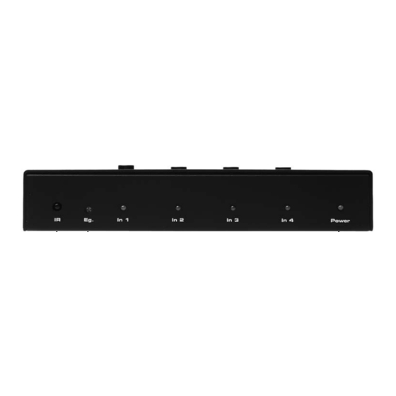
RECEIVER PANEL DESCRIPTIONS IR Relay Receiver This receiver will receive commands from the included IR remote control and from other commercial IR remote controls and relay it back to the optional IR blaster. This is intended for remote control of devices connected to the 4x4 HDMI Over CAT5 Matrix from the extended location. -
Page 13: Rmt-4Ir Remote Description
RMT-4IR REMOTE DESCRIPTION LED Indicator Input Selection Buttons Pressing on each numbered selection buttons will switch the receiver to the corresponding HDMI Input source. The LED indicator (top) will blink each time a button press is detected. Removing the battery cover will reveal these two features: Battery chamber (insert... -
Page 14: Connecting And Operating The 4X4 Hdmi Over Cat5 Matrix
CONNECTING AND OPERATING THE 4X4 HDMI OVER CAT5 MATRIX How to Connect the 4x4 HDMI Over CAT5 Matrix Connect your sources (up to four) to the 4x4 HDMI Over CAT5 Matrix using the supplied HDMI cables. If using the extension functionality of the 4x4 HDMI Over CAT5 Matrix, please connect the HDMI output ports to the HDMI extension input ports using the supplied 1 foot jumper cables. -
Page 15: 4X4 Hdmi Over Cat5 Matrix Jumper Diagram
4X4 HDMI OVER CAT5 MATRIX JUMPER DIAGRAM The 4x4 HDMI Over CAT5 Matrix uses a jumper cable system to link the matrix and extension portions together. These jumper cables are included. Please us the diagram below to setup extension functionality of the 4x4 HDMI Over CAT5 Matrix. -
Page 16: Operating The 4X4 Hdmi Over Cat5 Receiver
OPERATING THE 4X4 HDMI OVER CAT5 RECEIVER To use the 4x4 HDMI Over CAT5 Receiver, the following connections must be made: A HDMI jumper cable is connected between the HDMI output port and the HDMI extension input port. The DDC and Video CAT-5e cable must be connected between the 4x4 HDMI Over CAT5 Matrix and the 4x4 HDMI Over CAT5 Receiver. -
Page 17: Confi Guring The 4X4 Hdmi Over Cat5 Receiver
CONFIGURING THE 4X4 HDMI OVER CAT5 RECEIVER The 4x4 HDMI Over CAT5 Receiver contains a bank of 8 DIP SWITCHES. These swiches are located underneath each unit. Peeling back the black metallic sticker on the bottom of the 4x4 HDMI Over CAT5 Receiver will reveal the DIP SWITCH bank. - Page 18 CONFIGURING THE 4X4 HDMI OVER CAT5 RECEIVER Insert a small fl at head tool into the trim pot on the receiver unit. Turn the trim pot in a clockwise fashion until it comes to a stop. Do not force the trim pot beyond this point. Doing so may break the trim pot. Slowly turn the trim pot counter-clockwise in millimeter increments until the image stabilizes and all video noise disappears.
- Page 19 CONFIGURING THE 4X4 HDMI OVER CAT5 RECEIVER Pre-Emphasis Pre-Emphasis is used to help extend a signal travel over a distance of cable. When a HDMI cable connected to a display on a 4x4 HDMI Over CAT5 is over a long cable, it is recommended that Pre-Emphasis be enabled.
-
Page 20: Network Cable Wiring Diagram
Gefen has specifi cally engineered their products to work with the TIA/EIA-568-B specifi cation. Please adhere to the table below when fi eld terminating cable for use with Gefen products. Failure to do so may produce unexpected results and reduced performance. -
Page 21: Edid Management Features
EDID MANAGEMENT FEATURES EDID. What is it and what is it used for? Under normal circumstances, a source device (digital and analog) will require information about a connected device/display to assess what resolutions and features are available. The source can then cater its output to send only resolutions and features that are compatible with the attached device/ display. -
Page 22: Edid Management Modes
Same as mode 6 but will record and store the EDID in memory. This EDID will persist no matter what displays are disconnected or reconnected thereafter. EDID will remain even upon power cycle. A user submitted EDID can be uploaded in this mode using a Gefen HDMI Signal Generator. -
Page 23: Rs-232 Serial Communication
RS-232 SERIAL COMMUNICATION What features are available via the RS-232 serial communications port? The 4x4 Matrix for HDMI can accept commands through the RS-232 serial communications port located on the rear panel. The current RS-232 control features are: • Switching/routing of inputs to outputs without the RMT-16IR remote control. •... -
Page 24: Rs-232 Serial Communication Commands
RS-232 SERIAL COMMUNICATION COMMANDS Switching/Routing Binary Table ASCII Corresponding Binary ASCII Corresponding Binary RMT16-IR RMT16-IR Button Button 0011 0001 0011 1001 0011 0010 0110 0001 0011 0011 0110 0010 0011 0100 0110 0011 0011 0101 0110 0100 0011 0110 0110 0101 0011 0111 0110 0110 0011 1000... -
Page 25: Specifi Cations
SPECIFICATIONS Video Amplifi er Bandwidth ............... 165 MHz Input Video Signal ................1.2 Volts p-p Input DDC Signal ................. 5 Volts p-p (TTL) Single Link Range ..............1080p/1920 x 1200 HDMI Connector ..............Type A 19 Pin Female Link Connector ................RJ-45 Shielded Remote Control Port ............ - Page 27 Rev A3 20600 Nordhoff St., Chatsworth CA 91311 1-800-545-6900 818-772-9100 fax: 818-772-9120 www.gefen.com support@gefen.com...
Need help?
Do you have a question about the EXT-HDMI-CAT5-444 and is the answer not in the manual?
Questions and answers