Kyocera FS-1016MFP Service Manual
Hide thumbs
Also See for FS-1016MFP:
- Operation manual (92 pages) ,
- Specifications (2 pages) ,
- Features (4 pages)
Table of Contents
Advertisement
Quick Links
Advertisement
Table of Contents

Related Manuals for Kyocera FS-1016MFP


Summary of Contents for Kyocera FS-1016MFP
-
Page 1: Service Manual
FS-1016MFP SERVICE MANUAL Published in February 2006 2G470760... - Page 2 Revision history Revision Date Replaced pages Remarks...
-
Page 3: Safety Precautions
Safety precautions This booklet provides safety warnings and precautions for our service personnel to ensure the safety of their customers, their machines as well as themselves during maintenance activities. Service personnel are advised to read this booklet carefully to familiarize themselves with the warnings and precautions described here before engaging in maintenance activities. - Page 4 Safety warnings and precautions Various symbols are used to protect our service personnel and customers from physical danger and to prevent damage to their property. These symbols are described below: DANGER: High risk of serious bodily injury or death may result from insufficient attention to or incorrect compliance with warning messages using this symbol.
-
Page 5: Installation Precautions
1.Installation Precautions WARNING • Do not use a power supply with a voltage other than that specified. Avoid multiple connections to one outlet: they may cause fire or electric shock. When using an extension cable, always check that it is adequate for the rated current....................•... - Page 6 2.Precautions for Maintenance WARNING • Always remove the power plug from the wall outlet before starting machine disassembly....• Always follow the procedures for maintenance described in the service manual and other related brochures............................• Under no circumstances attempt to bypass or disable safety features including safety mechanisms and protective circuits.
- Page 7 • Do not remove the ozone filter, if any, from the copier except for routine replacement..... • Do not pull on the AC power cord or connector wires on high-voltage components when removing them; always hold the plug itself...................... •...
- Page 8 This page is intentionally left blank.
-
Page 9: Table Of Contents
CONTENTS 1-1 Specifications 1-1-1 Specifications............................1-1-1 1-1-2 Parts names............................1-1-3 (1) Operation panel..........................1-1-4 1-1-3 Machine cross section ..........................1-1-5 1-2 Installation 1-2-1 Installation environment ..........................1-2-1 1-2-2 Unpacking and installation ........................1-2-2 (1) Installation procedure ........................1-2-2 1-3 Service Mode 1-3-1 Service mode ............................1-3-1 (1) Printing the system configuration page .....................1-3-1 1-4 Troubleshooting 1-4-1 Paper misfeed detection .........................1-4-1 (1) Paper misfeed indication ........................1-4-1... - Page 10 1-6 Firmware 1-6-1 Updating the firmware on the main PWB....................1-6-1 2-1 Mechanical construction 2-1-1 Paper feeding/conveying section ......................2-1-1 (1) Paper feed section ..........................2-1-1 2-1-2 Drum section............................2-1-3 (1) Drum unit............................2-1-3 (2) Main charger unit..........................2-1-4 2-1-3 Expose section............................2-1-5 (1) Laser scanner unit..........................2-1-5 2-1-4 Developing section..........................2-1-7 (1) Developer unit ...........................2-1-7 2-1-5 Transfer section ............................2-1-9...
-
Page 11: Specifications
1-1 Specifications 1-1-1 Specifications Main body Printing system ....... Electro-photographic Originals.......... Sheets of paper, books and 3-dimensional objects Copy sizes ........Paper cassette: A4, B5 (JIS), A5, folio, legal, letter, oficio II Manual feed tray: A4, B5 (JIS), A5, folio, legal, letter, oficio II, statement, executive, A6, B6, B5 (ISO), envelope #10, envelope #9, envelope monarch, envelope #6, enve- lope C5, envelope DL, 16K Paper types........ - Page 12 Printing functions Printing speed......... A4: 16 pages per minute/Letter: 17 pages per minute First print......... 11 seconds or less × Resolution........600 600 dpi Host Interface ......... USB: 1 port (Hi-speed USB) Scanning functions Scanning Speed......Monochrome: 16 scan/min. Full color or grayscale: 4.8 scan/min. 1:1, Letter/A4, 300 dpi ×...
-
Page 13: Parts Names
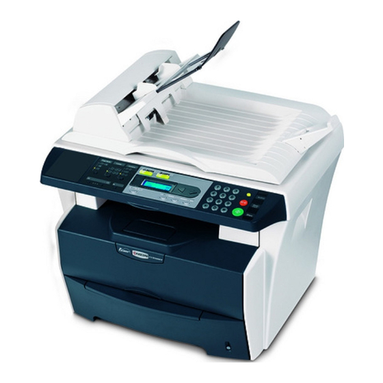
1-1-2 Parts names Figure 1-1-1 Scanner unit 14. Paper stopper Front cover 15. USB Interface connector Paper cassette 16. 5 V DC output (for print server) Manual feed tray 17. Rear cover Toner container 18. Power switch Developer unit 19. AC inlet Drum unit 20. - Page 14 (1) Operation panel Figure 1-1-2 Copy mode key and indicator 11. Exposure adjustment key/Exposure display Collate key and indicator 12. Zoom key Combine key and indicator 13. Memory overflow indicator SCAN key 14. Toner indicator COPY key and indicator 15. Scan To PC key 16.
-
Page 15: Machine Cross Section
1-1-3 Machine cross section Paper path Figure 1-1-3 Machine cross section Paper cassette Transfer section Manual feed tray 10. Fuser unit Paper feeding/conveying 11. Paper exit section section 12. Output tray Toner container 13. Operation unit Developer unit 14. Scanner unit Main charger unit 15. - Page 16 This page is intentionally left blank. 1-1-6...
-
Page 17: Installation Environment
1-2 Installation 1-2-1 Installation environment ° ° Temperature: 10 to 32.5 C/50 to 90.5 Humidity: 15 - 80%RH Power supply: 120 V AC, 9.0 A 220 - 240 V AC, 5.0 A (Average) ± ± Power source frequency: 50 Hz 0.3%/60 Hz 0.3% Installation location... -
Page 18: Unpacking And Installation
1-2-2 Unpacking and installation (1) Installation procedure Start Unpacking. Unlocking the shipping lock. Installing the toner container. Loading the paper. Installing the original table and ejection extension. Attaching the language sheet label sheets. Connecting the cables. Initializing the printer and printing a report page for test. - Page 19 Unpacking. Figure 1-2-3 Unpacking Machine (main body) Power cord Toner container Original table Ejection extension Operation guide and Installation guide CD-ROMs Language label sheets 1-2-3...
- Page 20 Unlocking the shipping lock. 1. Open the document processor (DP). 2. Unlock the shipping lock. 3. Close the document processor (DP). Document processor (DP) Shipping lock Figure 1-2-4 Installing the toner container. 1. Open the scanner unit. 2. Open the front cover. Scanner unit Front cover Figure 1-2-5...
- Page 21 3. Shake the container horizontally to distribute the toner evenly. 4. Remove the seal from the toner container. Toner container Figure 1-2-6 5. Remove the seal from the toner container. Seal Figure 1-2-7 1-2-5...
- Page 22 6. Turn the toner container release lever to the [UNLOCK] position. 7. Install the toner container in the printer. Toner container Toner container release lever Figure 1-2-8 8. Push firmly on the top of the container at the positions marked [PUSH HERE] until you hear a click.
- Page 23 Loading the paper. 1. Pull the paper cassette completely out of the machine. 2. Press the release button and adjust the paper length guide to the paper size required. 3. Adjust the position of the width guides located on the left and right sides of the paper cassette.
- Page 24 Attaching the language label sheets. 1. Remove the language label sheet. 2. Attach the language label sheet on the oper- ation panel. Language label sheet Language label sheet Operation panel Figure 1-2-12 1-2-8...
- Page 25 Connecting the cables. 1. Connect the printer cable to the USB inter- USB interface connector face connector. 2. Connect the other end of the printer cable to the PC’s USB interface connector. 3. Connect the power cord to the printer AC inlet.
- Page 26 Initializing the printer and printing a report page for test. 1. Turn the power switch on. The machine will begin to warm up after which the basic screen is displayed. 2. Press the Menu key. 3. Press the key to select [3. Report.] 4.
- Page 27 6. Click the language to be used. 7. Click Install Printer Software. The Installa- tion Wizard starts. 8. Click Next. Figure 1-2-17 9. For the simple, default installation, select Express Mode and click Next. Figure 1-2-18 NOTE: If you selected Custom Mode, select Universal Serial Bus (USB) to select the connection method, and follow the on- screen instructions.
- Page 28 Installing the scanner software. 1. Switch on the PC and activate Windows. NOTE: If the Welcome to the Found New Hardware Wizard dialog box displays, select Cancel. 2. Insert the CD-ROM (Product Library FS- 1016MFP) into the CD-ROM drive. Once the installation program launches, the License Agreement Notice is displayed.
- Page 29 The Print dialog box displays. 2. Select the drop down list of printer names. All the printers installed are listed. Select the FS-1016MFP. 3. Select the options required, enter the num- ber of copies required and if printing more than one set, select Collate. Select OK to start printing.
- Page 30 This page is intentionally left blank. 1-2 Maintenance M 1-2-14...
-
Page 31: Service Mode
1-3 Service Mode 1-3-1 Service mode (1) Printing the system configuration page Description Lists information on the settings and environments of use for this machine. Purpose To acquire the current printing environmental parameters and cumulative information. Procedure Press the Menu key. Press the key to select [3. - Page 32 This page is intentionally left blank. 1-3 Maintenance M 1-3-2...
-
Page 33: Paper Misfeed Detection
1-4 Troubleshooting 1-4-1 Paper misfeed detection (1) Paper misfeed indication When a paper misfeed occurs, the printer immediately stops printing and displays the paper misfeed message on the operation panel. To remove paper misfed in the printer, open the front cover or the rear cover or pull out the paper cas- sette.To remove original jammed in the DP, open the original cover. -
Page 34: Self-Diagnosis
1-4-2 Self-diagnosis (1) Self-diagnostic function This machine is equipped with a self-diagnostic function. When a problem is detected, the machine stops printing and an error message is displayed on the operation panel. [PRINTER ERROR] Service Call-#### Error code [SCANNER ERROR] Lamp error Error causes Figure 1-4-2Error message display... -
Page 35: Service Error Message
(2) Service error message Remarks Service error message Contents Causes Check procedures/corrective measures “####” means self- Self-diagnostic error Turn the power switch off and then back on [PRINTER ERROR] diagnostic error code. occurred. again. If this message still remains, follow Service Call-#### the self-diagnostic error code instruction. - Page 36 Remarks Service error message Contents Causes Check procedures/corrective measures Scanner motor stall for Defective scanner Replace the scanner belt spring. [SCANNER ERROR] scanner. belt spring. Motor Stall Poor contact in scan- Reinsert the connector (See page P.1-5- ner motor connector 36).
- Page 37 (3) Service call codes Remarks Code Contents Causes Check procedures/corrective measures 2000 Main motor error Defective harness Follow the flow chart. The main motor ready input is not given between engine/ for two seconds during the main motor is high voltage PWB driven.
- Page 38 Remarks Code Contents Causes Check procedures/corrective measures 4000 Polygon motor (laser scanner unit) Defective harness Follow the flow chart. error between engine/ The polygon motor ready input is not high voltage PWB given for eight seconds during the poly- and laser scanner gon motor is driven.
- Page 39 Remarks Code Contents Causes Check procedures/corrective measures 4200 PD (Pin photo diode) sensor (laser Defective main Follow the flow chart. scanner unit) error PWB. The first BD input is not given for 10 sec- Defective harness onds after power is turned on and the between main laser begins emitting.
- Page 40 Remarks Code Contents Causes Check procedures/corrective measures 4200 Continued from Continued from cont. previous page. previous page. Replace laser scanner unit. Replace main PWB. See page P.1-5-17. See page P.1-5-29. Replace main PWB. See page P.1-5-29. Turn power switch on. Turn power switch on.
- Page 41 Remarks Code Contents Causes Check procedures/corrective measures 6000 Broken heater lamp error Defective fuser Follow the flow chart. The temperature won’t rise by 1 degree thermistor. Celsius during warming up and the Broken thermal heater is turned on for 5 seconds. cutout or heater The temperature won’t rise by 1 degree lamp.
- Page 42 Remarks Code Contents Causes Check procedures/corrective measures 6010 Fuser low temperature Defective the fuser Follow the flow chart. After the fuser heater lamp is turned on, thermistor. the temperature at the upper fuser roller Defective the ° ° lower than 100 C/212 F continues for engine/high volt-...
- Page 43 Remarks Code Contents Causes Check procedures/corrective measures 6050 Broken fuser thermistor Defective the fuser Follow the flow chart. The thermistor AD value is less than 1 thermistor. for 600 ms. Defective the engine/high volt- age PWB. Start Turn power switch off, and remove power cord.
- Page 44 Remarks Code Contents Causes Check procedures/corrective measures 7980 Waste toner full (Total page count less Defective drum Follow the flow chart. than 100,000 pages of printing) unit. The toner-full sensor has detected that Defective waste the waste toner is full before the total toner full sensor.
- Page 45 Remarks Code Contents Causes Check procedures/corrective measures 7990 Waste toner full (Total page count Defective drum Follow the flow chart. more than 100,000 pages of printing) unit. The toner-full sensor has detected that Defective waste the waste toner is full before the total toner full sensor.
-
Page 46: Image Formation Problems
1-4-3 Image formation problems (1) Completely (2) All-black print- (3) Dropouts. (4) Black dots. (5) Black horizon- blank printout. out. tal streaks. See page P.1-4-15 See page P.1-4-15 See page P.1-4-16 See page P.1-4-16 See page P.1-4-16 (6) Black vertical (7) Unsharpness. -
Page 47: No Image Appears (Entirely Black)
(1) Completely blank printout Copy example Causes Check procedures/corrective measures Defective drum unit or developer unit. Open the printer top cover and check that the drum unit and developer unit is correctly seated. Check for poor contact of the main charger terminal between the main charger unit and the drum unit. -
Page 48: Dropouts
(3) Dropouts Copy example Causes Check procedures/corrective measures Defective developing roller (in the If the defects occur at regular intervals of 47.2 mm/1 ", the developer unit). problem may be the damaged developing roller (in the devel- oper unit). Replace the developer unit (See page P.1-5-6). Defective drum unit. -
Page 49: Black Vertical Streaks
(6) Black vertical streaks Copy example Causes Check procedures/corrective measures Contaminated main charger wire. Contaminated main charger wire. Clean the main charger wire by sliding the green colored cleaning knob in and out several times. Defective drum surface. Defective drum surface. A streak of toner remaining on drum after printing means that the cleaning blade (in the drum unit) is not working properly. -
Page 50: Gray Background
(8) Gray background Copy example Causes Check procedures/corrective measures Print density setting. Print density setting. The print density may be set too high. Try adjusting the print density. For details refer to the printer's operation guide. Defective drum surface potential. Defective drum surface potential. -
Page 51: Electric Problems
1-4-4 Electric problems Problem Causes Check procedures/corrective measures (1)The machine does No electricity at the power Measure the input voltage. not operate when the outlet. power switch is The power cord is not Check the contact between the power plug and the outlet. turned on. - Page 52 Problem Causes Check procedures/corrective measures (6)The feed clutch Broken feed clutch coil. Check for continuity across the coil. If none, replace the feed does not operate. clutch. Poor contact in the feed Reinsert the connector. clutch connector terminals. Defective harness between Check for continuity across the harness.
- Page 53 Problem Causes Check procedures/corrective measures (12)No transfer bias Poor contact of transfer (See page P.1-5-14). is output. bias terminal and transfer bias terminal (J1, J2, J3) on the engine/high voltage PWB. Defective engine/high volt- age PWB. (13)The message Defective paper sensor on Replace the engine/high voltage PWB (See page P.1-5-14).
-
Page 54: Mechanical Problems
1-4-5 Mechanical problems Problem Causes/check procedures Corrective measures Check if the surfaces of the feed roller is dirty Clean with isopropyl alcohol. No primary paper feed. with paper powder. Check if the paper feed roller is deformed. Check visually and replace any deformed paper feed roller. -
Page 55: Assembly And Disassembly
1-5 Assembly and Disassembly 1-5-1 Precautions for assembly and disassembly (1) Precautions Be sure to turn the power switch off and disconnect the power plug before starting disassembly. When handling PWBs, do not touch connectors with bare hands or damage the board. Do not touch any PWB containing ICs with bare hands or any object prone to static charge. -
Page 56: Outer Covers And Scanner Unit
1-5-2 Outer covers and scanner unit (1) Detaching and refitting the right cover, left cover and top cover <Procedure> 1. Remove the paper cassette. 2. Open the scanner unit. 3. Open the front cover. 4. Unlatch the four latches and then remove the right cover. - Page 57 6. Remove the scanner unit (See page P.1-5- hook 22). 7. While opening the rear cover and then Top cover hook remove the two screws. 8. While unhooking the two hooks and then Top cover remove the top cover. Top cover Screw Screw Rear cover...
-
Page 58: Paper Feeding/Conveying Section
1-5-3 Paper feeding/conveying section (1) Detaching and refitting the paper feed roller <Procedure> 1. Remove the paper cassette. 2. Remove the paper feed roller. 3. Check or replace the paper feed roller and refit all the removed parts. Paper feed roller Figure 1-5-4Removing the paper feed roller 1-5-4... -
Page 59: Detaching And Refitting The Transfer Roller
(2) Detaching and refitting the transfer roller <Procedure> 1. Remove the developer unit and drum unit (See page P.1-5-6). Paper passing direction 2. Remove the transfer roller from bushes. 3. Check or replace the transfer roller and refit Short Long all the removed parts. -
Page 60: Process Section
1-5-4 Process section (1) Detaching and refitting the developer unit and drum unit <Procedure> 1. Open the scanner unit. Front cover 2. Open the front cover. 3. Remove the developer unit (with toner con- tainer. Developer unit Figure 1-5-6Removing the developer unit 4. -
Page 61: Detaching And Refitting The Main Charger Unit
(2) Detaching and refitting the main charger unit <Procedure> 1. Remove the drum unit (See page P.1-5-6). 2. While pushing on the main charger terminal (1), slide the main charger unit (2). 3. Remove the main charger unit (3) by lifting 4. -
Page 62: Fuser Unit
1-5-5 Fuser unit (1) Detaching and refitting the fuser unit <Procedure> 1. Remove the outer covers (See page P.1-5- 2. Remove the two connectors. 3. Remove the wire from two clamps. Clamp Connector Wire Clamp Connector Figure 1-5-9 4. Pull out the rear cover axises (with springs) from the axis holes. - Page 63 5. Remove the two screws and then remove the fuser unit. Screw Screw Fuser unit Figure 1-5-11 6. Remove the two screws and then separate the upper fuser frame and lower fuser frame. 7. Check or replace the fuser unit and refit all the removed parts.
-
Page 64: Detaching And Refitting The Heater Lamp, Heat Roller, Fuser Thermistor, Thermal Cutout, And Press Roller
(2) Detaching and refitting the heater lamp, heat roller, fuser thermistor, thermal cutout, and press roller <Procedure> 1. Remove the fuser unit (See page P.1-5-8). Screw 2. Remove the two screws and terminal. 3. Remove the heater lamp. Fuser gear * Seat the heater lamp aligning its wattage mark and welding mark faced with the cor- rect direction and side. - Page 65 4. Pull the heat R bush and heat L bush (with Gear heat roller) from the upper fuser guide. 5. Remove the heat R bush, heat L bush and Bush heat gear from the heat roller. Heat roller Heat roller Heat roller Bush Bush...
- Page 66 7. Remove the two screws (nuts), plate cord, and terminal. 8. Remove the thermal cutout. Cord plate Screw Thermal cutout Screw Terminal Figure 1-5-16 1-5-12...
- Page 67 9. Remove the press roller from the bushes. 10. Check or replace the heater lamp, heat roller, fuser thermistor, thermal cutout, or Press roller press roller and refit all the removed parts. Bush Bush Lower fuser frame Figure 1-5-17Removing the press roller 1-5-13...
-
Page 68: Detaching And Refitting The Engine/High Voltage Pwb And Power Source Pwb
(3) Detaching and refitting the engine/high voltage PWB and power source PWB <Procedure> 1. Remove the developer unit and drum unit (See page P.1-5-6). 2. Remove the paper cassette. 3. Remove the scanner unit (See page P.1-5- 22). 4. Remove the six connectors. * When seating the engine/high voltage PWB, ensure that the developer bias termi- nal spring is correctly in contact with the... - Page 69 5. Turn the printer bottom side up. Screws 6. Remove the five screws and then remove the bottom frame plate with PWBs (behind the plate). Screws Bottom frame plate (Transfer bias terminal) Figure 1-5-19 1-5-15...
- Page 70 7. Remove the one screw and terminal from the bottom frame plate. EEPROM * When securing the grounding terminal, Screw hook the grounding wire to the projection. Socket 8. Remove the two connectors from power Screw source PWB. 9. Remove the three screws from power source PWB and power source fan motor.
-
Page 71: Detaching And Refitting The Laser Scanner Unit
(4) Detaching and refitting the laser scanner unit <Procedure> 1. Remove the outer covers (See page P.1-5- Screw 2. Remove the two screws and then remove the LSU lid. LSU lid Screw Figure 1-5-21 1-5-17... - Page 72 3. Remove the three screws. Connector 4. Remove the two connectors and then Screw remove the laser scanner unit. 5. Check or replace the laser scanner unit and Laser scanner unit refit all the removed parts. Screw Screw Figure 1-5-22 1-5-18...
-
Page 73: Detaching And Refitting The Eraser Lamp (Pwb)
(5) Detaching and refitting the eraser lamp (PWB) <Procedure> 1. Remove the laser scanner unit (See page P.1-5-17). 2. Remove the one connector. 3. Remove the wire from two clamps. Clumps Wire Connector Figure 1-5-23 4. Remove the wire form clamp. Wire 5. -
Page 74: Detaching And Refitting The Drive Unit
(6) Detaching and refitting the drive unit <Procedure> 1. Remove the right cover (See page P.1-5-2). Connectors 2. Remove the three connectors. 3. Remove the two screws and then remove the two grounding plates. 4. Remove the two stoppers and then remove the two clutches. -
Page 75: Detaching And Refitting The Main Motor
(7) Detaching and refitting the main motor <Procedure> 1. Remove the right cover (See page P.1-5- 24). 2. Remove the one connector from main motor. 3. Remove the four screws and then remove the main motor. 4. Check or replace the main motor and refit all the removed parts. -
Page 76: Scanner Unit
1-5-6 Scanner unit (1) Detaching and refitting the scanner unit <Procedure> 1. Remove the right cover and left cover (See page P.1-5-2). 2. Open the scanner unit. Scanner unit 3. While pressing the locks and then remove (DP) the lift link L and lift link R. Lift link L Lift link R Locks... - Page 77 4. Remove the two screws and then remove the two terminals. 5. Remove the three connectors. 6. Remove the two pivot pins. Pivot pin 7. Remove the scanner unit (with DP). 8. Check or replace the scanner unit and refit all the removed parts.
-
Page 78: Detaching And Refitting The Optical Module Unit
(2) Detaching and refitting the optical module unit <Procedure> Original table 1. Remove the scanner unit (See page P.1-5- 22). 2. Unlatch the two latches and then remove the original table. Ejection extension 3. Remove the ejection extension. Latches Figure 1-5-30 Screw 4. - Page 79 9. Remove the two screws and then remove Document processor (DP) the DP signal cable. Screws 10. While pressing the hinge locks and then remove the hinges of DP. DP signal cable Hinge lock Hinge Figure 1-5-32 1-5-25...
- Page 80 11. Remove the three screws. Screw Screw Operation unit Screw Figure 1-5-33 12. Remove the FFC form FFC connector. 13. Remove the operation unit. Operation unit FFC connector Operation unit Figure 1-5-34 1-5-26...
- Page 81 14. Remove the four screws and then remove Screw the scanner upper housing. Scanner upper Screw housing Screw Screw Screw Figure 1-5-35 15. Remove the sliding rod. Scanner bottom housing Sliding rod Optical module unit Sliding rod Figure 1-5-36 1-5-27...
- Page 82 16. Remove the two FFCs. FFC connector 17. Remove the optical module unit from the FFC connector Optical module unit scanner belt. 18. Check or replace the optical module unit and refit all the removed parts. Scanner belt Bottom view Scanner belt Optical module unit...
-
Page 83: Detaching And Refitting The Main Pwb
(3) Detaching and refitting the main PWB <Procedure> 1. Remove the scanner unit (See page P.1-5- Screw 22). Screw 2. Remove the original table and ejection Screw extension (See page P.1-5-24). Screw 3. Remove the six screws. Main PWB cover 4. - Page 84 6. Remove the six screws and three terminals. Screw Screw 7. Remove the main PWB. 8. Check or replace the main PWB and refit all Screw the removed parts. Screw Screw Screw Main PWB Terminals Scanner unit Silicon rubber (Q9) Silicon rubber (U14) Silicon...
-
Page 85: Detaching And Refitting The Exposure Lamp
(4) Detaching and refitting the exposure lamp <Procedure> 1. Remove the optical module unit (See page Hook P.1-5-24). 2. Remove the CCD cover. CCD cover Optical module unit Stopper Figure 1-5-40 3. Remove the one connector. Hook 4. Remove the adhesive tape. 5. - Page 86 6. Remove the wires from the exposure lamp Wire holder. 7. Remove the exposure lamp. 8. Check or replace the exposure lamp and refit all the removed parts. Exposure lamp Wire Exposure lamp holder Figure 1-5-42 1-5-32...
-
Page 87: Detaching And Refitting The Inverter Pwb
(5) Detaching and refitting the inverter PWB <Procedure> 1. Remove the optical module unit (See page P.1-5-24). 2. Cut the band. Optical module unit Band Figure 1-5-43 3. Remove the CCD cover. Hook CCD cover Optical module unit Stopper Figure 1-5-44 1-5-33... - Page 88 4. Remove the two connectors. Connector 5. Remove the one screw and then remove the inverter PWB. 6. Check or replace the inverter PWB and refit Screw all the removed parts. Inverter PWB Connector Figure 1-5-45 1-5-34...
-
Page 89: Detaching And Refitting The Scanner Home Position Sensor
(6) Detaching and refitting the scanner home position sensor <Procedure> 1. Remove the optical module unit (See page P.1-5-24). Hook 2. Remove the CCD cover. CCD cover Optical module unit Stopper Figure 1-5-46 3. Remove the one connector. 4. Remove the one screw and then remove the Screw scanner home position sensor. -
Page 90: Detaching And Refitting The Scanner Motor
(7) Detaching and refitting the scanner motor <Procedure> 1. Remove the optical module unit (See page Hook P.1-5-24). 2. Remove the one connector. 3. Remove the scanner motor wire. Connector CCD cover Scanner motor wire Stopper Optical module unit Figure 1-5-48 4. -
Page 91: Document Processor (Dp)
1-5-7 Document processor (DP) (1) Detaching and refitting the document processor (DP) <Procedure> Screw 1. Remove the scanner unit (See page P.1-5- 22). Screw Screw 2. Remove the original table (See page P.1-5- 24). 3. Remove the six screws and then remove the Screw Main PWB cover Screw... -
Page 92: Detaching And Refitting The Pad Assembly
(2) Detaching and refitting the pad assembly <Procedure> 1. Open the DP cover. Pad assembly 2. Press both arms of the pad assembly inwardly with your fingers and then pull out the pad assembly. 3. Check or replace the pad assembly and refit all the removed parts. -
Page 93: Detaching And Refitting The Original Feed Roller
(3) Detaching and refitting the original feed roller <Procedure> 1. Open the DP front cover. 2. Open the shaft holder. 3. Remove the original feed roller. 4. Check or replace the original feed roller and refit all the removed parts. Shaft holder DP front cover... - Page 94 This page is intentionally left blank. 1-5-40...
-
Page 95: Updating The Firmware On The Main Pwb
1-6 Firmware 1-6-1 Updating the firmware on the main PWB Procedure Note: Ensure the machine is plugged in and connected to the PC’s USB port, install the updating firmware folder (files) before firm- ware updating. 1. Double-click [FWUpdate.exe] in the [Auto Updating firmware program folder Update] updating firmware program folder. - Page 96 This page is intentionally left blank. 1-6-2...
-
Page 97: Paper Feeding/Conveying Section
2-1 Mechanical construction 2-1-1 Paper feeding/conveying section The paper feeding/conveying system picks up paper from the paper cassette, manual feed tray, feeds it in the printer and delivers in the output tray. Paper is feed at the precise timing in synchronization with data processing. (1) Paper feed section The figure below shows the components in the paper feeding/conveying section and the paths through which the paper travels. - Page 98 Engine/high voltage PWB Connect PWB +24V3 YC403-1 YC3-13 YC401-8 Feed clutch FEDSOLON FEDDOLON YC403-2 YC3-8 YC401-3 REGSOLON YC3-7 YC401-2 +24V3 Registration YC402-1 +24V3 REGDR YC3-6 YC401-1 clutch YC402-2 Registration sensor +24V3 CN1-1 YC5-1 Paper sensor CN1-2 YC5-2 MMOTRDY YC5-3 CN1-3 MOTCLK YC5-4 CN1-4...
-
Page 99: Drum Section
2-1-2 Drum section (1) Drum unit The durable layer of organic photoconductor (OPC) is coated over the aluminum cylinder base. The OPC tend to reduce its own electrical conductance when exposed to light. After a cyclic process of charging, exposure, and development, the electrostatic image is constituted over the OPC layer. -
Page 100: Main Charger Unit
(2) Main charger unit As the drum rotates in a “clean (neutral)” state, its photoconductive layer is given a uniform, positive (+) corona charge dis- persed by the main charger wire. Due to high-voltage scorotron charging, the charging wire can get contaminated by oxi- dization after a long run. -
Page 101: Expose Section
2-1-3 Expose section (1) Laser scanner unit The charged surface of the drum is then scanned by the laser beam from the laser scanner unit. The laser beam (780 nm wavelength) beam is dispersed as the polygon motor revolves (27959 rpm) to reflect the laser beam over the drum. - Page 102 Figure 2-1-7Laser scanner unit Laser diode ..........Emits diffused, visible laser. Cylindrical lens..........Compensates the vertical angle at which the laser beam hits a polygon mirror segment. Polygon mirror (motor) ........ Has six mirror segments around its hexagonal circumference; each mir- ror corresponding to one scanned line width on the drum when laser beam scans on it.
-
Page 103: Developing Section
2-1-4 Developing section (1) Developer unit The latent image constituted on the drum is developed into a visible image. The developing roller contains a 3-pole (S-N- S) magnet core and an aluminum cylinder rotating around the magnet core. Toner attracts to the developing roller since it is powdery ink made of black resin bound to iron particles. - Page 104 Engine/high voltage PWB Developing bias output 350 + 5 V DC + AC Developing roller Figure 2-1-9Developing section block diagram 2-1-8...
-
Page 105: Transfer Section
2-1-5 Transfer section The image developed by toner on the drum is transferred onto the paper because of the electrical attraction between the toner itself and the transfer roller. The transfer roller is negatively biased so that the positively charged toner is attracted onto the paper while it is pinched by the drum and the transfer roller. -
Page 106: Cleaning Section
2-1-6 Cleaning section After the transferring process, the drum needs to be physically cleaned of toner which is residual after the development process. The cleaning blade is constantly pressed against the drum and scrapes the residual toner off to the sweep roller. The waste toner is collected at the output end of the sweep roller and sent back to the toner container, into the waste toner reservoir. -
Page 107: Fuser Section
2-1-7 Fuser section (1) Fuser unit The toner on the paper is molten and pressed into the paper as it passes between the heat roller and the press roller in the fuser unit. The heat roller has a heater lamp (750 W) inside which continuously turns on and off by the fuser thermistor to maintain the constant temperature onto the heat roller surface. - Page 108 Fuser unit Power source PWB Engine/high voltage PWB Thermal cutout HEATN YC2-6 YC1-6 CN1-1 SLEEP YC2-7 YC1-7 ZCROSS CN1-3 YC2-9 YC1-9 Fuser heater lamp Fuser thermistor YC7-2 THERM YC7-1 Figure 2-1-15Fuser section block diagram 2-1-12...
-
Page 109: Paper Exit Section
2-1-8 Paper exit section (1) Paper exit section The paper exit section transports the paper which passed the fuser unit towards the output tray. The paper which passed through the fuser unit turns on the exit sensor which is driven by the fuser actuator in the fuser unit, and is led by the guide comprised of the rear cover and the frame, finally reaching the FD roller. - Page 110 Fuser unit Engine/high voltage PWB EXITN YC2-8 YC1-8 Exit sensor Power source PWB Figure 2-1-17Paper exit section block diagram 2-1-14...
-
Page 111: Scanner Section
2-1-9 Scanner section (1) Scanner unit Figure 2-1-18Scanner section Scanner upper housing Exposure lamp Scanner bottom housing Mirror Contact glass (10) Mirror Size indicator (11) Mirror Optical module unit housing (12) Lens Lamp housing (13) CCD PWB CCD cover Original Platen Optical module unit Main PWB... -
Page 112: Optical Module Unit
(2) Optical module unit The optical module unit consists of an exposure lamp, three mirrors, a lens, a CCD PWB, and so on. Also an inverter PWB for driving the exposure lamp and a scanner home position sensor for detecting the home position of the optical module unit are incorporated. -
Page 113: Document Processor (Dp) Section
2-1-10 Document processor (DP) section (1) Document processor (DP) Figure 2-1-21Document processor (DP) section Original feed roller DP bottom housing Pad assembly DP frame Original conveying roller DP contact plate Original conveying pulley (10) Original exit roller DP upper housing (11) Original exit pulley DP cover (12) Original table... - Page 114 This page is intentionally left blank. 2-1-18...
-
Page 115: Electrical Parts Layout
2-2 Electrical Parts Layout 2-2-1 Electrical parts layout (1) Electrical parts layout Fuser unit Drum unit Laser scanner unit Developer unit Figure 2-2-1 MFP main frame Engine/high voltage PWB ......Controls the input/output of electrical parts and generates the high volt- age. - Page 116 Optical module unit Scanner unit Figure 2-2-2 Scanner unit and document processor (DP) Main PWB ............ Controls the software such as the print data processing and provides the interface with computer. Operation panel PWB ........Indicates the LED indicators and controls key inputs. Motor driver PWB.........
-
Page 117: Power Source Pwb
2-3 Operation of the PWBs 2-3-1 Power source PWB Power source PWB Power Rectification switch input smoothing circuit Noise D10-13 filter NTC1 24V1 circuit 24 V DC (L1) rectification/ smoothing output circuit Switching Overvoltage 5 V DC control detection rectification/ Heater circuit circuit... - Page 118 Figure 2-3-2Power source PCB silk-screen diagram Connector Pin No. Signal Voltage Description 220 - 240 V AC AC power input Connected 120 V AC to the AC 220 - 240 V AC AC power input inlet 120 V AC 220 - 240 V AC Power supply for heater lamp (On/Off) Connected 120 V AC...
-
Page 119: Engine/High Voltage Pwb
2-3-2 Engine/high voltage PWB Engine/high voltage PWB Connect EECLK EEPROM EEDIO (U2) BUZZ RESETN Reset IC (U3) Buzzer REGSOLON Registration clutch FANH Cooling FEDSOLON Feed clutch FANL fan motor MMOTON Toner empty TONER MOTCLK Main motor sensor MMOTRDY Registration (U1) sensor TNFULL Waste toner... - Page 120 YC10 YC11 Figure 2-3-4Engine/high voltage PWB silk-screen diagram 2-3-4...
- Page 121 Connector Pin No. Signal Voltage Description 5 V DC 5 V DC power input Connected 5 V DC 5 V DC power input to the power Ground source PWB Ground +24V 24 V DC 24 V DC power output (via interlock switch) HEATN 0/24 V DC Heater lamp: On/Off...
- Page 122 Connector Pin No. Signal Voltage Description ERASPW 24 V DC 24 V DC power output Connected ERASER 0/24 V DC Eraser lamp (PWB): On/Off to the eraser lamp (PWB) +24V1 24 V DC 24 V DC power output Connected 0/12/24 V DC Cooling fan motor: Full speed/Half speed/Off to the cool- ing fan...
-
Page 123: Main Pwb
2-3-3 Main PWB Main PWB CCD PWB SDRAM NVRAM 32 MB 2 kbytes image sensor VD [0:7] Real time Stepping Scanner clock motor CCD control motor driver IC Video I/F ASIC Motor control (CPU) Logic IC Motor driver PWB Serial communication I/F Original Stepping... - Page 124 Figure 2-3-6Main PWB silk-screen diagram 2-3-8...
-
Page 125: Wiring Diagram
2-4 Appendixes (1) Wiring diagram 2-4-1... -
Page 126: Repetitive Defects Gauge
(2) Repetitive defects gauge First occurrence of defect 24 mm ( ") [Upper registration roller] 15/16 38 mm (1 ") [Lower registration roller] 47.2 mm (1 ") [Developing roller] 48 mm (1 ") [Transfer roller] 63 mm (2 ") [Heat roller or press roller] 94 mm (3 ") [Drum] 11/16...
Need help?
Do you have a question about the FS-1016MFP and is the answer not in the manual?
Questions and answers