Kärcher HD 2.8/20 Pb Operator's Manual
Hide thumbs
Also See for HD 2.8/20 Pb:
- Operator's manual (15 pages) ,
- Operator's manual (12 pages) ,
- Operator's manual (15 pages)
Table of Contents
Advertisement
OPERATOR'S MAN U AL
HD 2.8/20 Pb / BG-282037
HD 2.5/27 Pb / BG-252737
HD 3.0/30 Pb / BG-303037
HD 3.7/35 Pb / BG-373537
HD 3.0/40 Pb / BG-304037
To locate your local Kärcher Shark Commercial Pressure Washer Dealer nearest you,
visit www.karchercommercial.com or www.karchershark.com
MODEL
ORDER #
1.575-150.0
1.575-151.0
1.575-152.0
1.575-154.0
1.575-155.0
R
9.800-083.0
Advertisement
Table of Contents

Related Manuals for Kärcher HD 2.8/20 Pb


Summary of Contents for Kärcher HD 2.8/20 Pb
- Page 1 OPERATOR’S MAN U AL MODEL ORDER # HD 2.8/20 Pb / BG-282037 1.575-150.0 HD 2.5/27 Pb / BG-252737 1.575-151.0 HD 3.0/30 Pb / BG-303037 1.575-152.0 HD 3.7/35 Pb / BG-373537 1.575-154.0 HD 3.0/40 Pb / BG-304037 1.575-155.0 To locate your local Kärcher Shark Commercial Pressure Washer Dealer nearest you, visit www.karchercommercial.com or www.karchershark.com...
-
Page 3: Table Of Contents
CONTENTS Introduction & Important Safety Information .........4-5 Component Identifi cation ................. 6 Assembly Instructions ................7 Operating Instructions................8-9 Detergents & Cleaning Techniques ............10 Shut Down and Clean-Up ..............11 Storage ....................11 Troubleshooting ..................12 Adjusting Unloader Valves ..............12 Preventative Maintenance .............. -
Page 4: Introduction & Important Safety Information
INTRODUCTION & IMPORTANT SAFETY INFORMATION Thank you for purchasing this Pressure Washer. WARNING: Risk of asphyxiation. WARNING Use this product only in a well We reserve the right to make changes at any time ventilated area. without incurring any obligation. 5. -
Page 5: Important Safety Information
IMPORTANT SAFETY INFORMATION WARNING: Keep wand, hose, and WARNING: High pressure devel- WARNING WARNING water spray away from electric oped by these machines will wiring or fatal electric shock may cause personal injury or equip- result. ment damage. Keep clear of nozzle. -
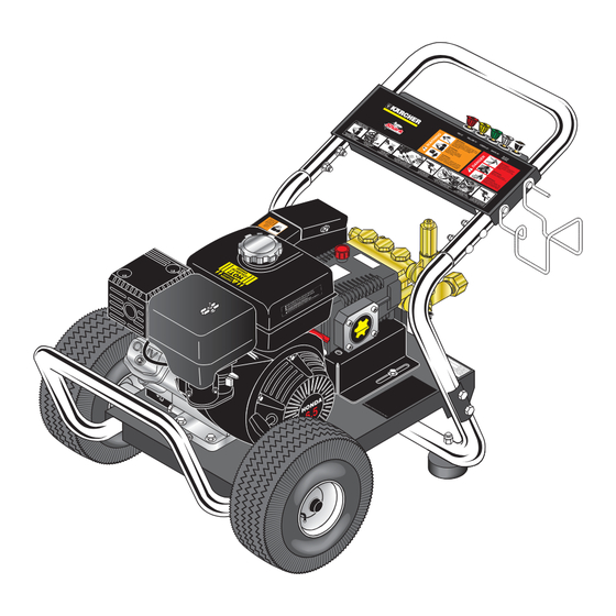
Page 6: Component Identifi Cation
COMPONENT IDENTIFICATION Unloader Pump Protector Pump Straight Through Wand Detergent Injector Spray Gun Inlet Trigger Screen Pressure Nozzle Garden Hose (not included) Starter Grip High Pressure Hose Detergent Bucket (not included) Pump — Develops high pressure. Wand — Must be connected to the spray gun. Starter Grip—... -
Page 7: Assembly Instructions
ASSEMBLY INSTRUCTIONS Carriage Bolts Hose/Spray Gun Handle Bolt Storage Bracket Alignment Holes Washer Frame Assy. Studs STEP 1: Attach the handle to the STEP 2: Insert the carriage bolt STEP 3: Attach the spray gun/hose frame of the pressure washer. Note: through the holes from the outside storage handle, and bracket to It may be necessary to move the... -
Page 8: Operating Instructions
OPERATING INSTRUCTIONS Pump Oil Dipstick Engine Oil Dipstick Oil Window STEP 1: Check engine oil level. Oil level should be level with the bottom STEP 2: Remove shipping cap and of the oil fi ller neck. Be sure the machine is level when checking the oil install oil dipstick. - Page 9 OPERATING INSTRUCTIONS (CONT.) On-Off Switch STEP 7: Turn the engine switch to "On" position. STEP 8: Pull the starter grip. If the engine fails to start after 2 pulls, squeeze the trigger gun to release pressure On Briggs engines, move the throttle lever to "Fast" and repeat step.
-
Page 10: Detergents & Cleaning Techniques
DETERGENTS & GENERAL CLEANING TECHNIQUES THERMAL PUMP PROTECTION WARNING: Some detergents WARNING may be harmful if inhaled or If you run the engine on your pressure washer for 1-2 ingested, causing severe nau- minutes without pressing the trigger on the spray gun, sea, fainting or poisoning. -
Page 11: Shut Down And Clean-Up
SHUTTING DOWN AND CLEAN-UP On-Off Switch STEP 1: Remove detergent suc- STEP 2: Turn off the engine. STEP 3: Turn off wa- tion tube from container and insert ter supply. into one gallon of fresh water. Slide nozzle forward for low pressure or to connect black detergent nozzle into wand quick coupler. -
Page 12: Troubleshooting
TROUBLESHOOTING PROBLEM POSSIBLE CAUSE SOLUTION LOW OPERATING Faulty pressure gauge Install new gauge. PRESSURE Use larger supply hose; clean fi lter at Insuffi cient water supply water inlet. Match nozzle number to machine and/or Old, worn or incorrect spray nozzle replace with new nozzle. -
Page 13: Preventative Maintenance
PREVENTATIVE MAINTENANCE This pressure washer was produced with the best available materials and quality craftsmanship. However, you as the owner have certain responsibilities for the correct care of the equipment. Attention to regular preventative maintenance procedures will assist in preserving the performance of your equipment. Contact your dealer for maintenance. -
Page 14: Models 1.575-150.0, 1.575-151.0 Exploded View
EXPLODED VIEW - 1.575-150.0, 1.575-151.0 “Th lifo a to A Sp e ha s Th . Op d bir n Sta y be n of n to e Pre e Ag rt Fir s for n Re e Op d Dry s or .”... -
Page 15: Models 1.575-150.0, 1.575-151.0 Exploded View Parts List
EXPLODED VIEW PARTS LIST - 1.575-150.0, 1.575-151.0 ITEM PART NO. DESCRIPTION 9.802-064.0 Grommet, Rubber, Nozzle Holder 9.803-122.0 Handle, Grab, Chrome 9.800-723.0 Label, Cold Water Handle 9.803-126.0 Plate, Warning/Instructions, Black 9.803-098.0 Hanger, Hose/Wand 9.802-706.0 Bolt, Carriage, 1/4"-20 x 1-3/4", Zinc 9.800-110.0 Label, Belt Guard 9.802-741.0 Bolt, 8mm x 16mm Hex... -
Page 16: Exploded View Parts List
EXPLODED VIEW PARTS LIST - 1.575-150.0, 1.575-151.0 ITEM PART NO. DESCRIPTION Unloader, See Specifi cations Pages 22-23 9.802-171.0 Nipple, 3/8" x 3/8" NPT ST Male 9.802-146.0 Swivel, 1/2" MP x 3/4" GHF w/Strainer 9.802-163.0 Strainer, 1/2" PA, Inline Plastic 9.800-008.0 Label, Danger Cool Engine Engine, See Specifi... -
Page 17: Models 1.575-152.0, 1.575-154.0,155 Exploded View
EXPLODED VIEW - 1.575-152.0,154.0,155.0 Pump 155.0 Pump 152.0 “Th ifor t con tain A Spa s che t Can atin g to tion Fire Fire y be rt Fire uire s Equ s Aro s or tion uire s or tion .”... -
Page 18: Models 1.575-152.0, 1.575-154,155 Exploded View Parts List
EXPLODED VIEW PARTS LIST - 1.575-152.0,154.0,155.0 ITEM PART NO. DESCRIPTION 9.802-064.0 Grommet, Rubber, Nozzle Holder 9.803-122.0 Handle, Grab, Chrome 9.800-723.0 Label, Cold Water Handle 9.803-126.0 Plate, Warning/Instruction, Black 9.803-098.0 Hanger, Hose/Wand 9.802-706.0 Bolt, Carriage, 1/4"-20 x 1-3/4", Zinc 9.800-046.0 Label, Belt Guard (152.0, 154.0,155.0) 9.802-753.0 Bolt, 1/4"... - Page 19 EXPLODED VIEW PARTS LIST - 1.575-152.0,154.0,155.0 IITEM PART NO. DESCRIPTION 9.802-190.0 Valve, E-Z Start, 3/8" MPT x 1/8" FPT 9.804-065.0 Valve, E-Z Start, 1/4" MPT x 1/8" FPT (152.0) 8.706-207.0 Elbow, 3/8", Street 8.706-200.0 Elbow, 1/4", Street (152.0) 9.804-025.0 Pump Protector, 1/4" PTP (All except 155.0) Pump, See Specifi...
- Page 20 EXPLODED VIEW PARTS LIST - 1.575-152.0,154.0,155.0 ITEM PART NO. DESCRIPTION 8.718-980.0 Washer, 5/16" Flat (152.0) 9.802-807.0 Washer, 3/8" Flat (155.0) 9.802-367.0 Unloader, AL-VRT 607 w/Easy Start (155.0) 9.802-870.0 Block, Unloader, 3/8" x 3/8" 1.25 Stee (155.0) 9.802-728.0 Bolt, 3/8" x 2", NC HH (155.0) 9.802-807.0 Washer, 3/8"...
-
Page 21: Hose And Spray Gun Assembly
HOSE & SPRAY GUN ASSEMBLY HOSE & SPRAY GUN ASSEMBLY PARTS LIST ITEM PART NO. DESCRIPTION 9.802-219.0 Wand Assy., Side Grip w/1/4" Coupler, 35-1/2" 8.711-348.0 Spray Gun, AP 1000 9.802-164.0 Coupler, 1/4” Female, Brass Nozzle, See Breakdown for Part Numbers 8.739-125.0 Hose, 3/8"... -
Page 22: Specifi Cations
SPECIFICATIONS Pressure Nozzle Pump Unloader Engine Engine Pump Pump Pulley Model (PSI) Size Pump Part No. Part No. Part No. Pulley Part No. 1.575-150.0 2000 KD3030 8.715-214.0 9.175-018.0 GX160 (5.5hp) 9.802-316.0 AK74H 9.802-369.0 1.575-151.0 2700 KD3030 8.715-214.0 9.175-018.0 GX200 (6.5hp) 9.802-317.0 BK80H 9.802-380.0... - Page 23 SPECIFICATIONS Pump Bushing Engine Pulley Engine Bushing Belt Belt Model Bushing Part No. Pulley Part No. Bushing Part No. Size Part No. 1.575-150.0 24MM 9.802-402.0 AK39H 9.803-898.0 HX3/4" 9.803-897.0 AX33 (1) 9.803-896.0 1.575-151.0 24MM 9.802-402.0 BK36H 9.802-379.0 HX3/4" 9.803-897.0 BX32 (1) 9.802-413.0 1.575-152.0 24MM...
-
Page 24: Ar-Al Unloader Exploded View & Parts List
AR-AL UNLOADER EXPLODED VIEW AND PARTS LIST AR - AL 607 #9.802-367.0 7-8 Gpm, 4200 Psi 9.800-083.0 • Rev. 04/10A... - Page 25 AR-AL UNLOADER EXPLODED VIEW AND PARTS LIST ITEM PART NO. DESCRIPTION ITEM PART NO. DESCRIPTION 8.718-371.0 Check Connector 83-005106301 Spring Pin 9.804-536.0 ‡ O-Ring 2068 83-005000101 Back Ring 9.804-646.0 Shutter Spring 9.804-590.0 ‡ O-Ring 2050 9.804-538.0 Shutter 83-005020003 Body By Pass 1/4 G-F 9.804-539.0 ‡...
-
Page 26: Uu1 Unloader Exploded View & Parts List
UU1 UNLOADER EXPLODED VIEW 9.175-018.0 UU1 3500PSI, UNIVERSAL UNLOADER (SPARE) UU1 UNLOADER EXPLODED VIEW PARTS LIST ITEM PART # DESCRIPTION KIT QTY ITEM PART # DESCRIPTION KIT QTY 8.749-792.0 Piston housing 9.149-006.0 Sliding connector guide Piston O-ring backup 6X 1.45X 1.68 Piston O-ring back up Conical seal 8.749-796.0 Main block... -
Page 27: Km.2 Pump Exploded View And Parts List
KM.2 PUMP EXPLODED VIEW 8.904-689.0 KM3540R.2 9.803-405.0 KM4030R.2 9.803-406.0 KM4030L.2 9.802-343.0 KM4035R.2 9.803-407.0 KM4035L.2 9.802-342.0 KM5030R.2 9.803-408.0 KM5030L.2 TORQUE SPECS Item # Ft.-lbs KM.2 PUMP EXPLODED VIEW PARTS LIST ITEM PART NO. DESCRIPTION ITEM PART NO. DESCRIPTION 26 9.802-944.0 Hexagonal Screw 8.717-130.0 Crankcase 9.803-196.0 Plunger Guide 27 8.717-210.0 Closed Bearing... - Page 28 KM.2 PUMP EXPLODED VIEW PARTS LIST (CONT.) ITEM PART NO. DESCRIPTION 42 9.803-144.0 Plunger Rod 43 9.803-158.0 Connecting Rod 44 9.802-913.0 Snap Ring 45 9.802-916.0 Connecting Rod Pin 46 9.803-218.0 Spring Washer 47 9.803-238.0 Connecting Rod Screw 48 8.933-016.0 O-Ring, Ø2.62 x 126.67 49 9.803-165.0 Crankcase Cover 50 9.803-197.0...
-
Page 29: Kd.1 Pump Exploded View And Parts List
KD.1 SERIES PUMP EXPLODED VIEW 9.803-417.0 KD 3025.1 9.804-006.0 KD 3030.1 9.804-019.0 KD 4020.1 TORQUE SPECS Item # Ft.-lbs KD.1 SERIES PUMP EXPLODED VIEW PARTS LIST ITEM PART NO. DESCRIPTION ITEM PART NO. DESCRIPTION 9.803-938.0 Crankcase 11* 9.803-947.0 O-Ring Ø1.78 x 15.54 See Kits Below Plunger Oil Seal 12* See Kits Below Valve Assembly See Kits Below O-Ring Ø1.78 x 28.30... - Page 30 KD.1 SERIES PUMP EXPLODED VIEW PARTS LIST ITEM PART NO. DESCRIPTION 8.933-010.0 Crankshaft Seal 34* See Kits Below Plunger Nut 35* See Kit Below Copper Spacer 36* See Kits Below Plunger, 15mm (3030) See Kits Below Plunger, 18mm (4020, 3025) 37* See Kits Below Copper Spacer 38* See Kits Below O-Ring Ø1.78 x 5.28 39* See Kits Below Tefl...
- Page 31 LIMITED NEW PRODUCT Phone: 360-833-1600 WARRANTY—COMMERCIAL Fax: 800-248-8409 PRESSURE WASHERS www.karchercommercial.com WHAT THIS WARRANTY COVERS All Kärcher commercial pressure washers are warranted by Kärcher to the original purchaser to be free from defects in materials and workmanship under normal use, for the periods specified below. This Limited Warranty, subject to the exclusions shown below, is calculated from the date of the original purchase, and applies to the original components only.
- Page 33 www.karchercommercial.com www.karchershark.com Form # 9.800-083.0 • Revised 04/10A • Printed in U.S.A. or Mexico...
Need help?
Do you have a question about the HD 2.8/20 Pb and is the answer not in the manual?
Questions and answers