Table of Contents
Advertisement
Advertisement
Table of Contents

Related Manuals for Quality Craft M903L-48BHO/BDC


Summary of Contents for Quality Craft M903L-48BHO/BDC
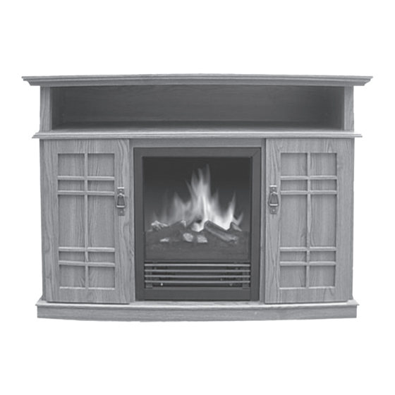
- Page 1 ELECTRIC FIREPLACE HEATER I N S T R U C T I O N M A N U A L M903L-48BHO/BDC NDF-68N ATTENTION: 1. Find a location for the fireplace heater that is protected from direct sunlight. 2. Do not plug the unit into the power outlet before you...
-
Page 2: Important Safety Instructions
S A F E T Y I N S T R U C T I O N S IMPORTANT SAFETY INSTRUCTIONS WHEN USING ELECTRICAL APPLIANCES, BASIC PRECAU- TIONS SHOULD ALWAYS BE FOLLOWED TO REDUCE THE RISK OF FIRE, ELECTRIC SHOCK, AND INJURY TO PERSONS, INCLUDING THE FOLLOWING: 40 lbs (18.2 kg) on the corner drop leaf, IMPORTANT... - Page 3 S A F E T Y I N S T R U C T I O N S 7) This electric fireplace heater is not in- 15) Avoid the use of an extension cord tended for use in bathrooms, laundry areas because the extension cord may overheat and similar indoor locations.
- Page 4 S A F E T Y I N S T R U C T I O N S This electric fireplace heater is for use on 120 volts. The cord has a plug as shown at A in illustration below. An adapter as shown at C is available for connecting three-blade grounding-type plugs to two-slot recep- tacles.
-
Page 5: Parts List
A S S E M B LY I N S T R U C T I O N S PARTS LIST: Fireplace insert A) Top panel B) Base panel C) Left outer side panel D) Right outer side panel E) Left inner side panel F) Right inner side panel G) Lower back panel H) Middle front panel... - Page 6 A S S E M B LY I N S T R U C T I O N S NOTE: Each plastic connector is pre-assem- Step 3: Attach panel C and D to base panel bled (pre-drilled) on the specific panels with [B] with 4 KD screws.
- Page 7 A S S E M B LY I N S T R U C T I O N S Step 6: Attach panel K to panels C, D, E and F with 6 KD screws. See fig. F. Fig. F Fig.
-
Page 8: Fireplace Insert Installation
A S S E M B LY I N S T R U C T I O N S Step 11: Attach 4 door hinges to Left and WARNING: Make sure the fireplace insert right door [Q and R] with 8 mounting screws controls are in the OFF position and the unit [T] (2 screws for each hinge) as shown in is NOT plugged in. -
Page 9: Operation
O P E R A T I O N 750W: For low heat function - Press this of 1875 WATTS. Once the fireplace insert has been properly connected to a grounded switch while the O/I switch is in the on electrical outlet, it is ready to operate. -
Page 10: Maintenance
M A I N T E N A N C E MAINTENANCE Step 5: Plug in the unit. WARNING: Disconnect power and unplug the power cord before attempting any main- tenance or cleaning to reduce the risk of fire, electric shock or damage to persons. The bulbs in your unit can become extremely hot. - Page 11 R E P A I R S E T fig. B 2. Drill the holes with diameter 3/4 inches (10 mm) and depth 3/4 inches (10 mm) on fig. A the mantel. Each PLASTIC CONNECTOR needs 3 holes. See Fig. C. REPAIRS If any problems are found with the origi- nal parts during mantel assembly such...
- Page 12 C L E A N I N G / W A R R A N T Y fig. E 3. Attach the SMALL L-BRACKET and lock OPTION 2: in place with SCREWS as shown in Fig. H. Use the SMALL L-BRACKETS and SCREWS CLEANING 1.
-
Page 13: Warranty
The company’s sole obligation is to repair or replace the unit. This warranty is void if in the opinion of Quality Craft the unit has been tampered with, altered, misused, damaged, abused or used with the wrong power source.
Need help?
Do you have a question about the M903L-48BHO/BDC and is the answer not in the manual?
Questions and answers