
Related Manuals for Thermal Dynamics Pak Master 100XL


Summary of Contents for Thermal Dynamics Pak Master 100XL
- Page 1 PLASMA CUTTING POWER SUPPLY ® Pak Master 100XL A-01355 Service Manual December 11, 2000 Manual No. 0-2582...
- Page 3 While the information contained in this Manual represents the Manufacturer's best judgement, the Manufacturer assumes no liability for its use. Plasma Cutting Power Supply Pak Master 100XL Service Manual Number 0-2582 Published by: Thermal Dynamics Corporation Industrial Park No.
-
Page 4: Table Of Contents
TABLE OF CONTENTS SECTION 1: GENERAL INFORMATION ....................1 1.01 Notes, Cautions and Warnings ................ 1 1.02 Important Safety Precautions ................1 1.03 Publications ..................... 2 1.04 Note, Attention et Avertissement ..............3 1.05 Precautions De Securite Importantes .............. 3 1.06 Documents De Reference ................ - Page 5 TABLE OF CONTENTS (continued) SECTION 6: PARTS LISTS ........................37 6.01 Introduction ....................37 6.02 Ordering Information ..................37 6.03 Major External Replacement Parts List ............38 6.04 Access Panel Replacement Parts List ............40 6.05 Front Panel Replacement Parts List ............. 42 6.06 Left Side Internal Component Replacement Parts List .........
-
Page 7: General Information
SECTION 1: GASES AND FUMES GENERAL INFORMATION Gases and fumes produced during the plasma cutting process can be dangerous and hazardous to your health. 1.01 Notes, Cautions and Warnings • Keep all fumes and gases from the breathing area. Throughout this manual, notes, cautions, and warnings Keep your head out of the welding fume plume. -
Page 8: Publications
• Wear dry gloves and clothing. Insulate yourself from the work piece or other parts of the welding PLASMA ARC RAYS circuit. • Repair or replace all worn or damaged parts. Plasma Arc Rays can injure your eyes and burn your skin. •... -
Page 9: Note, Attention Et Avertissement
6. ANSI Standard Z49.2, FIRE PREVENTION IN THE USE ATTENTION OF CUTTING AND WELDING PROCESSES, obtain- able from American National Standards Institute, 1430 Broadway, New York, NY 10018 Toute procédure pouvant résulter l’endommagement du matériel en cas de non- 7. AWS Standard A6.0, WELDING AND CUTTING CON- respect de la procédure en question. - Page 10 • Eloignez toute fumée et gaz de votre zone de respira- • Ne touchez jamais une pièce “sous tension” ou “vive”; tion. Gardez votre tête hors de la plume de fumée portez des gants et des vêtements secs. Isolez-vous provenant du chalumeau. de la pièce de travail ou des autres parties du circuit de soudage.
-
Page 11: Documents De Reference
ultra-violets très forts. Ces rayons d’arc nuiront à vos 1.06 Documents De Reference yeux et brûleront votre peau si vous ne vous protégez pas correctement. Consultez les normes suivantes ou les révisions les plus récentes ayant été faites à celles-ci pour de plus amples •... - Page 12 9. Norme 70 de la NFPA, CODE ELECTRIQUE NA- TIONAL, disponible auprès de la National Fire Pro- tection Association, Batterymarch Park, Quincy, MA 02269 10. Norme 51B de la NFPA, LES PROCÉDÉS DE COUPE ET DE SOUDAGE, disponible auprès de la National Fire Protection Association, Batterymarch Park, Quincy, MA 02269 11.
-
Page 13: Declaration Of Conformity
Rigorous testing is incorporated into the manufacturing process to ensure the manufactured product meets or exceeds all design specifications. Thermal Dynamics has been manufacturing products for more than 30 years, and will continue to achieve excellence in our area of manufacture. -
Page 14: Statement Of Warranty
None Warranty repairs or replacement claims under this limited warranty must be submitted by an authorized Thermal Dynamics® repair facility within thirty (30) days of the repair. No transportation costs of any kind will be paid under this warranty. Transportation charges to send products to an authorized warranty repair facility shall be the responsibility of the customer. -
Page 15: Introduction
C. Customer/Operator Responsibilities It is the customer/operators’ responsibility to maintain the equipment and peripheral Accessories provided by Thermal Dynamics in good operating order in accordance with the procedures outlined in the Operating Manual, and to protect the equipment from accidental or mali- cious damage. - Page 16 INTRODUCTION Manual 0-2582...
-
Page 17: Description
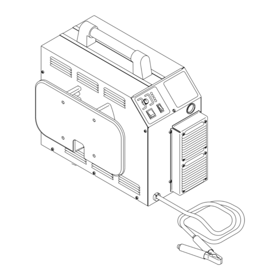
7. Cut Capacity A-01345 Torch and Leads 1 inch (25.4 mm); 1 -1/4 inch (31.8 mm) severance Figure 2-1 Pak Master 100XL Power Supply 8. Pilot Circuitry High Frequency (HF), Pulsed DC The power supply is designed to work with the Model PCH/M-100XL Plasma Torches. -
Page 18: Power Supply Options And Accessories
10. Overall Dimensions E. 575V Transformer 18.9" (480 mm) High x 13" (330 mm) Wide x 25.5" (648 This step-down transformer allows the power sup- mm) Long ply to operate with 575 VAC three-phase input power. Overall dimensions are with handle, lead wrap F. -
Page 19: Service Troubleshooting Diagnostics
SECTION 4: CAUTION SERVICE Sparks from the cutting process can cause damage TROUBLESHOOTING to coated, painted, and other surfaces such as glass, plastic and metal. DIAGNOSTICS NOTE Handle torch leads with care and protect them from 4.01 Introduction damage. A. Piloting This Section provides service diagnostics for the Pak Master 100XL Power Supply, allowing the Technician to Piloting is harder on parts life than actual cutting be-... -
Page 20: Troubleshooting Guide - General Information
Improper cutting current surements. It is helpful for solving many of the common 4. Short Torch Parts Life problems that can arise with the Pak Master 100XL Power Supply. a. Oil or moisture in air source If major complex subassemblies are faulty, the faulty sub- b. -
Page 21: Circuit Fault Isolation
C. How to use the Troubleshooting Guide Set the Power Supply controls as follows: ON/OFF switch to OFF The following information is a guide to help the Service Technician determine the most likely causes for various RUN/SET switch to SET symptoms. -
Page 22: Main Input And Internal Power Problems
4. Defective input power cable D. Main Arc Test a. Replace input power cable Press the Torch Switch to establish a pilot arc. 5. Improper input power line connections inside Power Bring the torch to within 1/8"-3/8" (3.2 - 9.5 mm) of the Supply workpiece to establish the main cutting arc, and note the following:... - Page 23 13. Faulty Gate Drive PC Board (refer to Appendix XI, 2. Gas supply not connected to unit 36 V AC Circuit Diagram) a. Connect to gas supply Measure for 36 VAC on Gate Drive PC Board from 3. Gas supply not turned on J9-1 to J9-3.
- Page 24 Pin 9 Pin 8 TP1 (GND) Logic PC Board Logic PC Board A-01404 4. Faulty Pilot Output PC Board Remove power from the power supply. Discon- Pin 13 nect J12 and J13 from the Pilot PC Board. A-01403 Check for an open between J12 pin 1 to J12 pin 3 on the Pilot Output PC Board.
-
Page 25: Pilot Arc Problems
C. AC indicator ON; Gas flows; GAS and DC 4.07 Pilot Arc Problems indicators ON; No arc in torch; No arc at spark gap on CD PC Board; CD enable indicator (D15) Locate your symptom below: on CD PC Board ON A. -
Page 26: Main Arc Problems
Pilot Output PC Board A-01400 Wire #16 Logic PC Board A-01405 Wire #17 While trying to transfer measure voltage at J17-1 to J17-2 on the Logic PC Board. Pin 1 7. Faulty Logic PC Board Measure for 15 VDC on Logic PC Board from J5-6 Pin 2 to J5-7. -
Page 27: Test Procedures
2. Faulty Logic PC Board WARNING If torch tip is off the workpiece and the drag indi- cator, D35, on the Logic PC Board is still ON, then replace the Logic PC Board Disconnect primary power at the source before as- sembling or disassembling the Power Supply, torch Logic PC Board parts, or torch and leads assemblies. - Page 28 5. Connect the volt/ohmmeter positive lead to the an- 8. Reconnect all cables to proper terminals. ode (+) of the diode and the negative lead to the cath- D. Input PC Board Test ode (-) of the diode for forward bias testing (refer to following figure).
- Page 29 If Input Bridge Diode is shorted, make the following checks with an ohmmeter at the Main Contactor: Main Contactor (MC1) M e t e r (+ ) M e t e r (-) I n d ica t io n O p e n Coil Wire #55...
- Page 30 6. Disconnect ribbon cable from the Lower FET/Heat- 13. Reconnect the ribbon cables to the Upper and sink Assembly at J6. Lower FET/Heatsink Assemblies at J6. 7. Place the front panel ON/OFF switch to ON. 14. If the front panel TEMP indicator is still ON, re- place the Logic PC Board.
- Page 31 The indicators on the Gate Drive PC Board as follows: POWER ENABLE A-01200 Logic PC Board Gate Driver PC Board A-01412 RESET I n d ic a t o r M e a n in g Indicator Meaning P o w e r E n a b le - W h e n O N P W M E n a b le re c e iv e d f ro m t h e L o g ic T orch Switch Enable - W hen O N P C B o a rd .
- Page 32 time is over the PWM Enable signal is given and the NOTE DC indicator at the front panel turns ON. When the The conformal coating must be removed from the pilot arc is established the Pilot On indicator, D33, lead of R22 for the jumper to make a good contact. turns ON.
- Page 33 Pilot Output PC Board A-01401 FET/Heatsink and Capacitor PC Board Assembly A-01414 b. Place the meter (+) lead on gate lead of Q1 and meter (-) lead on source lead of Q1. The meter should indicate approximately 2.5K ohms. 2. FET/Heatsink Output Diode Checks Spring Clip Remove input power from the unit.
- Page 34 4. FET Reset Diode Check should indicate between 0.3 to 0.6 volts using the diode function or 100K ohms using the ohms func- Use an ohmmeter set to the diode function and check tion. the reset diode per the following procedure: c.
-
Page 35: Repairs & Replacement Procedures
2. Unroll the rest of the band and peel the liner from SECTION 5: the copper foil at the opposite end. REPAIRS & REPLACEMENT 3. Attach the copper foil to a convenient and exposed electrical ground. PROCEDURES 4. Connect the equipment primary cable ground to the same electrical ground as the wrist strap. -
Page 36: Major External Parts Replacement
Before disassembling any part of the Power Supply first 5. Install the replacement Left Side Panel by revers- read the procedure for the part to be replaced, then pro- ing the above procedure noting the following: ceed with the disassembly. •... -
Page 37: Access Panel Parts Replacement
5. Remove the Pot/LED PC Board from the four stand- 5.05 Access Panel Parts offs. Replacement 6. Disconnect the connector at J14 of the Pot/LED PC NOTE Board. Refer to Section 6.04 for parts list and overall de- 7. Install the replacement Pot/LED PC Board by re- tail drawing. -
Page 38: Left Side Internal Component Parts Replacement
C. Main Contactor Replacement a. Two mounting nuts from Main Contactor As- sembly. 1. Remove the Left Side Panel per Section 5.04-B. b. Nut and wire from ground stud. 2. Note the orientation of all the wires and then dis- c. - Page 39 3. Remove the clear Input PC Board Insulator sheet. 4. Install the replacement Logic PC Board by revers- ing the above procedure. 4. Remove the two screws at 'R2' and 'G'. F. Gate Driver PC Board Replacement 5. Carefully pull the Input PC Board from the unit far enough to disconnect the wiring connections to the 1.
-
Page 40: Rear Panel Parts Replacement
3. Disconnect the output hose from the OUT side of the assembly. Connection Description 4. Install the replacement Two Stage Filter Assembly by reversing the above procedure. Main Transformer (Primary) B. Pressure Switch Replacement Main Transformer (Primary) 1. Remove the Right Side Panel per Section 5.04-C. Main Transformer (Secondary) 2. -
Page 41: Right Side Internal Component Parts Replacement
3. Disconnect the gas tube connected to the bottom of Note the routing of wires and make sure the wires the T-fitting at the Solenoid Valve Assembly. are put back in the same place when reassembling the unit. 4. Remove the Air Line Regulator Bracket per para- graph 'D' above. - Page 42 6. Install the replacement Main Transformer Assem- 8. Install the replacement Auxiliary Transformer As- bly by reversing the above procedure. sembly by reversing the above procedure noting the following: NOTE • Brown wire to 460V selector connector (J21) on The four screws securing the mounting plate to the voltage selection panel.
-
Page 43: Parts Lists
SECTION 6: PARTS LISTS 6.01 Introduction A. Parts List Breakdown The parts lists provide a breakdown of all replaceable components. The parts lists are arranged as follows: Section 6.03 Major External Replacement Parts List Section 6.04 Access Panel Replacement Parts List Section 6.05 Front Panel Replacement Parts List Section 6.06 Left Side Internal Component Re- placement Parts List... -
Page 44: Major External Replacement Parts List
6.03 Major External Replacement Parts List Item # Description Catalog # TUBE, LIFTING HANDLE, 1.125 OD, 11.85 LG 9-7505 MOUNT, LIFTING HANDLE 9-7506 COVER, LEFT SIDE Includes: 9-7610 COVER, LEFT SIDE, 2X2976 LABEL, USER WARNING, ENGLISH COVER, RIGHT SIDE Includes: 9-7609 COVER, RIGHT SIDE OVERLAY, RIGHT SIDE PANEL... - Page 45 A-01375 Manual 0-2582 PARTS LISTS...
-
Page 46: Access Panel Replacement Parts List
6.04 Access Panel Replacement Parts List Item # Description Catalog # ASSEMBLY, POT/LED PCB Replacement Kit (PC Board & Knob) 9-7014 KNOB, INNER CONCENTRIC Current Pot Shaft Diameter 1/8 inch - Order Kit 9-7014 Current Pot Shaft Diameter 1/4 inch - Knob Only 9-8007 ON/OFF ROCKER SWITCH, DPST 8-3258... - Page 47 A-01065 Manual 0-2582 PARTS LISTS...
-
Page 48: Front Panel Replacement Parts List
6.05 Front Panel Replacement Parts List Item # Description Catalog # BASE/FRONT, UNIT Includes: 9-7607 BASE/FRONT, UNIT GROUND TAG 8-4243 USA LABEL (1 3/4 X 3) 8-3216 OVERLAY, FRONT PANEL CONTACTOR, 4 POLE, 40 FLA, 120 VAC 9-7507 STRAIN REFIEF - .325-.360 DIA. 8-5537 FAN, 115V, 50/60HZ, 95/115CFM W/.187 TABS 8-3209... - Page 49 A-01376 Manual 0-2582 PARTS LISTS...
-
Page 50: Left Side Internal Component Replacement Parts List
6.06 Left Side Internal Component Replacement Parts List Item # Description Catalog # INSULATOR, INPUT PCB See Note 1 CABLE ASSEMBLY, 10 CIR RIBBON, 15"LG 9-5922 CABLE, 20 CIRCUIT RIBBON 9-7510 LOGIC CONTROL PCB ASSEMBLY 9-7601 ASSEMBLY, GATE DRIVER PCB 9-7562 ASSEMBLY, FET HEATSINK Includes: 9-7015... - Page 51 To J10 On Logic PCB To Input A-01377 Manual 0-2582 PARTS LISTS...
-
Page 52: Rear Panel Replacement Parts List
6.07 Rear Panel Replacement Parts List Item # Description Catalog # PRESSURE SWITCH-35 PSI 9-1044 VALVE, SOLENOID 1/8 NPT 8-3370 REGULATOR, AIR LINE 9-7514 FLEX CONNECTOR 8-6307 1/4 NPT STREET ELBOW 9-2184 1/8 NPT STR.TEE 8-0352 1/4-1/8 NPT REDUCER 9-2023 FITTING, 1/8 NPT X 2"... - Page 53 A-01068 Manual 0-2582 PARTS LISTS...
-
Page 54: Right Side Internal Component Replacement Parts List
6.08 Right Side Internal Component Replacement Parts List Item # Description Catalog # BULKHEAD ADAPTER, O2B - 1/8 NPT 9-4045 9/16-1/8 JAM NUT 8-2149 HEATSINK, INPUT BRIDGE See Note 1 CHASSIS, CENTER See Note 1 PANEL, PILOT ASSEMBLY MOUNTING See Note 1 BRACKET, BULKHEAD MOUNTING See Note 1 INSULATOR, BULKHEAD... - Page 55 Old Style Relay NOTE Old style panels had only holes, no studs New Style Relay A-01378 Manual 0-2582 PARTS LISTS...
-
Page 56: Options And Accessories
6.09 Options and Accessories Description Catalog # Smart Cart 7-7777 Interface Cable - For Use With Machine Torches Only 25 foot (7.62m) 8-5557 50 foot (15.24m) 8-5558 575V Transformer 9-7500 220V Single-Phase Input Power Cable 9-7512 Circle Cutting Attachment 7-7501 PARTS LISTS Manual 0-2582... -
Page 57: Appendix I: Input Wiring Requirements
APPENDIX I: INPUT WIRING REQUIREMENTS Input Power Input Current Suggested Sizes (See Notes) Voltage Freq. 1-Ph 3-Ph 1-Ph 3-Ph Fuse (Amps) Wire (AWG) Wire (Canada) (Volts) (Hz) (kVA) (kVA) (Amps) (Amps) 1-Ph 3-Ph 1-Ph 3-Ph 1-Ph 3-Ph 50/60 12.8 71.5 35.6 50/60 15.6... -
Page 58: Appendix Ii: Sequence Of Operation (Block Diagram)
APPENDIX II: SEQUENCE OF OPERATION (BLOCK DIAGRAM) ACTION ACTION ACTION ACTION ON/OFF switch Close external RUN/SET RUN/SET switch to ON. disconnect switch. switch to RUN. to SET. RESULT RESULT RESULT RESULT AC indicator blinks for 8 Power to system. Gas flow stops. Gas solenoid open, seconds then steady on. -
Page 59: Appendix Iii: Pot/Led Pc Board Layout
APPENDIX III: POT/LED PC BOARD LAYOUT A-01206 Pot/LED PC Board Signals J14-1 +10 vdc from Logic PC Board (J3-7) J14-2 Current Control to Logic PC Board (J3-8) J14-3 Return for Current Control from Logic PC Board (J3-9) J14-4 +12 VDC from Logic PC Board (J3-10) J14-5 Signal for AC OK Indicator to Logic PC Board (J3-11) J14-6... -
Page 60: Appendix Iv: Logic Pc Board Layout
APPENDIX IV: LOGIC PC BOARD LAYOUT A-01416 Logic PC Board Signals J1-1 36 VAC from Auxiliary Transformer J3-1 36 VAC to ON/OFF Switch J1-2 115 VAC from Auxiliary Transformer J3-2 36 VAC from ON/OFF Switch to Logic PC Board J1-3 Center Tap from Auxiliary Transformer J3-3 36 VAC to ON/OFF Switch... - Page 61 J4-1 36 VAC from Gate Driver PC Board (J9-1) J4-2 36 VAC to Gate Drive PC Board (J9-2) J4-3 36 VAC from Gate Drive PC Board (J9-3) J4-4 36 VAC to Gate Drive PC Board (J9-4) J4-5 Ground to Gate Drive PC Board (J9-5) J4-6 36 VAC to Gate Drive PC Board (J9-6) J4-7...
-
Page 62: Appendix V: Gate Drive Pc Board Layout
APPENDIX V: GATE DRIVE PC BOARD LAYOUT RESET TP11 TP12 POWER ENABLE TP13 A-01205 Gate Drive PC Board Signals J7-1 +12 VDC to FET PC Boards (J6-1) J7-2 Return for +12 VDC to FET PC Boards (J6-2) J7-3 PWM Output (A) to FET PC Boards (J6-3) J7-4 PWM Return to FET PC Boards (J6-4) J7-5... - Page 63 J9-1 36 VAC from Logic PC Board (J4-1) J9-2 36 VAC from Logic PC Board (J4-2) J9-3 36 VAC from Logic PC Board (J4-3) J9-4 36 VAC from Logic PC Board (J4-4) J9-5 Return from Logic PC Board (J4-5) J9-6 36 VAC from Logic PC Board (J4-6) J9-7 Return from Logic PC Board (J4-7)
-
Page 64: Appendix Vi: Pilot Output Pc Board Layout
APPENDIX VI: PILOT OUTPUT PC BOARD LAYOUT CGND A-01389 Pilot Output PC Board Signals J12-1 Torch Switch Filter in from J22-3 Torch Control J12-2 Not Used J12-3 Torch Switch Filter Return from J22-4 Torch Control J12-4 Not Used J12-5 Pilot Return Shield to J22-1 Torch Control J12-6 Torch Switch Shield to J22-2 Torch Control J12-7... - Page 65 CGND Chassis Gnd PS(-) (Stud) from Output Inductor L1 to CD Xfmr PS(-) C4 Rtn for Pilot Voltage Twisted with Pilot RTN to E23 PS(+) to E18 Upper Fet Module PS(+) to E18 Upper Fet Module From E22 to PCR Pin 2 From Pilot Choke to E20 C4 Rtn for Pilot Voltage Twisted with Pilot RTN from E8 Pilot RTN from Standoff on bulk head and Torch Cable...
-
Page 66: Appendix Vii: Cd Pc Board Layout
APPENDIX VII: CD PC BOARD LAYOUT A-01208 CD PC Board Signals J11-1 36 VAC from Logic PC Board (J5-1) J11-2 Return from Logic PC Board (J5-2) J11-3 36 VAC from Logic PC Board (J5-3) J11-4 CD Enable Signal from Logic PC Board (J5-4) J11-5 Return for CD Enable Signal from Logic PC Board (J5-5) J11-6... -
Page 67: Appendix Viii: Input Pc Board Layout
APPENDIX VIII: INPUT PC BOARD LAYOUT Component Side Of PC Board Solder Side Of PC Board A-01417 CGND Input PC Board Signals J16-1 Gate Drive Relay Rtn from Logic Board J10-1 J16-2 Gate Drive Relay Pos from Logic Board J10-2 J16-3 Not used J16-4... -
Page 68: Appendix Ix: Fet Pc Board Layout
APPENDIX IX: FET PC BOARD LAYOUT Component Side Of PC Board XFMR SEC - OUTPUT MAIN XFMR PRI MAIN XFMR PRI MAIN XFMR SEC + OUTPUT FET PCB ASSY A-00479 Solder Side Of PC Board APPENDIX Manual 0-2582... - Page 69 FET PC Board Signals (Upper and Lower Assemblies) J6-1 +12V from the Gate Drive Board upper J7-1 Lower J8-1 J6-2 +12V RTN from the Gate Drive Board upper J7-2 Lower J8-2 J6-3 Pwm Output from the Gate Drive Board upper J7-3 Lower J8-3 J6-4 Pwn Output RTN J6-2 from the Gate Drive Board upper J7-4 Lower J8-4 J6-5...
-
Page 70: Appendix X: Capacitor Pc Board Layout
APPENDIX X: CAPACITOR PC BOARD LAYOUT E12A E12B E13A E13B A-01418 E12C E13C Capacitor PC Board Signals Positve Rail to FET Board E12A Positve Rail to FET Board E12B Positve Rail to FET Board E12C Positve Rail to FET Board Negative Rail to FET Board E13A Negative Rail to FET Board... -
Page 71: Appendix Xi: Current Sensor Pc Board Layout
APPENDIX XI: CURRENT SENSOR PC BOARD LAYOUT A-01419 Current Sensor PC Board Signals J15-1 Work Cable Sense J15-2 Ground J15-3 +12 VDC Manual 0-2582 APPENDIX... -
Page 72: Appendix Xii: 36Vac Circuit Diagram
APPENDIX XII: 36VAC CIRCUIT DIAGRAM CD PC Board Logic PC 12VDC Board Circuit 36 VAC Voltage Check Circuit Auxiliary (IN) 36 VAC Transformer Outputs (IN) 115 VAC Gate Drive PC Board J3 3 A-01344 ON/OFF Switch APPENDIX Manual 0-2582... - Page 73 Manual 0-2582 APPENDIX...
-
Page 74: Appendix Xiii: System Schematic
APPENDIX XIII: SYSTEM SCHEMATIC A-01360 APPENDIX Manual 0-2582... - Page 75 11/23 EC 8055 A-01360 Manual 0-2582 APPENDIX...
Need help?
Do you have a question about the Pak Master 100XL and is the answer not in the manual?
Questions and answers