
Related Manuals for Electra Monoblock 7


Summary of Contents for Electra Monoblock 7
-
Page 1: Service Manual
Service Manual Mobile Series Indoor Units Outdoor Units Monoblock 7 SP 11 SP 11 SP 16 SP 16 REFRIGERANT R410A COOLING ONLY HEAT PUMP JANUARY 2005 CONTENTS... - Page 2 LIST OF EFFECTIVE PAGES LIST OF EFFECTIVE PAGES Note: Changes in the pages are indicated by a “Revision#” in the footer of each effected page (when none indicates no changes in the relevant page). All pages in the following list represent effected/ non effected pages divided by chapters.
-
Page 3: Table Of Contents
TABLE OF CONTENTS Table of Contents INTRODUCTION ....................1-1 PRODUCT DATA SHEET ..................2-1 RATING CONDITIONS ..................3-1 OUTLINE DIMENSIONS ..................4-1 PERFORMANCE DATA & PRESSURE CURVES ..........5-1 SOUND LEVEL CHARACTERISTICS ..............6-1 ELECTRICAL DATA ....................7-1 WIRING DIAGRAMS .....................8-1 REFRIGERATION DIAGRAMS ................9-1 10. CONTROL SYSTEM .....................10-1 11. -
Page 4: Main Features
INTRODUCTION INTRODUCTION General The Mobile range comprise the ST (cooling only) and RC (heat pump) models, as follows: Monoblock 7 R410A SP11 R410A SP16 R410A Model Mode Cooling Only √ √ √ √ √ √ Heat Pump √ √ Electric Heater √... -
Page 5: Introduction
INTRODUCTION Control Electronic model: a microprocessor indoor controller, and an infrared remote control, supplied as standard, provides complete operating function and programming. Mechanical model: Electro mechanical control . For further details please refer to the Installation and Operation Manual, Appendix A. Inbox Documentation Each unit is supplied with its own installation and operation manuals. -
Page 6: Product Data Sheet
PRODUCT DATA SHEET PRODUCT DATA SHEET R410A Model Indoor Unit Monoblock 7 R410A Model Outdoor Unit Installation Method of Pipe Characteristics Units Cooling Btu/hr 7850 Capacity 2.30 Power input 0.95 EER (Cooling) or COP(Heating) 2.42 Energy efficiency class Power supply... - Page 7 PRODUCT DATA SHEET Model Indoor Unit SP11 R410A Model Outdoor Unit SP11 R410A Installation Method of Pipe Installed already or Quick connector Characteristics Units Cooling only Cooling Heating Btu/hr 10300 10300 11600 Capacity 3.02 3.02 Power input 0.977 0.977 0.95 EER (Cooling) or COP(Heating) 3.09 3.09...
- Page 8 PRODUCT DATA SHEET Model Indoor Unit SP16 R410A Model Outdoor Unit SP16 R410A Installation Method of Pipe Installed already or Quick connector Characteristics Units Cooling only Cooling Heating Btu/hr 14230 14230 15660 Capacity 4.17 4.17 4.59 Power input 1.544 1.544 1.387 EER (Cooling) or COP(Heating) 2.70...
-
Page 9: Rating Conditions
For monoblock (EN14511) Standard condition: 35 C DB 24 C WB Application condition: 27 C DB 19 C WB Operating Limits 3.1.1 Monoblock 7 Indoor Upper limit C DB 24 C WB Cooling Lower limit C DB 15 C WB Voltage 198 –... -
Page 10: Outline Dimensions
OUTLINE DIMENSIONS OUTLINE DIMENSIONS Monoblock 7 SP 11/16 Service Manual - MOBILE Series Revision Y05-01 CONTENTS... - Page 11 PERFORMANCE DATA & PRESSURE CURVES PERFORMANCE DATA & PRESSURE CURVES Monoblock 7 5.1.1 Cooling Capacity (kW) Entering Air 15/21 17/24 19/27 21/29 23/32 24/35 WB/DB ( 2.20 2.24 2.36 2.30 2.29 2.30 1.38 1.41 1.47 1.42 1.38 1.56 0.81 0.90 0.95...
- Page 12 PERFORMANCE DATA & PRESSURE CURVES Pressure Curves 5.2.1 Cooling Suction Pressure Vs. Condensing Inlet Air Temp' Inlet Condensing Air Temp'( WB ºC) Discharge Pressure Vs. Condensing Inlet Air Temp' Temp Disch 29.9 32.7 35.5 38.3 41.1 42.5 Inlet Condensing Air Temp'( WB ºC) Revision Y05-01 Service Manual - MOBILE Series CONTENTS...
- Page 13 PERFORMANCE DATA & PRESSURE CURVES SP11 R410A 5.3.1 Cooling Capacity (kW) ENTERING AIR WB/DB ID Coil( ENTERING AIR Data DB OU Coil( 15/21 17/24 19/27 21/29 23/32 3.18 3.30 3.37 3.45 3.51 2.09 2.18 2.26 2.32 2.36 0.69 0.70 0.70 0.70 0.70 3.08...
-
Page 14: Entering Air
PERFORMANCE DATA & PRESSURE CURVES 5.3.2 Heating Capacity (kW) ENTERING AIR DB ID COIL( ENTERING WB OU COIL( 1.79 0.76 1.72 0.81 1.65 0.85 1.92 0.78 1.85 0.82 1.79 0.87 2.04 0.79 1.97 0.84 1.90 0.88 2.38 0.88 2.48 0.83 2.28 0.93 3.50... - Page 15 PERFORMANCE DATA & PRESSURE CURVES Pressure Curves 5.4.1 Cooling Discharge Pressure VS.Outdoor Temp 15/21(WB/DB ºC) 17/24(WB/DB ºC) 19/27(WB/DB ºC) 21/29(WB/DB ºC) 23/32(WB/DB ºC) Outdoor Temp.(DB Suction Pressure VS.Outdoor Temp 11.5 15/21(WB/DB ºC) 17/24(WB/DB ºC) 19/27(WB/DB ºC) 10.5 21/29(WB/DB ºC) 23/32(WB/DB ºC) Outdoor Temp.(DB Service Manual - MOBILE Series Revision Y05-01...
-
Page 16: Revision Y05-01
PERFORMANCE DATA & PRESSURE CURVES 5.4.2 Heating Discharge Pressure VS.Outdoor Temp 25 DB (ºC) 20 DB (ºC) 15 DB (ºC) Outdoor Temp.( WB Suction Pressure VS.Outdoor Temp 10.0 15 DB (ºC) 20 DB (ºC) 25 DB (ºC) Outdoor Temp.( WB Revision Y05-01 Service Manual - MOBILE Series CONTENTS... - Page 17 PERFORMANCE DATA & PRESSURE CURVES SP16 R410A 5.5.1 Cooling Capacity (kW) ENTERING AIR WB/DB ID Coil( ENTERING AIR Data DB OU Coil( 15/21 17/24 19/27 21/29 23/32 4.40 4.55 4.66 4.77 4.84 2.64 2.76 2.86 2.94 2.99 1.09 1.09 1.10 1.10 1.10 4.25...
- Page 18 PERFORMANCE DATA & PRESSURE CURVES 5.5.2 Heating Capacity (kW) ENTERING AIR DB ID COIL( ENTERING WB OU COIL( 2.41 1.11 2.32 1.18 2.23 1.24 2.59 1.14 2.50 1.20 2.41 1.26 2.75 1.15 2.66 1.22 2.57 1.29 3.21 1.28 3.35 1.21 3.08 1.36 4.73...
- Page 19 PERFORMANCE DATA & PRESSURE CURVES Pressure Curves 5.6.1 Cooling Discharge Pressure VS.Outdoor Temp 15/21(WB/DB ºC) 17/24(WB/DB ºC) 19/27(WB/DB ºC) 21/29(WB/DB ºC) 23/32(WB/DB ºC) Outdoor Temp.(DB Suction Pressure VS.Outdoor Temp 10.5 15/21(WB/DB ºC) 10.0 17/24(WB/DB ºC) 19/27(WB/DB ºC) 21/29(WB/DB ºC) 23/32(WB/DB ºC) Outdoor Temp.(DB Service Manual - MOBILE Series Revision Y05-01...
- Page 20 PERFORMANCE DATA & PRESSURE CURVES 5.6.2 Heating Discharge Pressure VS.Outdoor Temp 25 DB (ºC) 20 DB (ºC) 15 DB (ºC) Outdoor Temp.( WB Suction Pressure VS.Outdoor Temp 15 DB (ºC) 20 DB (ºC) 25 DB (ºC) Outdoor Temp.( WB 5-10 Revision Y05-01 Service Manual - MOBILE Series CONTENTS...
-
Page 21: Monoblock 7
SOUND LEVEL CHARACTERISTICS SOUND LEVEL CHARACTERISTICS Sound Pressure Level microphone Fig.1 Monoblock Soud Pressure Level Spectrum (Measured as Figure 1) Monoblock 7 SP 11 NC-70 NC-70 NC-60 NC-60 NC-50 NC-50 NC-40 NC-40 NC-30 NC-30 APPROXIMATE APPROXIMATE THRESHOLD OF THRESHOLD OF... -
Page 22: Sound Level Characteristics
SOUND LEVEL CHARACTERISTICS Fig.2 Microphone Distance from Unit Sound Pressure Level Spectrum (Measured as Figure 2) SP 11 Cooling SP 11 Heating NC-70 NC-70 NC-60 NC-60 NC-50 NC-50 NC-40 NC-40 NC-30 NC-30 APPROXIMATE APPROXIMATE THRESHOLD OF THRESHOLD OF HEARING FOR HEARING FOR NC-20 NC-20... -
Page 23: Electrical Data
ELECTRICAL DATA ELECTRICAL DATA Single Phase Units MODEL Monoblock 7 SP 11 SP 16 To indoor To indoor To indoor Power Supply 1PH-230V-50Hz 1PH-230V-50Hz 1PH-230V-50Hz Max Current, A Circuit Breaker,A Power Supply Wiring 3x1.0 mm 3x1.0 mm 3x1.5 mm (No. X Cross Section, mm 4x1.0 mm... -
Page 24: Wiring Diagrams
WIRING DIAGRAMS WIRING DIAGRAMS Monoblock 7 (Mechanical Model) Service Manual - MOBILE Series Revision Y05-01 CONTENTS... - Page 25 WIRING DIAGRAMS Monoblock 7 (Electronic Model) Revision Y05-01 Service Manual - MOBILE Series CONTENTS...
- Page 26 WIRING DIAGRAMS SP 11/16 (Electronic Model) Service Manual - MOBILE Series Revision Y05-01 CONTENTS...
- Page 27 WIRING DIAGRAMS SP 11/16 (Mechanical Model) Revision Y05-01 Service Manual - MOBILE Series CONTENTS...
-
Page 28: Refrigeration Diagrams
REFRIGERATION DIAGRAMS REFRIGERATION DIAGRAMS Heat Pump Models 9.1.1 SP11, 16 RC INDOOR UNIT Service port OUTDOOR UNIT Flexible Tube Sensor Sensor Filter Capillary Reverse tube Capillary valve Quick tube Connector Single Outdoor coil Filter Valve Indoor coil COOLING MODE *Optional O pt i onal INDOOR UNIT Service... - Page 29 REFRIGERATION DIAGRAMS Cooling Only Models 9.2.1 Monoblock 7 ST Service port Sensor Capillary tube Evaporator Filter Condenser 10.2.2 SP 11, 16 ST INDOOR UNIT OUTDOOR UNIT Flexible Tube Service port Sensor Capillary Quick tube Connector Filter Outdoor coil Indoor coil...
-
Page 30: Control System
CONTROL SYSTEM CONTROL SYSTEM 10.1 Electronic Control 10.1.1 Introduction The electronic control information is designed for service applications, and is common to the following groups of air-conditioners: • ST/ RC group -Cooling only / cooling and heating by heat pump. •... - Page 31 CONTROL SYSTEM 10.2 Legend - Alternate Current - Air-Conditioner - ON or OFF status CLOCK - ON/OFF Operation Input, (dry contact) COMP - Compressor - Central Processing Unit ELUM - Extended Louver Upward Movement (Software Jumper) E²PROM, EEP - Erase Enable Programmable Read Only Memory - Heating Element - High Pressure Control - Hardware...
- Page 32 CONTROL SYSTEM 10.3 Main PCB Controller 10-3 Service Manual - MOBILE Series Revision Y05-01 CONTENTS...
- Page 33 CONTROL SYSTEM 10.4 General functions 10.4.1 COMP operation For each Mode including POWER OFF & SB, a Min time delay of 3 min before COMP restarting, excluding DEICING Mode The Min operation time of COMP under different operating conditions is Min operation time of Operation Mode COMP...
- Page 34 CONTROL SYSTEM 10.4.5 Protections • High pressure protection is applicable to all operating modes. • Deicing control is valid in Heat and Auto Heat Mode only. • Defrosting control is valid in Dry, Cool, Heat and Auto Modes. • No reset after protection modes. 10.4.6 Thermistors operation •...
- Page 35 CONTROL SYSTEM 10.4.6.2 Cases for disabling thermistor short/disconnected detection The detection of thermistor faults (a) and (b) above, are disabled when Deicer Protection is started. The detection will be enabled again only after (1) the deicing is completed, and (2) COMP has been restarted and operated for 30 sec.
- Page 36 CONTROL SYSTEM 10.5 Cooling Mode - General Room Temperature, RT, is detected by • RAT in normal operation, or • RCT (R/C sensor) in I-FEEL mode. The resolution of RT is 1 • RT is activating COMP/WVL if (RT > SPT), and •...
- Page 37 CONTROL SYSTEM 10.5.1 Cooling Mode: Cool, Auto (at Cooling) Temp: Selected desired temperature. Fan: HIGH, MED, LOW Timer: Any I Feel: On or Off Control function Maintains room temp at desired level by comparing RT and SPT. (RT - SPT) [ COMP (WVL) OFAN...
- Page 38 CONTROL SYSTEM 10.5.2 Cooling with Autofan Mode: Cool, Auto (at cooling) Temp: Selected desired temperature Fan: Auto Timer: Any I Feel: On or Off Control function Maintains room temp at desired level and controls the IFAN speed for optimal comfort. (RT - SPT) [ COMP (WVL)
-
Page 39: Heating Mode
CONTROL SYSTEM 10.6 Heating Mode 10.6.1 Heating Mode - General • In heating Mode, temp. compensation schedule will be activated for wall mounted units. Add to SPT SPT [ I-FEEL ON I-FEEL OFF 18 ≤ SPT ≤ 27 27 < SPT ≤ 30 Notes : •... - Page 40 CONTROL SYSTEM 10.6.3 HE operation • For all Groups, HE can be ON only when IFAN is ON. • For all Groups, HE switches to OFF when ICT > 50 c, and is activated again when ICT ≤ 45 • In SH or RC group, HE operation is limited by the following graph: General : ICT [...
- Page 41 CONTROL SYSTEM 10.6.4 Heating, RC or SH Group Mode: Heat, Auto (at heating) Temp: Selected desired temperature Fan: HIGH, MED, LOW Timer: Any I Feel: On or Off Control function Maintains room temp. at desired level by comparing RAT or RCT to SPT. (RT - SPT) [ COMP (WVL)
- Page 42 CONTROL SYSTEM 10.6.5 Heating, RC or SH Group with Autofan Mode: Heat, Auto (at heating) Temp: Selected desired temperature Fan: Auto Timer: Any I Feel: On or Off Control function Maintains room temp at desired level by controlling COMP, IFAN and OFAN. (RT - SPT) [ COMP (WVL)
- Page 43 CONTROL SYSTEM 10.6..6 OFAN operation is controlled by the graph below when 1. (RAT ≥ SPT – 2 c), AND 2. (ICT ≥ 45 c), AND 3. (COMP is ON) Otherwise, OFAN runs together with COMP. OCT [ OFAN 10-14 Revision Y05-01 Service Manual - MOBILE Series CONTENTS...
- Page 44 CONTROL SYSTEM 10.7 Automatic Cooling or Heating 10.7.1 Automatic Cooling or Heating - General • Switching-temperature between Cooling and Heating is SPT ± 3 • Autofan in Automatic Cooling and Heating Mode will activate “Cooling with Autofan Mode” and “Heating with Autofan Mode” respectively. •...
- Page 45 CONTROL SYSTEM 10.7.2 Auto Cooling or Heating, RC or SH Groups Mode: Auto Temp: Selected desired temperature Fan: Timer: Any I Feel: On or Off Control function Maintains room temp at desired level by selecting between cooling and heating modes. (RT - SPT) [ Auto Heat Mode Auto Cool Mode...
- Page 46 CONTROL SYSTEM 10.8 Dry Mode 10.8.1 Dry, ST or RC group Mode: Dry Temp: Selected desired temp Fan: Low (automatically selected by software) Timer: Any I FEEL: Control function Reduce room humidity with minimum temp. fluctuations by operating in Cool Mode with low speed IFAN.
- Page 47 CONTROL SYSTEM 10.9 Protection 10.9.1 Cooling Mode Protections Indoor Coil Defrost Mode: Cooling, Dry, Auto Temp: Selected desired temp. Fan: Timer: Any I Feel: On or Off Control Function Protect the indoor coil from ice formation at low ambient temperature. ICT [ OFAN COMP...
- Page 48 CONTROL SYSTEM 10.9.2 High Pressure Protection Mode: (Auto) Cooling or Dry Temp: Selected desired temp. Fan: Timer: Any I Feel: On or Off Control Function To protect the COMP from the high pressure built-up in the outdoor coil during normal cooling operation, by switching OFF the IFAN and COMP.
- Page 49 CONTROL SYSTEM 10.9.3 Heating Mode Protections Outdoor coil Deicing (excluding RH Group) Mode: Heating, Auto (at heating) Temp: Selected desired Temp Fan: Timer: Any I FEEL: Any Control function Protects the Outdoor coil from ice formation by controlling COMP & RV operation. Scope This new deicer is designed to operate at extreme temp conditions.
- Page 50 CONTROL SYSTEM Deicing procedure OCT [ (DDT) 3 min 3 min max 12 min. COMP DI (note 1) DI (note 2) OFAN IFAN is forced to Low Speed IFAN HEs are forced ON IFAN Note 3 HEs are forced OFF OPER BLINK Notes :...
- Page 51 CONTROL SYSTEM 10.9.4 High pressure protection (excluding RH Group) Mode: (Auto) Heating Fan: Timer: Any I Feel: On or Off Control Function Protect the Compressor from high pressure by switching OFF the OFAN and COMP. ICT [ For all models except WAX For WAX model COMP COMP is forced OFF...
- Page 52 CONTROL SYSTEM 10.9.5 Indoor Condensation Pump (ICP) Operation and Overflow Protection (PXD, P2000 and MBX Models) Mode: Cooling, Dry, Auto (at Cooling) Temp: Desired temp selected Fan: Timer: I Feel: On or Off Control function: To prevent the overflow of condensed water by turning ON the ICP. Water Level LEVEL4 LEVEL2&3...
- Page 53 CONTROL SYSTEM 10.9.6 Outdoor condensation pump (P2000 Model) Mode: Cooling, Auto (at Cooling), Dry. Temp: Selected Desired temp. Fan: Timer: Any Feel: On or Off Control Function Pumps condensed water from Indoor unit to Outdoor unit. Outdoor Condensation Pump Control The Outdoor pump relay is activated in parallel with the COMP at: Cooling, Dry, and Auto cooling as described in the following table: COMP...
- Page 54 CONTROL SYSTEM 10.10 Timer Mode: Any Temp. Selected desired temp Fan: Timer: Timer On, Timer Off I Feel: On or Off Control function • Starts or stops the unit operation after pre-set time. If RC-1 is used, the timer setting will be (0.5 - 24 Hr) from the moment the timer is set. The minimum resolution is 30 minutes.
-
Page 55: Forced Operation
CONTROL SYSTEM 10.11 Forced Operation Forced operation allows units to start, stop and operate in Cooling or Heating in pre-set temperature according to the following table: Forced operation Pre-set Temp for ; Pre-set Temp for : mode MBX, P2000, PRX, FCD, RWK, ELD, ECC, PX, PXD models WAX, WMF, WMN, WNG... - Page 56 CONTROL SYSTEM 10.12 Sleep Mode Mode: Any Temp: Set – desired temperature selected Fan: Timer: Interact with Sleep Timer as described in sect 12.2 I Feel: On or Off The Sleep mode is activated by using the sleep button on the R/C. In Sleep Mode, the unit will automatically adjust the SPT to turn up/down the room temperature (RT) gradually to provide maximum comfort to the user in sleep.
- Page 57 CONTROL SYSTEM 10.12.2 Time adjustment in Sleep Mode The user can make use of the Off-Timer to extend the Sleep Time from 7 hours to 12 hour (max). The operation of the new “Extended Sleep Mode” is illustrated by the graphs below.
- Page 58 CONTROL SYSTEM 10.13 Clogged Air Filter Filter LED ON after 512 HR. Filter LED is turned OFF, and the Filter Timer is restarted by pressing the reset button. 10-29 Service Manual - MOBILE Series Revision Y05-01 CONTENTS...
- Page 59 CONTROL SYSTEM 10.14 Controller Self-Test Procedure 10.14.1 By Shorting Test Jumper J1 SELF-TEST FLOW CHART FOR CONTROLLER (VERSION 4V5 OR HIGHER) SHORT JUMPER Step 1 RC/ST TEST (CONTROL PCB) MODEL CONFIGURATION TEST PRESS ON Step 2 POWER BUTTON STEP MOTOR TEST FREQUENCY TEST STANDBY...
- Page 60 CONTROL SYSTEM 10.14.2 By Remote Control Settings: 1: TURNING ON THE POWER. Turn ON the power, make sure that the unit is in operation. STEP 2 : ENABLE SELF-TEST MODE • Use the remote control to send the first settings to display / indoor unit HEAT mode, HIGH IFAN, set temperature to 16 ºC, no I-FEEL Sleep or any other timer settings are needed.
- Page 61 CONTROL SYSTEM STEP 4 : AUTO LED WALK TEST. • All the LEDS will turn OFF. • All the LEDS will turn ON for 1 second one by one in the following sequence: STAND-BY OPERATE TIMER FILTER COOL HEAT. • In PRX all the LEDS will turn ON for 1 second one by one in the following sequence : 18 °c 20 °c...
- Page 62 CONTROL SYSTEM Fail condition: 0 sec - STAND-BY is turned ON 3 sec - STAND-BY, OPER, TIMER and FILTER are turned ON • When the timing reset test is completed, the next test will start automatically. STEP 9: MEMORY TEST (EEPROM) •...
- Page 63 CONTROL SYSTEM 10.15 On Unit Indicators and Controls Lights up when the Air Conditioner is connected to power and STAND BY ready to receive the R/C commands INDICATOR Blinks continuously in case of any thermistor failure. Lights up during operation. Blinks for 300 ms, to announce that a R/C infrared signal has been received and stored.
- Page 64 CONTROL SYSTEM 10.16 Clock Random Delay From 0 to 2.5 seconds Clock Switch Open Clock Switch close The Clock is activate according to the following table: A/C STATE CLOCK STATE CLOCK ACTION A/C NEW STATE (clock is changed) (after clock is changed) before clock is changed) before clock is changed) OFF by...
- Page 65 CONTROL SYSTEM 10.17 System Diagnostics Pressing Mode button for 5-10 seconds in SB or any other operation mode will activate diagnostic mode by the acknowledgment of 3 short beeps and lighting of COOL and HEAT LEDs. In diagnostic mode, system problems will be indicated by blinking of Heat & Cool LEDs. The coding method will be as follow: Heat led will blink 5 times in 5 seconds, and then will be shut off for the next 5 seconds.
-
Page 66: Troubleshooting
TROUBLESHOOTING TROUBLESHOOTING MOBILE SPLIT - TROUBLE SHOOTING CONTROLS AND REFRIGERATION CONNECT THE AIR CONDITIONER TO POWER SUPPLY. IS THERE CORRECT VOLTAGE BETWEEN THE DOES THE STANDBY LINE AND NEUTRAL REPLACE MAIN P.C.B OR DISPLAY P.C.B INDICATOR LIGHT UP? TERMINALS ON THE MAIN P.C.B? START THE UNIT BY THE REMOTE START THE UNIT BY THE... - Page 67 TROUBLESHOOTING PORTABLE / MOBILE SPLIT - COOLING TROUBLE SHOOTING CONTROLS AND REFRIGERATION CONNECT THE AIR CONDITIONER TO POWER SUPPLY. IS THERE CORRECT VOLTAGE DOES THE STANDBY BETWEEN THE LINE AND REPLACE MAIN P.C.B OR DISPLAY P.C.B INDICATOR LIGHT UP? NEUTRAL TERMINALS ON THE MAIN P.C.B? START THE COOL MODE BY THE START THE COOL MODE...
- Page 68 TROUBLESHOOTING PORTABLE - COOLING - TROUBLE SHOOTING CONTROLS AND REFRIGERATION CONNECT THE AIR CONDITIONER TO POWER SUPPLY. IS THERE CORRECT VOLTAGE BETWEEN THE DOES THE STANDBY LINE AND NEUTRAL REPLACE MAIN P.C.B OR DISPLAY P.C.B INDICATOR LIGHT UP? TERMINALS ON THE MAIN P.C.B? START THE UNIT BY THE REMOTE START THE UNIT BY THE...
-
Page 69: Exploded Views And Spare Parts Lists
EXPLODED VIEWS AND SPARE PARTS LISTS EXPLODED VIEWS AND SPARE PARTS LISTS 12.1 Monoblock 7M Service Manual - MOBILE Series Revision Y05-01 12-1 CONTENTS... - Page 70 EXPLODED VIEWS AND SPARE PARTS LISTS 12.2 Monoblock 7M 1 4 1 4 12-2 Revision Y05-01 Service Manual - MOBILE Series CONTENTS...
- Page 71 EXPLODED VIEWS AND SPARE PARTS LISTS 12.3 Monoblock 7M 16 16 2 3 2 3 3 3 3 3 1 2 / 0 2 AIR CONDITIONING SHENZHEN LTD. 2 4 2 4 2 8 2 8 Service Manual - MOBILE Series Revision Y05-01 12-3 CONTENTS...
- Page 72 EXPLODED VIEWS AND SPARE PARTS LISTS 12.4 Monoblock 7M 3 6 3 6 4 0 4 0 4 2 4 2 45 45 49 49 12-4 Revision Y05-01 Service Manual - MOBILE Series CONTENTS...
- Page 73 EXPLODED VIEWS AND SPARE PARTS LISTS 12.5 Monoblock 7M Part No. Description 412169 Blade 1 EL10 412170 Blade 2 EL10 4523249 Head assy. M7M ACE 412031 HEAD P2000 MB AIRWELL 412165 Display Board PCB-M 901-201-04 412269 Thermostat 412224 Select Switch 16A 412230 Control Tray Mobile M 412177...
- Page 74 EXPLODED VIEWS AND SPARE PARTS LISTS 14.6 Monoblock 7E 12-6 Revision Y05-01 Service Manual - MOBILE Series CONTENTS...
- Page 75 EXPLODED VIEWS AND SPARE PARTS LISTS 14.7 Monoblock 7E Service Manual - MOBILE Series Revision Y05-01 12-7 CONTENTS...
- Page 76 EXPLODED VIEWS AND SPARE PARTS LISTS 14.8 Monoblock 7E 12-8 Revision Y05-01 Service Manual - MOBILE Series CONTENTS...
- Page 77 EXPLODED VIEWS AND SPARE PARTS LISTS 14.9 Monoblock 7E Service Manual - MOBILE Series Revision Y05-01 12-9 CONTENTS...
- Page 78 EXPLODED VIEWS AND SPARE PARTS LISTS 14.10 Monoblock 7E Part No. Description 412226 Cotrol Door P2000E Printed 412163 Display Board PCB-E 901-201-02 4526469 RC5 ST EL10 436052 Motor step 4523087 Head assy M7E Airwell 412169 Blade 1 EL10 412170 Blade 2 EL10 4522085 Pump assy 412047...
- Page 79 EXPLODED VIEWS AND SPARE PARTS LISTS 14.11 SP11E RC QC Service Manual - MOBILE Series Revision Y05-01 12-11 CONTENTS...
- Page 80 EXPLODED VIEWS AND SPARE PARTS LISTS 14.12 SP11E RC QC 12-12 Revision Y05-01 Service Manual - MOBILE Series CONTENTS...
- Page 81 EXPLODED VIEWS AND SPARE PARTS LISTS 14.13 SP11E RC QC Service Manual - MOBILE Series Revision Y05-01 12-13 CONTENTS...
- Page 82 EXPLODED VIEWS AND SPARE PARTS LISTS 14.14 SP11E RC QC 12-14 Revision Y05-01 Service Manual - MOBILE Series CONTENTS...
- Page 83 EXPLODED VIEWS AND SPARE PARTS LISTS 14.15 SP11E RC QC Part No. Description 410999 Rear Guard 16 EL10 410915 Condenser Top Cover Painting EL10 SP16 410914 Flex.Hose Support Cover Painting EL10 452973800 Condenser / SP11 R410A 410040 Outdoor Fan Motor A4E360-AE19-16 410542 Condenser Housing EL10 410942...
- Page 84 EXPLODED VIEWS AND SPARE PARTS LISTS 14.16 SP11E RC 12-16 Revision Y05-01 Service Manual - MOBILE Series CONTENTS...
- Page 85 EXPLODED VIEWS AND SPARE PARTS LISTS 14.17 SP11E RC Service Manual - MOBILE Series Revision Y05-01 12-17 CONTENTS...
- Page 86 EXPLODED VIEWS AND SPARE PARTS LISTS 14.18 SP11E RC 12-18 Revision Y05-01 Service Manual - MOBILE Series CONTENTS...
- Page 87 EXPLODED VIEWS AND SPARE PARTS LISTS 14.19 SP11E RC Part No. Description 410999 Rear Guard 16 EL10 410915 Condenser Top Cover Painting EL10 SP16 410914 Flex.Hose Support Cover Painting EL10 452973800 Condenser / SP11 R410A 410040 Outdoor Fan Motor A4E360-AE19-16 410542 Condenser Housing EL10 410942...
- Page 88 EXPLODED VIEWS AND SPARE PARTS LISTS 14.20 SP11E ST QC 12-20 Revision Y05-01 Service Manual - MOBILE Series CONTENTS...
- Page 89 EXPLODED VIEWS AND SPARE PARTS LISTS 14.21 SP11E ST QC Service Manual - MOBILE Series Revision Y05-01 12-21 CONTENTS...
- Page 90 EXPLODED VIEWS AND SPARE PARTS LISTS 12.22 SP11E ST QC 12-22 Revision Y05-01 Service Manual - MOBILE Series CONTENTS...
- Page 91 EXPLODED VIEWS AND SPARE PARTS LISTS 12.23 SP11E ST QC Part No. Description 410999 Rear Guard 16 EL10 410915 Condenser Top Cover Painting EL10 SP16 410914 Flex.Hose Support Cover Painting EL10 452973800 Condenser / SP11 R410A 410040 Outdoor Fan Motor A4E360-AE19-16 410542 Condenser Housing EL10 410942...
- Page 92 EXPLODED VIEWS AND SPARE PARTS LISTS 12.24 SP11E ST 12-24 Revision Y05-01 Service Manual - MOBILE Series CONTENTS...
- Page 93 EXPLODED VIEWS AND SPARE PARTS LISTS 12.25 SP11E ST Service Manual - MOBILE Series Revision Y05-01 12-25 CONTENTS...
- Page 94 EXPLODED VIEWS AND SPARE PARTS LISTS 12.25 SP11E ST 12-26 Revision Y05-01 Service Manual - MOBILE Series CONTENTS...
- Page 95 EXPLODED VIEWS AND SPARE PARTS LISTS 12.26 SP11E ST Part No. Description 410999 Rear Guard 16 EL10 410915 Condenser Top Cover Painting EL10 SP16 410914 Flex.Hose Support Cover Painting EL10 452973800 Condenser / SP11 R410A 410040 Outdoor Fan Motor A4E360-AE19-16 410542 Condenser Housing EL10 410942...
- Page 96 EXPLODED VIEWS AND SPARE PARTS LISTS 12.28 SP11M ST QC 12-28 Revision Y05-01 Service Manual - MOBILE Series CONTENTS...
- Page 97 EXPLODED VIEWS AND SPARE PARTS LISTS 12.28 SP11M ST QC Service Manual - MOBILE Series Revision Y05-01 12-29 CONTENTS...
- Page 98 EXPLODED VIEWS AND SPARE PARTS LISTS 12.30 SP11M ST QC 12-30 Revision Y05-01 Service Manual - MOBILE Series CONTENTS...
- Page 99 EXPLODED VIEWS AND SPARE PARTS LISTS 12.31 SP11M ST QC Service Manual - MOBILE Series Revision Y05-01 12-31 CONTENTS...
- Page 100 EXPLODED VIEWS AND SPARE PARTS LISTS 12.32 SP11M ST QC Part No. Description 410999 Rear Guard 16 EL10 410915 Condenser Top Cover Painting 410914 Flex.Hose Support Cover 452973800 Condenser / SP11 R410A 410040 Outdoor Fan Motor A4E360-AE19-16 410542 Condenser Housing EL10 410942 Drain Pan PSX 16 COLOR: EL10 410041...
- Page 101 EXPLODED VIEWS AND SPARE PARTS LISTS 12.33 SP11M ST Service Manual - MOBILE Series Revision Y05-01 12-33 CONTENTS...
- Page 102 EXPLODED VIEWS AND SPARE PARTS LISTS 12.34 SP11M ST 12-34 Revision Y05-01 Service Manual - MOBILE Series CONTENTS...
- Page 103 EXPLODED VIEWS AND SPARE PARTS LISTS 12.35 SP11M ST Service Manual - MOBILE Series Revision Y05-01 12-35 CONTENTS...
- Page 104 EXPLODED VIEWS AND SPARE PARTS LISTS 12.36 SP11M ST Part No. Description 410999 Rear Guard 16 EL10 410915 Condenser Top Cover Painting EL10 SP16 410914 Flex.Hose Support Cover Painting EL10 452973800 Condenser / SP11 R410A 410040 Outdoor Fan Motor A4E360-AE19-16 410542 Condenser Housing EL10 410942...
- Page 105 EXPLODED VIEWS AND SPARE PARTS LISTS 12.37 SP16E RC QC Service Manual - MOBILE Series Revision Y05-01 12-37 CONTENTS...
- Page 106 EXPLODED VIEWS AND SPARE PARTS LISTS 12.38 SP16E RC QC 12-38 Revision Y05-01 Service Manual - MOBILE Series CONTENTS...
- Page 107 EXPLODED VIEWS AND SPARE PARTS LISTS 12.39 SP16E RC QC Service Manual - MOBILE Series Revision Y05-01 12-39 CONTENTS...
- Page 108 EXPLODED VIEWS AND SPARE PARTS LISTS 12.40 SP16E RC QC 12-40 Revision Y05-01 Service Manual - MOBILE Series CONTENTS...
- Page 109 EXPLODED VIEWS AND SPARE PARTS LISTS 12.41 SP16E RC QC Part No. Description 410999 Rear Guard 16 EL10 410915 Condenser Top Cover Painting EL10 SP16 410914 Flex.Hose Support Cover Painting EL10 453107900 3-Row Condenser / SP16 R410A 410040 Outdoor Fan Motor A4E360-AE19-16 410542 Condenser Housing EL10 410942...
- Page 110 EXPLODED VIEWS AND SPARE PARTS LISTS 12.42 SP16E RC 12-42 Revision Y05-01 Service Manual - MOBILE Series CONTENTS...
- Page 111 EXPLODED VIEWS AND SPARE PARTS LISTS 12.43 SP16E RC Service Manual - MOBILE Series Revision Y05-01 12-43 CONTENTS...
- Page 112 EXPLODED VIEWS AND SPARE PARTS LISTS 12.37 SP16E RC 12-44 Revision Y05-01 Service Manual - MOBILE Series CONTENTS...
- Page 113 EXPLODED VIEWS AND SPARE PARTS LISTS 12.37 SP16E RC Part No. Description 410999 Rear Guard 16 EL10 410915 Condenser Top Cover Painting EL10 SP16 410914 Flex.Hose Support Cover Painting EL10 453107900 3-Row Condenser / SP16 R410A 410040 Outdoor Fan Motor A4E360-AE19-16 410542 Condenser Housing EL10 410942...
- Page 114 EXPLODED VIEWS AND SPARE PARTS LISTS 12.46 SP16E ST QC 12-46 Revision Y05-01 Service Manual - MOBILE Series CONTENTS...
- Page 115 EXPLODED VIEWS AND SPARE PARTS LISTS 12.47 SP16E ST QC Service Manual - MOBILE Series Revision Y05-01 12-47 CONTENTS...
- Page 116 EXPLODED VIEWS AND SPARE PARTS LISTS 12.48 SP16E ST QC 12-48 Revision Y05-01 Service Manual - MOBILE Series CONTENTS...
- Page 117 EXPLODED VIEWS AND SPARE PARTS LISTS 12.49 SP16E ST QC Part No. Description 410999 Rear Guard 16 EL10 410915 Condenser Top Cover Painting EL10 SP16 410914 Flex.Hose Support Cover Painting EL10 453107900 3-Row Condenser / SP16 R410A 410040 Outdoor Fan Motor A4E360-AE19-16 410542 Condenser Housing EL10 410942...
- Page 118 EXPLODED VIEWS AND SPARE PARTS LISTS 12.50 SP16E ST 12-50 Revision Y05-01 Service Manual - MOBILE Series CONTENTS...
- Page 119 EXPLODED VIEWS AND SPARE PARTS LISTS 12.51 SP16E ST Service Manual - MOBILE Series Revision Y05-01 12-51 CONTENTS...
- Page 120 EXPLODED VIEWS AND SPARE PARTS LISTS 12.52 SP16E ST 12-52 Revision Y05-01 Service Manual - MOBILE Series CONTENTS...
- Page 121 EXPLODED VIEWS AND SPARE PARTS LISTS 12.53 SP16E ST Part No. Description 410999 Rear Guard 16 EL10 410915 Condenser Top Cover Painting EL10 SP16 410914 Flex.Hose Support Cover Painting EL10 453107900 3-Row Condenser / SP16 R410A 410040 Outdoor Fan Motor A4E360-AE19-16 410542 Condenser Housing EL10 410942...
- Page 122 EXPLODED VIEWS AND SPARE PARTS LISTS 12.54 SP16M ST QC 12-54 Revision Y05-01 Service Manual - MOBILE Series CONTENTS...
- Page 123 EXPLODED VIEWS AND SPARE PARTS LISTS 12.55 SP16M ST QC Service Manual - MOBILE Series Revision Y05-01 12-55 CONTENTS...
- Page 124 EXPLODED VIEWS AND SPARE PARTS LISTS 12.56 SP16M ST QC 12-56 Revision Y05-01 Service Manual - MOBILE Series CONTENTS...
- Page 125 EXPLODED VIEWS AND SPARE PARTS LISTS 12.57 SP16M ST QC Service Manual - MOBILE Series Revision Y05-01 12-57 CONTENTS...
- Page 126 EXPLODED VIEWS AND SPARE PARTS LISTS 12.58 SP16M ST QC Part No. Description 410999 Rear Guard 16 EL10 410915 Condenser Top Cover Painting EL10 SP16 410914 Flex.Hose Support Cover Painting EL10 453107900 3-Row Condenser / SP16 R410A 410040 Outdoor Fan Motor A4E360-AE19-16 410542 Condenser Housing EL10 410942...
- Page 127 EXPLODED VIEWS AND SPARE PARTS LISTS 12.59 SP16M ST Service Manual - MOBILE Series Revision Y05-01 12-59 CONTENTS...
- Page 128 EXPLODED VIEWS AND SPARE PARTS LISTS 12.60 SP16M ST 12-60 Revision Y05-01 Service Manual - MOBILE Series CONTENTS...
- Page 129 EXPLODED VIEWS AND SPARE PARTS LISTS 12.61 SP16M ST Service Manual - MOBILE Series Revision Y05-01 12-61 CONTENTS...
- Page 130 EXPLODED VIEWS AND SPARE PARTS LISTS 12.62 SP16M ST Part No. Description 410999 Rear Guard 16 EL10 410915 Condenser Top Cover Painting EL10 SP16 410914 Flex.Hose Support Cover Painting EL10 453107900 3-Row Condenser / SP16 R410A 410040 Outdoor Fan Motor A4E360-AE19-16 410542 Condenser Housing EL10 410942...
-
Page 131: Appendix A
APPENDIX A APPENDIX A INSTALLATION AND OPERATION MANUAL ► INSTALLATION AND OPERATION MANUAL MONOBLOCK 7 ST (E/M) ► INSTALLATION AND OPERATION MANUAL SP11/16 ST/RC (E/M) 13-1 Service Manual - MOBILE Series Revision Y05-01 CONTENTS... - Page 132 APPENDIX A...
- Page 133 APPENDIX A...
- Page 134 APPENDIX A...
- Page 135 APPENDIX A...
- Page 136 APPENDIX A...
- Page 137 APPENDIX A...
- Page 138 APPENDIX A...
- Page 139 APPENDIX A...
- Page 140 APPENDIX A...
- Page 141 APPENDIX A...
- Page 142 APPENDIX A...
- Page 143 APPENDIX A...
- Page 144 APPENDIX A...
- Page 145 APPENDIX A...
- Page 146 APPENDIX A...
- Page 147 APPENDIX A...
- Page 148 APPENDIX A...
- Page 149 APPENDIX A...
- Page 150 APPENDIX A...
- Page 151 APPENDIX A...
- Page 152 APPENDIX A...
- Page 153 APPENDIX A...
- Page 154 APPENDIX A...
- Page 155 APPENDIX A...
- Page 156 APPENDIX A...
- Page 157 APPENDIX A...
- Page 158 F R A N G A I S CLIMATISEUR SPLIT MOBILE MOBILE SPLIT AIR CONDITIONER E N G L I S H D E U T S C H MOBILE SPLIT-KLIMAGER?TE CLIMATIZZATORE PORTATILE SPLIT I T A L I A N O E S P A Y O L ACONDICIONADO DE AIRE PORT;TIL Y PARTIDO NEDERLANDS...
- Page 159 English MOBILE SPLIT AIR CONDITIONER ELECTRONIC / REMOTE CONTROL ELECTRO MECHANICAL CONTROL INSTALLATION AND OPERATING INSTRUCTIONS APPENDIX A...
- Page 160 CONTENTS INTRODUCTION..............................IMPORTANT NOTES ............................... DESCRIPTION................................. ACCESSORIES ............................... INSTALLATION................................ INSTALLATION OF OUTDOOR UNIT ........................ELECTRICAL CONNECTION ..........................OPERATION-ELECTRONIC MODEL (With remote control) .................. MODES OF OPERATION, FUNCTIONS AND FEATURES ..................USE OF WIRELESS REMOTE CONTROL ......................ON-UNIT INDICATORS AND CONTROLS-(ELECTRONIC MODES) ...............
-
Page 161: Introduction
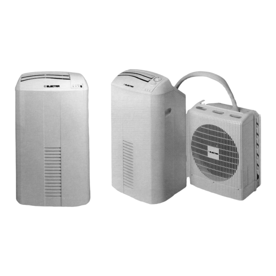
INTRODUCTION This new split mobile air conditioner consists in an indoor and outdoor unit, interconnected by a flexible hose. The indoor unit is equipped with four castors for easy mobility. The air conditioner you have purchased is a factory-chagred and ready for use. No special installation is required;... -
Page 162: Description
DESCRIPTION Electro-Mechanical models 3.1 KW (R407C) Electronic models 3.1 KW (R407C) Figure 1: Indoor and Outdoor Unit components Description (Front) Electro-Mechanical models 4.1 KW (R22/R410A) Electronic models 4.1 KW (R22/R410A) 3.1 KW (R410A) 3.1 KW (R410A) Figure 2: Indoor and Outdoor Unit components Description (Front) 1. -
Page 163: Accessories
Models 3.1 KW (R407C) Models 3.1 KW (R407C) - With Quick Connectors Models 4.1 KW (R22/R410A) - With Quick Connectors Models 4.1 KW (R22/R410A) 3.1 KW (R410A) - With Quick Connectors 3.1 KW (R410A) Figure 3: Indoor and Outdoor Unit components Description (Back) 7. -
Page 164: Installation
INSTALLATION This mobile split air conditioner can be installed by the customer, as follows: Choose an appropriate place for the air conditioner indoor unit near an exterior opening (window or door). A grounded 230 electrical outlet should be within 2.5 meters of the indoor unit. Determine whether the outdoor unit is to be suspended from the window of the wall, or placed on the floor near a doorway. -
Page 165: Installation Of Outdoor Unit
INSTALLATION OF OUTDOOR UNIT (See Figure 6,7,8) A standard kit (Figure 8), supplied with the air conditioner for suporting the outdoor unit, makes it possible to mount it either from a window sill (Figure 6) or on the wall (Figure 7), refer to Figure 8 for reference numbers in the following steps. - Page 166 Figure 9 Prepare a slot in the lower part of door or window frame for the interconnecting hose location (see Figure 9). Pass the interconnecting hose which contains the refrigerant tubing, cable and drain tube through a window or door opening. Be sure not to subject the interconnecting hose to any over-stress, avoid sharp bends or forced twisting.
- Page 167 APPLICATION OF QUICK CONNECTORS (OPTIONAL) The quick disconnect feature is used when installing the flexible interconnecting hose through a window or a wall. It enables temporary separation between indoor and outdoor units when passing the hose through and opening in an external wall.
-
Page 168: Electrical Connection
CONNECTING THE UNITS (See Figures 12 and 13) After locating outdoor and indoor unit in their respective places, perform the following steps to reconnect between the two units: Remove protection plugs (16), (18) and covers (15), (17) from their respective connectors (see Figure STEP 1. - Page 169 QUICK CONNECTORS APPLICATION (OPTIONAL) English 10 APPENDIX A...
-
Page 170: Operation-Electronic Model (With Remote Control)
OPERATION - ELECTRONIC MODEL (With remote control) In order to obtain maximum comfort and economical operation, please make sure to: Doors and windows of room to be conditioned are closed. Air outlet and inlet openings on the unit are free of any obstruction. Shade the room from direct sunrays and avoid excessive sources of heat in the room. - Page 171 VERTICAL AIR SWING (OPTIONAL) Automatic swing of air supply in a vertical direction. The flaps automatically move in upward and downward directions to disperse the conditioned air evenly throughout the room. FILTER AND WATER OVERFLOW INDICATION (see indicator C on figure 15) Filter indicator on the indoor unit display is turned on when the filter requires cleaning.
-
Page 172: Use Of Wireless Remote Control
USE OF WIRELESS REMOTE CONTROL THE WIRELESS REMOTE CONTROL BRINGS ALL FUNCTIONS TO YOUR FINGERTIPS. PRIOR TO OPERATION Prior to operating your air conditioner, make sure that: The unit is properly connected to the power supply. The red tab protecting the remote control battery has been removed. -
Page 173: On-Unit Indicators And Controls-(Electronic Modes)
ON-UNIT INDICATORS AND CONTROLS - (ELECTRONIC MODES) (See Figure 15) A. TIMER INDICATOR Lights up during TIMER and SLEEP operation. B. OPERATION INDICATOR Lights up during operation. Blinks to announce that the remote control infrared signal has been received and stored. Blinks continuously when compressor operates in its high-pressure protection mode. - Page 174 REMOTE CONTROL (See figure 16) START/STOP button Operation MODE selection button FAN SPEED and AUTO FAN button Temperature set UP button (+) Temperature set DOWN button (-) SLEEP button Automatic Vertical Air Swing button TIMER select button TIMER set up button (+) TIMER set down button (-) LCD display Infrared signal transmitter...
- Page 175 OPERATION PROCEDURE (See figs. 15 & 16) TURNING ON THE AIR CONDITIONER Press START/STOP button (1) to turn on the air conditioner. Operation Indicator (B) on the air conditioner will light up, indicating that the unit is in operation. Note that the LCD operation display (11) will always show the last mode of operation and the previous function used.
- Page 176 AUTOMATIC VERTICAL AIR SWING Press button (7) to activate the auto air swing. Press the button again to deactivate this function. HEATING OPERATION * Select the HEATING mode by pressing MODE button (2). Switch to the desired Fan Speed or to AUTO FAN by pressing the Fan button (3).
- Page 177 CURRENT CLOCK TIME SET Clock setting is performed when batteries are inserted. The remote control displays the setting, and the clock display will blink "00:00" or "12:00" until a new time is 9-10 set. For clock setting, use buttons (9) (10) in order to set the hours and minutes, respectively, and then press timer SET button (13).
- Page 178 TIMER OPERATING MODES I. TIMER ON This mode enables you to set a time for starting its operation. Press the TIMER button (8) until the ON sign blinks. Starting time can be adjusted using the up and down buttons (9) and (10), respectively. Press SET button (13) to activate the timer.
-
Page 179: Operation- (For Mechanical Models)
OPERATION - (For Mechanical Models) The air conditioner has the ON UNIT CONTROL AND DISPLAY PANEL (See Figure17) following features: In order to obtain maximum comfort and economical operation, please make On-unit sure to: operation control Follow the instructions for Installation For Cooling on page 5. Indicator control Be sure that th air outlet and inlet openings on the unit are lights... -
Page 180: Operating Procedure
OPERATING PROCEDURE Plug the unit into a power supply, and the power supply indicator (C2) lights up. This indicates that the unit is ready for operation. TURNING ON THE AIR CONDITIONER Turn the selector switch knob (A) from OFF to any desired position. FAN OPERATION (VENTILATING) Turn the selector switch knob (A) to (A2) High fan (A2) -
Page 181: Care And Maintenance
CARE AND MAINTENANCE WARNING Before performing any maintenance procedure, make sure to dis connect the air conditioner from the power supply. One of the functions of the air conditioner is to filter the supplied air by collecting dust and dirt particles from the air. Your air conditioner is provided with a main filter and with two additional purifying filters, using activated carbon and electrostatic materials. -
Page 182: Moving And Storing-All Models
AT THE BEGINNING OF THE SEASON Make sure there are no obstacles blocking the flow of inlet or outlet air. Make sure the power supply is properly connected. CLEANING OUTDOOR UNIT CONDENSATE BASIN (See Figures 23 and 24) Remove the water basin (2) by unscrewing the four screws (3) on each side of the basin. Clean the basin with water, dry and reinstall. -
Page 183: Important Notices
IMPORTANT NOTICES This air conditioner has been manufactured for domestic environments and should not be used for any other purpose. Do not obstruct the air conditioner's air discharge and inlet. If repair is needed, contact only the nearest authorized service center; unqualified servicing is dangerous. -
Page 184: Before Calling For Service
BEFORE CALLING FOR SERVICE Before calling for service, please check the following malfunctions and correct as needed. Should this fail to remedy the malfunction, contact your nearest authorized service center for qualified assistance. PROBLEM CAUSE SOLUTION Unit does not operate. Power failure. - Page 185 PROBLEM CAUSE SOLUTION Unit does not respond IR signal does not reach unit. Check for obstruction properly to remote between unit and remote control command. control; clear if needed. Get closer to unit. Distance between remote control and unit is too great or remote control unit is aimed at improper angle.
- Page 186 P2000 SPLIT - CAT NO.453125500 / MULTILANGUAGE / REV. 01 11/2004 APPENDIX A...
- Page 187 INSTALLATION/SERVICE TOOLS (ONLY FOR R410A PRODUCT) CAUTION New Refrigerant Air Conditioner Installation THIS AIR CONDITIONER ADOPTS THE NEW HFC REFRIGERANT (R410A) WHICH DOES NOT DESTROY OZONE LAYER. R410A refrigerant is apt to be affected by impurities such as water, oxidizing membrane, and oils because the working pressure of R410A refrigerant is approx.
Need help?
Do you have a question about the Monoblock 7 and is the answer not in the manual?
Questions and answers