
Related Manuals for Electra TOP 25


Summary of Contents for Electra TOP 25
- Page 1 TOP DCI Series Indoor Units Outdoor Units TOP 25 DCI 25 TOP 35 DCI 35 REFRIGERANT R410A HEAT PUMP NOVEMBER – 2008 SM TOPSDCI 1-E.1 GB CONTENTS...
-
Page 2: List Of Effective Pages
LIST OF EFFECTIVE PAGES LIST OF EFFECTIVE PAGES Note: Changes in the pages are indicated by a “Revision#” in the footer of each effected page (when none indicates no changes in the relevant page). All pages in the following list represent effected/ non effected pages divided by chapters. - Page 3 TABLE OF CONTENTS Table of Contents INTRODUCTION ....................1-1 PRODUCT DATA SHEET ..................2-1 RATING CONDITIONS ..................3-1 OUTLINE DIMENSIONS ..................4-1 PERFORMANCE DATA & PRESSURE CURVES ..........5-1 SOUND LEVEL CHARACTERISTICS ..............6-1 ELECTRICAL DATA ....................7-1 WIRING DIAGRAMS .....................8-1 ELECTRICAL CONNECTIONS ................9-1 10. REFRIGERATION DIAGRAMS ................10-1 11.
-
Page 4: Main Features
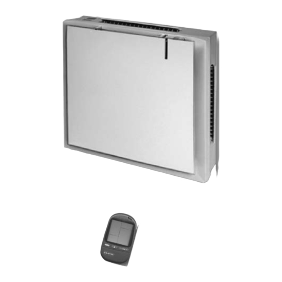
General The new TOP DCI Inverter split wall mounted range comprise the RC (heat pump) models, as follows: • TOP 25 DCI • TOP 35 DCI The indoor TOP DCI units are available as LED display types, featuring esthetic design, compact dimensions, and low noise operation. - Page 5 INTRODUCTION • Coil with treated aluminum fins. • Motorized flaps. • Multi-speed motor with internal protection. • DC motor with internal protection. • Advanced electronic control box assembly. • Interconnecting wiring terminal block. • Mounting plate. Filtration The TOP DCI series presents one type of air filters:. •...
-
Page 6: Inbox Documentation
Each unit is supplied with its own installation, operation and remote control manuals. 1.10 Matching Table 1.10.1 R410A INDOOR UNITS OUTDOOR UNITS MODEL REFRIGER. TOP 25 TOP 35 DCI 25 R410A √ DCI 35 R410A √ SM TOPDCI 1-E.1 GB... -
Page 7: Product Data Sheet
PRODUCT DATA SHEET PRODUCT DATA SHEET TOP 25 DCI Model Indoor Unit TOP 25 DCI Model Outdoor Unit DCI 25 R410A Installation Method of Pipe Flared Characteristics Units Cooling Heating Btu/hr 8530(4780-11600) 8530(5120-15360) Capacity 2.5(1.4-3.4) 2.5(1.5-4.5) 0.658(0.45-0.98) 0.625(0.48-1.53) Power input... - Page 8 PRODUCT DATA SHEET TOP 35 DCI Model Indoor Unit TOP 35 DCI Model Outdoor Unit DCI 35 R410A Installation Method of Pipe Flared Characteristics Units Cooling Heating Btu/hr 11940(4780-14000) 11940(5120-19100) Capacity 3.5(1.4-4.1) 3.5(1.5-5.6) 1.09(0.5-1.31) 0.969(0.53-1.94) Power input 3.21 3.61 EER (Cooling) or COP(Heating) Energy efficiency class 220-240 Power supply...
-
Page 9: Rating Conditions
RATING CONDITIONS RATING CONDITIONS Standard conditions in accordance with ISO 5151, ISO 13253 (for ducted units) and EN 14511. Cooling: Indoor: C DB 19 C WB Outdoor: 35 C DB Heating: Indoor: C DB Outdoor: 7 C DB 6 C WB Operating Limits 3.1.1 R410A... -
Page 10: Outline Dimensions
OUTLINE DIMENSIONS OUTLINE DIMENSIONS Indoor Unit: TOP 25 DCI, TOP 35 DCI Outdoor Unit: DCI 25, DCI 35 SM TOPDCI 1-E.1 GB CONTENTS... -
Page 11: Performance Data & Pressure Curves
PERFORMANCE DATA & PRESSURE CURVES PERFORMANCE DATA & PRESSURE CURVES TOP 25 DCI / DCI 25 R410A 5.1.1 Cooling Mode at 7.5m Tubing Connection. 230V : Indoor Fan at High Speed. Entering Air WB/DB ID Coil( Entering Air DB Data... - Page 12 PERFORMANCE DATA & PRESSURE CURVES 5.1.2 Heating Mode at 7.5m Tubing Connection. 230V : Indoor Fan at High Speed. ENTERING AIR DB ID COIL( ENTERING WB OD COIL( 1.32 0.53 1.27 0.56 1.22 0.59 1.42 0.54 1.37 0.57 1.32 0.60 1.51 0.55 1.46...
- Page 13 PERFORMANCE DATA & PRESSURE CURVES Pressure Curves. 5.3.1 Cooling. Suction Pressure VS.Outdoor Temp 14.0 15/21(WB/DB ºC) 13.0 17/24(WB/DB ºC) 19/27(WB/DB ºC) 12.0 21/29(WB/DB ºC) 11.0 23/32(WB/DB ºC) 10.0 Outdoor Temp.(DB Discharge Pressure VS.Outdoor Temp 15/21(WB/DB ºC) 17/24(WB/DB ºC) 19/27(WB/DB ºC) 21/29(WB/DB ºC) 23/32(WB/DB ºC) Outdoor Temp.(DB...
- Page 14 PERFORMANCE DATA & PRESSURE CURVES 5.3.2 Heating. Suction Pressure VS.Outdoor Temp 12.0 11.0 10.0 15 DB (ºC) 20 DB (ºC) 25 DB (ºC) Outdoor Temp.( WB Discharge Pressure VS.Outdoor Temp 25 DB (ºC) 20 DB (ºC) 15 DB (ºC) Outdoor Temp.( WB SM TOPDCI 1-E.1 GB CONTENTS...
- Page 15 PERFORMANCE DATA & PRESSURE CURVES TOP 35 DCI / DCI 35 R410A 5.4.1 Cooling Mode at 7.5m Tubing Connection. 230V : Indoor Fan at High Speed. Entering Air WB/DB ID Coil( Entering Air DB Data OD Coil( 15/21 17/24 19/27 21/29 23/32 3.43...
- Page 16 PERFORMANCE DATA & PRESSURE CURVES 5.4.2 Heating Mode at 7.5m Tubing Connection. 230V : Indoor Fan at High Speed. ENTERING AIR DB ID COIL( ENTERING WB OD COIL( 1.75 0.76 1.69 0.81 1.62 0.85 1.89 0.78 1.82 0.82 1.75 0.87 2.00 0.79 1.94...
- Page 17 PERFORMANCE DATA & PRESSURE CURVES Pressure Curves. 5.6.1 Cooling. Suction Pressure VS.Outdoor Temp 14.0 15/21(WB/DB ºC) 13.0 17/24(WB/DB ºC) 19/27(WB/DB ºC) 12.0 21/29(WB/DB ºC) 11.0 23/32(WB/DB ºC) 10.0 Outdoor Temp.(DB Discharge Pressure VS.Outdoor Temp 15/21(WB/DB ºC) 17/24(WB/DB ºC) 19/27(WB/DB ºC) 21/29(WB/DB ºC) 23/32(WB/DB ºC) Outdoor Temp.(DB...
- Page 18 PERFORMANCE DATA & PRESSURE CURVES 5.6.2 Heating. Suction Pressure VS.Outdoor Temp 11.0 10.0 15 DB (ºC) 20 DB (ºC) 25 DB (ºC) Outdoor Temp.( WB Discharge Pressure VS.Outdoor Temp 25 DB (ºC) 20 DB (ºC) 15 DB (ºC) Outdoor Temp.( WB SM TOPDCI 1-E.1 GB CONTENTS...
-
Page 19: Sound Level Characteristics
SOUND LEVEL CHARACTERISTICS SOUND LEVEL CHARACTERISTICS Sound Pressure Level Unit Wall Mic. Figure 1 Sound Pressure Level Spectrum (Measured as Figure 1) TOP 25 DCI TOP 35 DCI -70NC -70NC -60NC -60NC -50NC -50NC -40NC -40NC -30NC -30NC APPROXIMATE APPROXIMATE... - Page 20 SOUND LEVEL CHARACTERISTICS Outdoor units Unit Mic. Ground Figure 2 Sound Pressure Level Spectrum (Measured as Figure 2) DCI 25 Cooling DCI 25 Heating DCI 35 Cooling DCI 35 Heating SM TOPDCI 1-E.1 GB CONTENTS...
-
Page 21: Electrical Data
ELECTRICAL DATA ELECTRICAL DATA Single Units MODEL TOP 25 DCI TOP 35 DCI To indoor To indoor Power Supply 1PH-230V-50Hz 1PH-230V-50Hz 10.0 10.0 Max Current, (A) 15.0 15.0 Circuit Breaker,(A) Power Supply Wiring. 3 x 1.5 mm 3 x 1.5 mm (No. -
Page 22: Wiring Diagrams
WIRING DIAGRAMS WIRING DIAGRAMS Units: TOP 25 DCI, TOP 35 DCI / DCI 25, DCI 35 R410A POWER SUPPLY SM TOPDCI 1-E.1 GB CONTENTS... -
Page 23: Electrical Connections
ELECTRICAL CONNECTIONS ELECTRICAL CONNECTIONS TOP 25 / DCI 25, TOP 35 / DCI 35 R410A Indoor unit Outdoor unit SM TOPDCI 1-E.1 GB CONTENTS... -
Page 24: Refrigeration Diagrams
REFRIGERATION DIAGRAMS REFRIGERATION DIAGRAMS 10.1 Heat Pump Models 10.1.1 TOP 25 DCI, TOP 35 DCI R410A 10.1.1a Cooling Mode OUTDOOR UNIT INDOOR UNIT Sensor Sensor Flared Valves connection Reverse valve Indoor coil Strainer Strainer Outdoor coil 10.1.1b Heating Mode OUTDOOR UNIT... -
Page 25: Tubing Connections
TUBING CONNECTIONS TUBING CONNECTIONS TUBE (Inch) ¼” ⅜” ½” ⅝” ¾” TORQUE (Nm) Flare Nuts 11-13 40-45 60-65 70-75 80-85 Valve Cap 13-20 13-20 18-25 18-25 40-50 Service Port Cap 11-13 11-13 11-13 11-13 11-13 Valve Protection Cap-end Refrigerant Valve Port (use Allen wrench to open/close) Valve Protection Cap Refrigerant Valve Service Port Cap... -
Page 26: Control System
CONTROL SYSTEM CONTROL SYSTEM 12.1 General Functions and Operating RulesThe DCI software parametric. All the model dependent parameters are shown in Blue color and with Italic style [parameter]. The parameters values are given in the last section of this control logic chapter of the service manual. - Page 27 CONTROL SYSTEM NLOAD Target Frequency Maximum Frequency 10<NLOAD<127 Interpolated value between minimum and maximum frequency Minimum frequency Compressor is stopped Target frequency limits as a function of outdoor air temperature (OAT): OAT Range Cooling Mode limits Heating Mode limits OAT < 6 No limit 6 ≤...
-
Page 28: Outdoor Fan Control
CONTROL SYSTEM Turbo Speed The Turbo speed is activated during the first 30 minutes of unit operation when auto fan speed is selected and under the following conditions: Difference between set point and actual room temperature is bigger than 3 degrees. Room temperature >... - Page 29 CONTROL SYSTEM When compressor is switched to OFF and the heat sink temperature is above 55 degrees, the outdoor fan will remain ON in low speed for up to 3 minutes. EEV (Electronic Expansion Vavle) Control EEV Control for DCI25/35 EEV opening is defined as EEV = EEV + EEV is the initial EEV opening as a function of the compressor frequency, operation mode, unit...
- Page 30 CONTROL SYSTEM Heat Mode NLOAD is calculated according to the difference between actual room temperature and user set point temperature by fuzzy control. In high/ medium/ low indoor fan user setting, unit will operate fan in selected speed. In AutoFan user setting, fan speed will be adjusted automatically according to the calculated NLOAD.
- Page 31 CONTROL SYSTEM Dry Mode As long as room temperature is higher then the set point, indoor fan will work in low speed and compressor will work between 0 and MaxNLOADIF1C Hz. When the room temperature is lower than the set point, compressor will be switched OFF and indoor fan will cycle 3 minutes OFF, 1 minute ON.
- Page 32 CONTROL SYSTEM Stop-Compressor Normal Control Status Compressor Temperature Increases Else Normal Stop Rise HzDown 1 Stop Rise HzDown 2 HzDown 1 Stop Compressor Stop Compressor Compressor Over Current Protection Only For DCI 25 / 35 Stop-Compresor CCROC4 HzDown2 CCROC3 HzDown1 CCROC2 Stop-Rise CCROC1...
- Page 33 CONTROL SYSTEM Heat Sink Overheating Protection Heat Sink Overheating Protection For DCI 25 / 35 HST Trend Fast Decreasing Decreasing No Change Increasing Fast Increasing ≥ 90 [85, 90) [82, 85) [80, 82) Norm Norm Norm [78 , 80) < 78 Norm Outdoor Coil Deicing Protection Outdoor coil Deicing Protection For DCI 25 / 35...
- Page 34 CONTROL SYSTEM ● Deicing Operation Procedure O C T T h re s h o ld C O M P D e ic e F re q C h R V m a x. 1 2 m in u te s H E A T C O O L O F A N...
- Page 35 CONTROL SYSTEM STAND BY Lights up when the Air Conditioner is connected to power and INDICATION ready to receive the R/C commands STBY will be indicately by the following illumination (purple color): Duty Cycle (%) ‘Unit Mode’ Heat (Red) ‘Unit Mode’ Cool (Blue) The combined color is purple (it’s not red and not blue) OPERATION INDICATION ‘Unit Mode’...
- Page 36 CONTROL SYSTEM Presence detector Remote controller ICOM-X command Mode Button ESF/INOIZER INDICATOR Lights up during ESF/ ionizer operation. TIMER INDICATOR Lights up during Timer and Sleep operation. FILTER INDICATOR The filer LED never lights up(even when the filer needs to be cleaned).
-
Page 37: Dip Switch Settings
CONTROL SYSTEM Self Test Jumper(J1) Jumper for production line check. DIP Switch Settings ● Compensation setting This setting activates the compensation to the return air temperature in heating mode. For indoor unit like cassette, the DIP switch J2 should be ON. Compensation J2(DIP1) Activated (factory setting)-... - Page 38 CONTROL SYSTEM The indoor alarm outputs are defined according to the following table: Problem ICT is disconnected ICT is shorted RAT is disconnected RAT is shorted Reserved (for MSMP used as RGT fault) ICTE shorted/disconnected (when enabled) Undefined IDU family/model No Communication No Encoder Reserved...
- Page 39 CONTROL SYSTEM The outdoor alarm outputs are defined in the following way: Problem OCT is disconnected OCT is shorted CTT is disconnected CTT is shorted HST is disconnected (when enabled) HST is shorted (when enabled) OAT is disconnected (when enabled) OAT is shorted (when enabled) TSUC is disconnected (when enabled) TSUC is shorted (when enabled)
-
Page 40: Unit Setting
CONTROL SYSTEM Test Mode Entering Test Mode System can enter Test mode in two ways: Automatically when the following conditions exists for 30 minutes continuously: Mode = Cool, Set point = 16, Room temperature = 27(+1/-2), Outdoor temperature = 35(+2/-1) Or Mode = Heat, Set point = 30, Room temperature = 20±1, Outdoor temperature = 7±(+1/-2) Manually when entering diagnostics with the following settings: Mode = Cool, Set point = 16... - Page 41 CONTROL SYSTEM SW Parameters Indoor Units SW Parameters Model dependent parameters TOP DCI Family A (TOP 25 DCI) B (TOP 35 DCI) (Reserved) (Reserved) IFVLOWC IFLOWC IFMEDC IFHIGHC IFTURBOC IFVLOWH IFLOWH IFMEDH IFHIGHH IFTURBOH Cap .Group NomLoadC NomLoadH MaxNLOADIF1C MaxNLOADIF2C...
- Page 42 CONTROL SYSTEM Outdoor Units SW Parameters Model dependent parameters forDCI25/DCI35 Name A Single DCI-25 B Single DCI-35 MinFreqC MaxFreqC MaxFreqCRunPhase MinFreqH MaxFreqH MaxFreqHRunPhase LoadDeadZoneC LoadDeadZoneH NormAccel NormDecel Step1Freq Step2Freq Step3Freq OFVL OFLOWC OFMEDC OFMAXC OFLOWH OFMEDH OFMAXH OFANTESTMODEC OFANTESTMODEH OFDelTestMode CTTOH1 CTTOH2 CTTOH3...
-
Page 43: Troubleshooting
TROUBLESHOOTING TROUBLESHOOTING 13.1 Models: TOP 25 / DCI 25, TOP 35 / DCI 35 ELECTRICAL & CONTROL TROUBLESHOOTING ATTENTION: check for broken or loose cable lugs first. Problem Cause Remedy Unit does not operate. Unit not connected to power Plug in the power cord... - Page 44 EXPLODED VIEWS AND SPARE PARTS LISTS EXPLODED VIEWS AND SPARE PARTS LISTS 14.1 R410A 14.1.1 Indoor Unit: TOP 25 DCI, TOP 35 DCI 21,27 14-1 SM TOPDCI 1-E.1 GB CONTENTS...
-
Page 45: Exploded Views And Spare Parts Lists
EXPLODED VIEWS AND SPARE PARTS LISTS 14.1.2 Indoor Unit: TOP 25 DCI Description Quan. 465720088 Front Panel Assy. (Electra) 465720090 Front Panel Assy. (Airwell) 465720091 Front Panel Assy./silver (Electra) 465720092 Front Panel Assy. /silver(Airwell) 465720162 Front Panel Assy. /silver(Johnson) 465720099 Front Panel Assy. - Page 46 EXPLODED VIEWS AND SPARE PARTS LISTS 14.1.3 Indoor Unit: TOP 35 DCI Description Quan. 465720088 Front Panel Assy. (Electra) 465720090 Front Panel Assy. (Airwell) 465720091 Front Panel Assy. (Electra) 465720092 Front Panel Assy. (Airwell) 465720162 Front Panel Assy. /silver(Johnson) 465720099 Front Panel Assy.
- Page 47 EXPLODED VIEWS AND SPARE PARTS LISTS 14.1.4 Outdoor Unit DCI 25, DCI 35 R410A 14-4 SM TOPDCI 1-E.1 GB CONTENTS...
- Page 48 EXPLODED VIEWS AND SPARE PARTS LISTS 14.1.5 Outdoor Unit DCI 25, DCI 35 R410A Part No. Description 433218 A Front Panel A 4526340 Air inlet ring-420 4523060 Base Painting Assy. 4526299 Partition 4519300 Nut M5 L 463300505 Standard Valve Connect Pipe/Gas Valve/ TP2M 9.53*0.8/CON GCN ONG3 461010004 Gas Valve 3/8"...
- Page 49 APPENDIX A APPENDIX A INSTALLATION AND OPERATION MANUAL ► OPERATION MANUAL TOP 25 / DCI 25, TOP 35 / DCI 35 ► INSTALLATION MANUAL TOP 25 / DCI 25, TOP 35 / DCI 35 15-1 SM TOPDCI 1-E.1 GB CONTENTS...
Need help?
Do you have a question about the TOP 25 and is the answer not in the manual?
Questions and answers