
Related Manuals for Electra FS 1200


Summary of Contents for Electra FS 1200
- Page 1 Technical Service Manual SERIES: FS KFR120L Free Standing REFRIGERANT R407C HEAT PUMP Rev.: Date: 29/02/04 Series: FS Date: 20/02/2004 ELECTRA CONSUMER PRODUCTS LTD Rev.: 01...
- Page 2 Condensate drain tube I.D liquid Tube size O.D suction Indoor-Outdoor Connection between units height difference MAX. 20m MAX. 40m tubing length Operation control type Operation by hand on LCD Heating elements Ducts Others Series: FS Date: 20/02/2004 ELECTRA CONSUMER PRODUCTS LTD Rev.: 01...
- Page 3 Upper limit 27°C DB 24°C DB, 18°C WB Heating Lower limit 20°C DB -9°C DB, -10°C WB 1 PH 198 – 242 V Voltage 3 PH 360 – 440 V Series: FS Date: 20/02/2004 ELECTRA CONSUMER PRODUCTS LTD Rev.: 01...
- Page 4 FS KFR 120L /OU10-50 R407C Series: FS Date: 20/02/2004 ELECTRA CONSUMER PRODUCTS LTD Rev.: 01...
- Page 5 Outdoor Tem p. (C DB) FS1200T R407c HEATING CAPACITY 21,000 18,500 16,000 13,500 Indoor Temp. 11,000 20 C DB 8,500 18 C DB 15 C DB 6,000 Outdoor Tem p. (C DB) Series: FS Date: 20/02/2004 ELECTRA CONSUMER PRODUCTS LTD Rev.: 01...
- Page 6 FS1200T R407c HEATING TOTAL INPUT 6,500 6,000 5,500 5,000 4,500 4,000 Indoor Temp. 3,500 20 C DB 18 C DB 3,000 15 C DB 2,500 Outdoor Tem p. (C DB) Series: FS Date: 20/02/2004 ELECTRA CONSUMER PRODUCTS LTD Rev.: 01...
- Page 7 Outdoor Tem p. (C DB) FS1200T R407c HEATING SUCTION PRESSURE 5.00 4.50 4.00 3.50 3.00 Indoor Temp. 2.50 20 C DB 2.00 18 C DB 15 C DB 1.50 Outdoor Tem p. (C DB) Series: FS Date: 20/02/2004 ELECTRA CONSUMER PRODUCTS LTD Rev.: 01...
- Page 8 26 C DB/50%RH 23 C DB/50%RH Outdoor Tem p. (C DB) FS1200T R407cHEATING DISCHARGE PRESSURE Indoor Temp. 20 C DB 18 C DB 15 C DB Outdoor Tem p. (C DB) Series: FS Date: 20/02/2004 ELECTRA CONSUMER PRODUCTS LTD Rev.: 01...
- Page 9 FS KFR 120L Model: Series: FS Date: 20/02/2004 ELECTRA CONSUMER PRODUCTS LTD Rev.: 01...
- Page 10 HEAT PUMP MODELS SERIES: FS KFR 120L Series: FS Date: 20/02/2004 ELECTRA CONSUMER PRODUCTS LTD Rev.: 01...
-
Page 11: Tubing Connections
When the outdoor unit is installed above the indoor unit an oil trap is required every 5m along the suction line at the lowest point of the riser. In case the indoor unit is installed above the outdoor no trap is required. Outdoor Outdoor Indoor Series: FS Date: 20/02/2004 ELECTRA CONSUMER PRODUCTS LTD Rev.: 01... - Page 12 Series: FS Date: 20/02/2004 ELECTRA CONSUMER PRODUCTS LTD Rev.: 01...
- Page 13 Free Standing Air Conditioner Operation Instructions & Installation Manual...
-
Page 14: Table Of Contents
Operation Instructions Page Introduction System Description Operation Modes, Functions and Features If your air conditioner is for Indicator Lights of the Indoor Unit and Control Buttons on the Unit cooling only, please disregard the heating Operational Principal of the Unit instructions. - Page 15 Installation Instructions Page 1. Outline Dimensions for Indoor & Outdoor Unit 2. Installation Process Chart 3. Installation of Indoor Unit 3.1 Selecting Location for Indoor Unit Installation 3.2 Indoor Unit Installation 3.3 Refrigerant Line Installation 3.4 Drain Line Installation 3.5 Electrical Cable Connections 4.
-
Page 17: System Description
SYSTEM DESCRIPTION Indoor Unit Outdoor Unit Air In Air Out Air Outlet AUTO Control Panel Air Out Air Out Air Inlet Air In Drain Tube Interconnecting Lines... -
Page 18: Operation Modes, Functions And Features
OPERATION MODES, FUNCTIONS AND FEATURES This series of conditioners have the following functions: Cools, dehumidifies and filters the room air. Maintains desired room COOL temperature. Heats and filters the room air. Maintains the desired room temperature. HEAT Automatically switches from COOLING to HEATING or from HEATING to AUTO COOLING, maintaining the desired temperature according to the room conditions. - Page 19 OPERATION MODES, FUNCTIONS AND FEATURES Filter indicator on the indoor unit display is turned on when when the filter FILTER requires cleaning. After cleaning and reinstalling the filter. The system INDICATOR should be reset. 3-MIN. The compressor is protected by a three-minute delayed restart. DELAYED RNU The microprocessor retains the last data entry whether or not the unit is plugged in.
-
Page 20: Buttons On The Unit
INDICATOR LIGHTS AND CONTROL BUTTONS ON THE UNIT A. Stand-by Indicator Lights up when the air conditioner is connected to power. B. Fan Speed Button: To select Low Fan / Mid Fan / High Fan / Auto Fan. Four modes for option C. -
Page 21: Operational Principal Of The Unit
OPERATIONAL PRINCIPLE OF THE UNIT HEATING MODE OUTDOOR UNIT Suction accumulator Service INDOOR UNIT port Indoor coil Senssor Senssor Flared Valves connection Main Capilary Reverse tube valve Capilary tube Strainer Outdoor coil Strainer Strainer Check valve Operational Principle Chart for Free Standing Room Air Conditioner with Heat Pump Both outdoor unit and indoor unit start operation after connected to power. -
Page 22: Operation Procedure (Operations On The Unit)
OPERATION PROCEDURE (Operations on the Unit) IONIZER POWER RUN FILTER TIMER RESET AUTO FAN SPEED TEMP ON/OFF TIMER CLEAR MODE SWING SLEEP LOCK Turning on the Air Conditioner 1. Connect the unit to the power supply, indicator A lights up, indicating that the unit is ready for operation. 2. -
Page 23: Cooling Operation With Auto Fan Mode
OPERATION PROCEDURE Cooling Operation with Auto Fan Mode This operation starts with the highest airflow in order to lower the room temperature quickly. Then it will automatically switch to a lower airflow to maintain the set temperature. Heating Operation 1. Select "Heating" by pressing F (mode selection) button. 2. -
Page 24: Sleep Function
OPERATION PROCEDURE Sleep Function Press Sleep button (S) to select the Sleep function. After Sleep function is activated, air conditioner will be automatically turned off after 7 hours. If Timer function is also activated, the air conditioner will be turned on or off according to Timer setting. -
Page 25: Operation Procedure
OPERATION PROCEDURE B) Press "SET" button (L), "ON" will appear. C) Press up and down button (O) & (P) respectively to adjust start time of operation. D) Press "SET" button (L) again to activate timing start function, "OFF" will appear at the same time. E) Repeat step (c) to set the closedown time. -
Page 26: Air Direction Control
OPERATION PROCEDURE Air Direction Control Automatic Vertical Air Swing Press button (R) to activate the auto air swing function. Press button (R) again to cancel the function. Turning Off Press ON/OFF button (N) to turn off the air conditioner. Indicator (V) on the air conditioner will be turned off. Indicator (A) may stay lit, indicating that the air conditioner is in stand-by mode. -
Page 27: Protection Modes And Instructions For Service Electric Heater
PROTECTION MODES AND INSTRUCTIONS FOR SERVICE ELECTRIC HEATER This series of conditioners include a great variety of automatic protection modes, some of the protection modes are listed below: Mode Operation Conditions Protection from Controlled remedy Low outdoor Evaporator Cooling and Stops outdoor fan and compressor when temperature freezing up... -
Page 28: Maintenance And Care
MAINTENANCE AND CARE Cleaning the Air Conditioner Cleaning Air Filter 1. Cut power off before cleaning. Whether or not to clean the air filter depends on the For the sake of safety, the unit must be turned instruction of the filter indicator. off and disconnected from power supply before Steps of removing the filter cleaning the equipment to avoid electricity... -
Page 29: Operating Tips
OPERATING TIPS Set a suitable room temperature; excessively low room temperature is not good for your health and wastes electricity. Avoid frequent setting of the temperature. During cooling, avoid direct sun into the room and keep curtains closed. Close doors and windows to keep the cool air in the room. -
Page 30: Preventive Measures
PREVENTIVE MEASURES Do not block up or plug up inlets or outlets of air conditioner. Do not put any obstacles in the outlets of indoor unit or outdoor unit. Do not splash water on air conditioner. There may have "buzz" when air conditioner is in operation or just turned off, which is produced by... - Page 31 PREVENTIVE MEASURES Avoid inserting sticks and other objects into suction entrance and blowing outlet. Accident may occur when touching rotating fan or electrical parts. During operation, please do not open inlet grid of indoor unit. inlet grid can only be opened after making sure the air conditioner is turned off.
-
Page 32: Before Calling For Service
BEFORE CALLING FOR SERVICE Before calling for service, please check the following malfunctions and correct it as needed. Problem Cause Remedy Unit does not operate. Unit not connected to power Insert the plug to power supply. Operation indicator does not light up. Power failure Check main fuse. -
Page 33: Outline Dimensions For Indoor & Outdoor Unit
INSTALLATION MANUAL 1. Outline dimensions for indoor & outdoor unit OUTLINE DIMENSIONS FS 1200 INDOOR UNIT FC 1200 AUTO OUTDOOR UNIT OU 10 RC... -
Page 34: Installation Process Chart
INSTALLATION MANUAL 2. Installation Process Chart 1. Installation Process Chart for Indoor Unit Selecting Location Installation of Installation of for Installation indoor unit Refrigerant Lines Installation of Drain Line Electrical Connections 2. Installation Process Chart for Outdoor Unit Selecting Location Installation of Installation of for Installation... -
Page 35: Selecting Location For Indoor Unit Installation
INSTALLATION MANUAL 3.1 Selecting Location for Indoor Unit Installation To be located at a place that the air blown-out can reach all room corners. Avoid location that could be influenced by outdoor air. Avoid location with obstructions interfering free flow of air blowing out and air intake. Avoid places with oily mist and vapors. -
Page 36: Indoor Unit Installation
INSTALLATION MANUAL 3.2 Indoor Unit Installation 1.Measures preventing dumping "Wall mounting iron piece against dumping is necessary to prevent dumping" As the unit is slim and tall, for safe caution, please proceed immediately measures preventing dumping after installation location for the unit is confirmed. Example of measures preventing dumping Wall mounting iron When wall and floor are not made by materials except for... -
Page 37: Installation Manual
INSTALLATION MANUAL 3.2 Indoor Unit Installation 2.Setting clamp preventing dumping for wall mounting According to the location of cordon in the wall ( height calculated from the floor ), select suitable method from the following figures. Cordons are not applicable when wall is floored with light steel base, please mount the clamp on supporting or one of pillars. -
Page 38: Indoor Unit
INSTALLATION MANUAL 3.3/3.4Installation of Refrigerant Lines & Drain Line Thermal insulation treatment is required on refrigerant lines and drain line to prevent condensation as both lines have dews to drip down. When using pipes purchased from market as refrigerant lines, please wrap and tighten the liquid line and the suction line with thermal insulation materials purchased in the market (thickness of heat resistance insulation material is over 12mm). - Page 39 INSTALLATION MANUAL 3.3/3.4Installation of Refrigerant Lines & Drain Line 2.Operation on Tubing Connection 1) Remove 1 screw from handle of inlet grid, pull out to Pipe protection cover your own direction and take inlet grid out. (As the inlet grid, underside of inlet grid, is embedded in the bottom base, please pull upward and take it out.) 2) Take down tap bolt (1) for securing pipe protection...
- Page 40 INSTALLATION MANUAL 3.3/3.4Installation of Refrigerant Lines & Drain Line 4. Installation of Refrigerant Lines (indoor unit) Thermal insulation on interconnecting areas Please use reliable thermal insulation on the areas, do not let flare connection and where refrigerant lines come out. (Condensing frost may produce and drip down without proceeding thermal insulation on interconnecting areas.) Please locate thermal insulation material...
-
Page 41: Electrical Cable Connections
INSTALLATION MANUAL 3.5Electrical Cable Connections Power supply connections cannot be proceeded on sub-circuit. Electrical configuration shall be based on suitable technical standard. Electrical connections must be proceeded strictly according to diagram. Bolts shall be tightened securely to avoid tear-off. Interconnecting wires between indoor and outdoor unit and power lines are not touchable mutually outside the unit. - Page 42 INSTALLATION MANUAL 3.5Electrical Cable Connections 2.Interconnecting Cable between Indoor and Outdoor Unit Wiring Method of Indoor Unit Dismantle bolts on electrical case cover and display electrical case cover. Bolts Interconnect wires as per figure below and secure with fixation clamp. Electrical case cover Comb Suction tube...
- Page 43 INSTALLATION MANUAL 4.1 Selecting Installation Location for Outdoor Unit Avoid directing sunlight. When sunlight is inevitable, please install shelter from sun to prevent direct sunlight. Noises from the unit will not influence neighbors. Location easier for interconnecting power and tubing with indoor unit. Installation should not be located at a place that flammable gas may be produced, flow in, stop and leak.
- Page 44 INSTALLATION MANUAL 4.1 Selecting Installation Location for Outdoor Unit 2.Interrelations when installing more than one unit at one place (1) When in horizontal continuous centralized Installation Please dismantle bolts on lateral protection cover of tubing. Min. 10 Maximum 10 units Min.
-
Page 45: Outdoor Unit Installation
INSTALLATION MANUAL 4.2 Outdoor Unit Installation Try your best to deliver the unit in original package to the installation location. Please be care not to overturn the unit when lifting up the unit with sling, as the gravity of the unit is not in the center. - Page 46 INSTALLATION MANUAL 4.3Interconnection and Leak Detection of Refrigerant Lines Please refer to Construction Work of Refrigerant Lines for torque requested to tighten nuts. Connection of Tubing on Indoor Unit Open up push-out hole for tubing at the bottom according to the location of indoor unit, get the connection tube across the hole and connected with tube joint on the indoor unit (Upper Right Figure).
- Page 47 INSTALLATION MANUAL 4.4 System Evacuating B. Evacuation using self-provide cooling Length of Evacuation Method Charging quantity agent of the installing worker Connection Tube of refrigerant 1. Joint the self-provide refrigerant pot to the E v a c u a t i o n w i t h nozzle of the low-pressure valve.
-
Page 48: Outdoor Unit Installation
INSTALLATION MANUAL 4.5Electrical Layout & Wiring Method Electrical wiring varies as per models. Please refer to electrical wiring diagram for details when proceeding electrical operation. (Example) Power supply Main Power Switch / Fuse (Purchased locally) Power line for indoor and outdoor unit Indoor Unit Power line of indoor and... - Page 49 INSTALLATION MANUAL 4.5Electrical Layout & Wiring Method Dismantle front lateral board Open up outdoor wire-cross hole and put on square wire-cross diagram. Induce connection wire out from 6 bit wiring board on outdoor unit, drill through outdoor wire-cross hole and indoor wire-cross hole, and connect the wire to the 6 bit wiring board on indoor unit. Please refer to the following diagram for power line wiring.
-
Page 50: Test Operation
INSTALLATION MANUAL 4.6Test Operation Cooling or Heating Test Operation To be set in Cooling mode Proceed Cooling or Heating test operation after completing leak detection on leakage. Set the Cooling or Heating mode. Refer to the instruction for the procedure. Note: the compressor has 3-min delay protection function to prevemt damage to the compressor when freguently... - Page 51 INSTALLATION MANUAL 4.7Draining Condensing Water Out of Outdoor Unit THIS FUNCTION IS ONLY APPLICABLE FOR HEAT PUMP UNIT When in heating mode, condensing water formed on outdoor unit and defrost water produced when defrost can be drained out to the suitable place through drain line. Base plate on Installation method: Insert the outdoor drain coupling into the outdoor unit...
- Page 52 MOTOR 2 MOTOR 1 COMPRESSOR CAP 2 CAP 1 CONNEC. CONNEC. FOR HEAT- CABLE CABLE PUMPONLY. HEAT FH CONTACTES IMPRTANT 3PH RELAY EBFOR CONNECTING THE FH CUT THE WIRE BETWEEN 2 TABs F.S.C OPTIONAL L3 L2 COMP R/V POWER SUPPLY:(BYINSTALLER) 3PH ~ 400V 50Hz OCT OUT 5x2.5...
- Page 53 Part No:452809000/01...
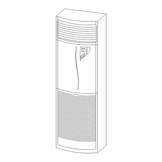
- Page 54 Model: FS KFR 120L Indoor Unit Series: FS Date: 20/02/2004 ELECTRA CONSUMER PRODUCTS LTD Rev.: 01...
- Page 55 45 7880 support plate of drain pan 45 7905 ionizer assy. 45 7879 top cover paint assy. 45 3769 swing motor 45 4539 swing bar 45 7795 swing motor bracket Series: FS Date: 20/02/2004 ELECTRA CONSUMER PRODUCTS LTD Rev.: 01...
- Page 56 FS KFR 120L Outdoor Unit Model: Series: FS Date: 20/02/2004 ELECTRA CONSUMER PRODUCTS LTD Rev.: 01...
- Page 57 FS KFR 120L Outdoor Unit Model: Rev.: 01 Series: FS Date: 20/02/2004 ELECTRA CONSUMER PRODUCTS LTD...
- Page 58 FS KFR 120L Outdoor Unit Model: Series: FS Date: 20/02/2004 ELECTRA CONSUMER PRODUCTS LTD Rev.: 01...
- Page 59 435545 COMPRESSOR WIRING WTH PLUG L1100 3PH 439661 CONES OU10 402189 SUCTION ACCUMULATOR 5" x 3/4" 7Lb 439795 BOARD 3PH PROTECTOR 436352 RAISING HANDLE OU10 190442 HEATER CRANKCASE OU10 LG Series: FS Date: 20/02/2004 ELECTRA CONSUMER PRODUCTS LTD Rev.: 01...
Need help?
Do you have a question about the FS 1200 and is the answer not in the manual?
Questions and answers