
Subscribe to Our Youtube Channel
Related Manuals for Electra PXD DCI Series


Summary of Contents for Electra PXD DCI Series
-
Page 1: Table Of Contents
PXD DCI Series Indoor Units Outdoor Units PXD 25 DCI DCI 25 PXD 35 DCI DCI 35 PXD 50 DCI DCI 50 PXD 60 DCI DCI 60 DCI 72 PXD 72 DCI DCI 72Z PXD 80 DCI DCI 80 REFRIGERANT... - Page 2 LIST OF EFFECTIVE PAGES LIST OF EFFECTIVE PAGES Note: Changes in the pages are indicated by a “Revision#” in the footer of each effected page (when none indicates no changes in the relevant page). All pages in the following list represent effected/ non effected pages divided by chapters.
- Page 3 TABLE OF CONTENTS Table of Contents INTRODUCTION ....................1-1 PRODUCT DATA SHEET ..................2-1 RATING CONDITIONS ..................3-1 OUTLINE DIMENSIONS ..................4-1 PERFORMANCE DATA & PRESSURE CURVES ..........5-1 SOUND LEVEL CHARACTERISTICS ..............6-1 ELECTRICAL DATA ....................7-1 WIRING DIAGRAMS .....................8-1 REFRIGERATION DIAGRAMS ................9-1 10. TUBING CONNECTIONS ..................10-1 11.
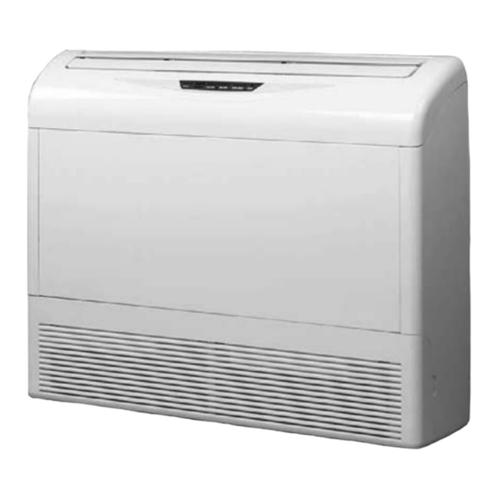
- Page 4 INTRODUCTION INTRODUCTION General The PXD split ceiling mounted range comprise RC (heat pump) models, as follows: PXD 25 ● PXD 35 ● PXD 50 ● PXD 60 ● PXD 72 ● PXD 80 ● Main Features The PXD series benefits from the most advanced technological innovations, namely: DC Inverter Technology R410A models.
- Page 5 INTRODUCTION Control The microprocessor indoor controller, and an infrared remote control, supplied as standard, providing complete operating function and programming. For further details please refer to the Operation Manual, Appendix A. Outdoor Unit The PXD outdoor units can be installed as floor or wall mounted units by using a wall supporting bracket.
- Page 6 INTRODUCTION 1.10 Matching Table 1.10.1 R410A INDOOR UNITS OUTDOOR UNITS MODEL REFRIGER. PXD 25 PXD 35 PXD 50 PXD 60 PXD 72 PXD 80 √ √ √ DCI25/35/50 R410A √ DCI 60 R410A DCI 72 √ R410A DCI 72Z √ DCI 80 R410A The above table lists outdoor units and PXD DCI indoor units which can be matched together.
- Page 7 PRODUCT DATA SHEET PRODUCT DATA SHEET PXD 25 DCI R410A Model Indoor Unit PXD 25 DCI Model Outdoor Unit ONG-25 DCI Installation Method of Pipe Flared Characteristics Units Cooling Heating Btu/hr 8530(4780~12280) 10920(5120~15350) Capacity 2.5(1.4-3.6) 3.2(1.5~4.5) 0.62(0.42-1.1) 0.93(0.4~1.6) Power input 4.03 3.41 EER (Cooling) or COP(Heating)
-
Page 8: Pxd 25 Dci Dci
PRODUCT DATA SHEET PXD 35 DCI R410A Model Indoor Unit PXD 35 DCI Model Outdoor Unit ONG-DCI 35 Installation Method of Pipe Flared Characteristics Units Cooling Heating Btu/hr 11940(5120~15010) 14330(5120~17060) Capacity 3.5(1.5-4.4) 4.2(1.5~5.0) 0.98(0.46-1.3) 1.31(0.35~1.58) Power input 3.57 3.21 EER (Cooling) or COP(Heating) Energy efficiency class Power supply V/Ph/Hz... - Page 9 PRODUCT DATA SHEET PXD 50 DCI R410A Model Indoor Unit PXD 50 DCI Model Outdoor Unit ONG-DCI 50 Installation Method of Pipe Flared Characteristics Units Cooling Heating Btu/hr 17000(5120-20460) 20460(5120-24550) Capacity 5.0(1.5-6.0) 5.8(1.5~7.2) 1.65(0.5-2.1) 1.69(0.45-2.1) Power input 3.03 3.43 EER (Cooling) or COP(Heating) Energy efficiency class Power supply V/Ph/Hz...
- Page 10 PRODUCT DATA SHEET PXD 60 DCI R410A Model Indoor Unit PXD 60 DCI Model Outdoor Unit DCI 60 R410A Installation Method Floor / Ceiling Characteristics Units Cooling Heating Btu/hr 19100(5120-21490) 21480(5120-25590) Capacity 5.60(1.5-6.3) 6.30(1.8~7.5) 1.86(0.5-2.15) 1.84(0.5-2.08) Power input 3.01 3.42 EER (Cooling) or COP(Heating) Energy efficiency class Power supply...
-
Page 11: Pxd 72 Dci
PRODUCT DATA SHEET PXD 72 DCI R410A Model Indoor Unit PXD 72 DCI Model Outdoor Unit DCI 72 R410A Installation Method of Pipe Flared Characteristics Units Cooling Heating Btu/hr 23200(5120~25590) 25910(5110-30000) Capacity 6.80(1.50-7.60) 7.60(1.60~8.60) 2.25(0.50-2.68) 2.05(05~2.30) Power input 3.02 3.61 EER (Cooling) or COP(Heating) Energy efficiency class Power supply... -
Page 12: Pxd 80 Dci Dci
PRODUCT DATA SHEET PXD 80 DCI R410A Model Indoor Unit PXD 80 DCI Model Outdoor Unit DCI 80 R410A Installation Method of Pipe Flared Characteristics Units Cooling Heating Btu/hr 25570(6820-32390) 30000(5110-35800) Capacity 7.5(1.6-8.6) 8.4(1.8-9.8) 2.49(0.5-3.1) 2.46(0.5-2.8) Power input 3.01 3.41 EER (Cooling) or COP(Heating) Energy efficiency class Power supply... - Page 13 RATING CONDITIONS RATING CONDITIONS Standard conditions in accordance with ISO 5151, ISO 13253 (for ducted units) and EN 14511. Cooling: Indoor: C DB 19 C WB Outdoor: 35 C DB Heating: Indoor: C DB Outdoor: 7 C DB 6 C WB Operating Limits R410A Indoor...
- Page 14 OUTLINE DIMENSIONS OUTLINE DIMENSIONS Indoor Unit: PXD 25, 35 DCI Indoor Unit: PXD 50, 60, 72, 80 DCI Service Manual - PXD DCI Revision Y07-03 CONTENT DCI Single...
- Page 15 OUTLINE DIMENSIONS Outdoor Unit: DCI 50 Outdoor Unit: DCI 60 Revision Y07-03 Service Manual - PXD DCI CONTENT DCI Single...
- Page 16 OUTLINE DIMENSIONS Outdoor Unit: DCI 72, DCI 72Z, DCI 80 Service Manual - PXD DCI Revision Y07-03 CONTENT DCI Single...
- Page 17 PERFORMANCE DATA & PRESSURE CURVES PERFORMANCE DATA PXD25 DCI / DCI 50 5.1.1 Cooling Capacity (kW) – Run Mode 230[V] : Indoor Fan at High Speed. ID COIL ENTERING AIR DB/WB TEMPERATURE [ OU COIL ENTERING AIR DB 22/15 24/17 27/19 29/21 32/23...
- Page 18 PERFORMANCE DATA & PRESSURE CURVES 5.1.3 Heating Capacity (kW) - Run Mode 230[V] : Indoor Fan at High Speed. ID COIL ENTERING AIR DB TEMPERATURE [ OU COIL ENTERING AIR DB/WB DATA TEMPERATURE 2.04 1.89 1.75 -15/-16 0.56 0.61 0.67 2.27 2.12 1.98...
- Page 19 PERFORMANCE DATA & PRESSURE CURVES 5.1.5 Model: PXD25 DCI / DCI 50 Cooling – Test Mode Suction Pressure Vs.Outdoor Temp. 1400 Indoor 1300 DB/WB 1200 22/15 1100 24/17 1000 27/19 29/21 32/23 Outdoor DB Temperature[ºC ] Discharge Pressure Vs. Outdoor Temp. 4000 Indoor 3750...
- Page 20 PERFORMANCE DATA & PRESSURE CURVES 5.1.6 Heating – Test Mode Suction Pressure Vs.Outdoor Temp. 1300 1200 1100 1000 Outdoor WB Temperature [ºC] Discharge Pressure Vs. Outdoor Temp. 4000 3750 Indoor DB 3500 3250 3000 2750 2500 2250 2000 1750 1500 1250 1000 Outdoor WB Temperature [ºC]...
- Page 21 PERFORMANCE DATA & PRESSURE CURVES PXD35 DCI / DCI 50 5.2.1 Cooling Capacity (kW) - Run Mode 230[V] : Indoor Fan at High Speed. ID COIL ENTERING AIR DB/WB TEMPERATURE [ OU COIL ENTERING AIR DB 22/15 24/17 27/19 29/21 32/23 DATA TEMPERATURE [...
- Page 22 PERFORMANCE DATA & PRESSURE CURVES 5.2.3 Heating Capacity (kW) - Run Mode 230[V] : Indoor Fan at High Speed. ID COIL ENTERING AIR DB TEMPERATURE [ OU COIL ENTERING AIR DB/WB DATA TEMPERATURE 2.67 2.49 2.30 -15/-16 0.79 0.87 0.95 2.98 2.79 2.60...
- Page 23 PERFORMANCE DATA & PRESSURE CURVES 5.2.5 Model: PXD35 DCI / DCI 50 Cooling – Test Mode Suction Pressure VS.Outdoor Temp. 1400 Indoor DB/WB 1300 22/15 1200 24/17 1100 27/19 1000 29/21 32/23 Outdoor DB Temperature[ºC ] Discharge Pressure VS. Outdoor Temp. 4000 3750 Indoor...
- Page 24 PERFORMANCE DATA & PRESSURE CURVES 5.2.6 Heating – Test Mode Suction Pressure VS.Outdoor Temp. 1300 1200 1100 1000 Outdoor WB Temperature [ºC] Discharge Pressure VS. Outdoor Temp. 4000 3750 3500 3250 Indoor DB 3000 2750 2500 2250 2000 1750 1500 1250 1000 Outdoor WB Temperature [ºC]...
- Page 25 PERFORMANCE DATA & PRESSURE CURVES Capacity Correction Factor Due to Tubing Length 5.3.1 PXD 25/35 DCI / DCI 50 :Cooling 1.01 1.00 0.99 0.98 0.97 0.96 0.95 0.94 0.93 0.92 0.91 9 10 11 12 13 14 15 16 17 18 19 20 Tubing Length [m ] 5.3.2 Heating...
- Page 26 PERFORMANCE DATA & PRESSURE CURVES PXD50 DCI / DCI 50 5.4.1 Cooling Capacity (kW) - Run Mode 230[V] : Indoor Fan at High Speed. ID COIL ENTERING AIR DB/WB TEMPERATURE [ OU COIL ENTERING AIR DB DATA 22/15 24/17 27/19 29/21 32/23 TEMPERATURE [...
- Page 27 PERFORMANCE DATA & PRESSURE CURVES 5.4.3 Heating Capacity (kW) - Run Mode 230[V] : Indoor Fan at High Speed. ID COIL ENTERING AIR DB TEMPERATURE [ OU COIL ENTERING AIR DB/WB DATA TEMPERATURE 2.64 2.26 1.88 -15/-16 1.18 1.27 1.35 3.48 3.10 2.72...
- Page 28 PERFORMANCE DATA & PRESSURE CURVES 5.4.5 Model: PXD50 DCI / DCI 50 Cooling – Test Mode Suction Pressure VS.Outdoor Temp. 1400 Indoor 1300 DB/WB 1200 1100 22/15 24/17 1000 27/19 29/21 32/23 Outdoor DB Temperature[ºC ] Discharge Pressure VS. Outdoor Temp. 4250 4000 Indoor...
- Page 29 PERFORMANCE DATA & PRESSURE CURVES 5.4.6 Heating – Test Mode Suction Pressure VS.Outdoor Temp. 1100 1000 Outdoor WB Temperature [ºC] Discharge Pressure VS. Outdoor Temp. 4000 3750 Indoor DB 3500 3250 3000 2750 2500 2250 2000 1750 1500 1250 1000 Outdoor WB Temperature [ºC] Service Manual - PXD DCI Revision Y07-03...
- Page 30 PERFORMANCE DATA & PRESSURE CURVES Capacity Correction Factor Due to Tubing Length 5.5.1 PXD 50 DCI :Cooling 1.01 0.99 0.97 0.95 0.93 0.91 0.89 10 12 16 18 22 24 26 28 Tubing length(m ) 5.5.2 Heating 1.02 1.00 0.98 0.96 0.94 0.92...
- Page 31 PERFORMANCE DATA & PRESSURE CURVES PXD60 DCI / DCI 60 5.6.1 Cooling Capacity (kW) - Run Mode 230[V] : Indoor Fan at High Speed. ID COIL ENTERING AIR DB/WB TEMPERATURE [ OU COIL ENTERING AIR DB DATA 22/15 24/17 27/19 29/21 32/23 TEMPERATURE [...
- Page 32 PERFORMANCE DATA & PRESSURE CURVES 5.6.3 Heating Capacity (kW) - Run Mode 230[V] : Indoor Fan at High Speed. ID COIL ENTERING AIR DB TEMPERATURE [ OU COIL ENTERING AIR DB/WB DATA TEMPERATURE 2.87 2.45 2.04 -15/-16 1.29 1.38 1.47 3.78 3.37 2.96...
- Page 33 PERFORMANCE DATA & PRESSURE CURVES 5.6.5 Model: PXD60 DCI / DCI 60 Cooling – Test Mode Suction Pressure Vs.Outdoor Temp. 1100 Indoor 1050 DB/WB 1000 22/15 24/17 27/19 29/21 32/23 Outdoor DB Temperature[ Discharge Pressure Vs.Outdoor Temp. 4000 Indoor 3750 DB/WB 3500 3250...
- Page 34 PERFORMANCE DATA & PRESSURE CURVES 5.6.6 Heating – Test Mode Suction Pressure Vs.Outdoor Temp. 1200 1100 1000 Indoor DB Outdoor WB Temperature[ Discharge Pressure Vs. Outdoor Temp. 3750 3500 3250 Indoor DB 3000 2750 2500 2250 2000 1750 1500 Outdoor WB Temperature[ 5-18 Revision Y07-03 Service Manual - PXD DCI...
- Page 35 PERFORMANCE DATA & PRESSURE CURVES Capacity Correction Factor Due to Tubing Length 5.7.1 PXD60 DCI / DCI 60 :Cooling 1.02 1.00 0.98 0.96 0.94 0.92 0.90 0.88 Heating Tube Length(m) Tube Length [m] Capacity Ratio 1.00 1.00 1.00 1.00 0.970 0.910 0.844 0.782...
- Page 36 PERFORMANCE DATA & PRESSURE CURVES PXD72 DCI / DCI 72, DCI 72Z 5.8.1 Cooling Capacity (kW) - Run Mode 230[V] : Indoor Fan at High Speed. ID COIL ENTERING AIR DB/WB TEMPERATURE [ OU COIL ENTERING AIR DB DATA 22/15 24/17 27/19 29/21...
- Page 37 PERFORMANCE DATA & PRESSURE CURVES 5.8.3 Heating Capacity (kW) - Run Mode 230[V] : Indoor Fan at High Speed. ID COIL ENTERING AIR DB TEMPERATURE [ OU COIL ENTERING AIR DB/WB DATA TEMPERATURE 3.46 2.96 2.46 -15/-16 1.48 1.58 1.69 4.57 4.07 3.57...
- Page 38 PERFORMANCE DATA & PRESSURE CURVES 5.8.5 Model: PXD72 DCI / DCI 72, DCI 72Z Cooling – Test Mode Suction Pressure Vs. Outdoor Temp. 1000 Indoor DB/WB 22/15 24/17 27/19 29/21 32/23 Outdoor DB Temperature[ Discharge Pressure Vs. Temp. 3900 3700 Indoor 3500 DB/WB...
- Page 39 PERFORMANCE DATA & PRESSURE CURVES 5.8.6 Heating – Test Mode Suction Pressure Vs. Outdoor Temp. 1050 Indoor DB Outdoor WB Temperature[ Discharge Pressure Vs. Outdoor Temp. 3700 3500 3300 Indoor DB 3100 2900 2700 2500 2300 2100 1900 1700 Outdoor WB Temperature[ Service Manual - PXD DCI Revision Y07-03 5-23...
- Page 40 PERFORMANCE DATA & PRESSURE CURVES Capacity Correction Factor Due to Tubing Length 5.9.1 PXD72 DCI / DCI 72, DCI 72Z :Cooling 1.01 0.99 0.97 0.95 0.93 0.91 0.89 0.87 0.85 Heating Tube Length [m]) Tube Length(m) 5.9.2 Heating 1.05 1.00 0.95 0.90 0.85...
- Page 41 PERFORMANCE DATA & PRESSURE CURVES 5.10 PXD80 DCI / DCI 80 5.10.1 Cooling Capacity (kW) - Run Mode 230[V] : Indoor Fan at High Speed. ID COIL ENTERING AIR DB/WB TEMPERATURE [ OU COIL ENTERING AIR DB DATA 22/15 24/17 27/19 29/21 32/23...
- Page 42 PERFORMANCE DATA & PRESSURE CURVES 5.10.3 Heating Capacity (kW) - Run Mode 230[V] : Indoor Fan at High Speed. ID COIL ENTERING AIR DB TEMPERATURE [ OU COIL ENTERING AIR DB/WB DATA TEMPERATURE 3.96 3.39 2.82 -15/-16 1.78 1.91 2.04 5.23 4.66 4.09...
- Page 43 PERFORMANCE DATA & PRESSURE CURVES 5.10.5 Model: PXD80 DCI / DCI 80 Cooling – Test Mode Suction Pressure Vs. Outdoor Temp. 1000 Indoor DB/WB 22/15 24/17 27/19 29/21 32/23 Outdoor DB Temperature[ Discharge Pressure Vs.Outdoor Temp. 3900 3700 Indoor 3500 3300 DB/WB 3100...
- Page 44 PERFORMANCE DATA & PRESSURE CURVES 5.10.6 Heating – Test Mode Suction Pressure Vs.Outdoor Temp. 1150 1050 Indoor DB Outdoor WB Temperature[ Discharge Pressure Vs.Outdoor Temp. 3850 3600 3350 Indoor DB 3100 2850 2600 2350 2100 1850 1600 Outdoor WB Temperature[ 5-28 Revision Y07-03 Service Manual - PXD DCI...
- Page 45 PERFORMANCE DATA & PRESSURE CURVES 5.11 Capacity Correction Factor Due to Tubing Length 5.11.1 PXD80 DCI / DCI 80 :Cooling 1.01 1.00 0.99 0.98 0.97 0.96 0.95 0.94 0.93 0.92 Heating Tube Length(m) Tube length [m] Capacity Ratio 1.00 1.00 1.00 1.00 0.981...
- Page 46 SOUND LEVEL CHARACTERISTICS SOUND LEVEL CHARACTERISTICS Sound Pressure Level Unit Wall Mic. Ground Figure 1 Soud Pressure Level Spectrum (Measured as Figure 1) PXD 25 PXD 35 FAN SPEED LINE Service Manual - PXD DCI Revision Y07-0 CONTENT DCI Single...
- Page 47 SOUND LEVEL CHARACTERISTICS PXD 50 PXD 60 PXD 72 PXD 80 FAN SPEED LINE Revision Y07-03 Service Manual - PXD DCI CONTENT DCI Single...
- Page 48 SOUND LEVEL CHARACTERISTICS Outdoor units Unit Mic. Ground Figure 2 Sound Pressure Level Spectrum (Measured as Figure 2 DCI 25 Cooling DCI 25 Heating DCI 35 Cooling DCI 35 Heating Service Manual - PXD DCI Revision Y07-0 CONTENT DCI Single...
- Page 49 SOUND LEVEL CHARACTERISTICS DCI 50 Cooling DCI 50 Heating DCI 60 Cooling DCI 60 Heating FAN SPEED LINE Revision Y07-03 Service Manual - PXD DCI CONTENT DCI Single...
- Page 50 SOUND LEVEL CHARACTERISTICS DCI 72 Cooling DCI 72 Heating DCI 72Z Cooling DCI 72Z Heating FAN SPEED LINE Service Manual - PXD DCI Revision Y07-0 CONTENT DCI Single...
- Page 51 SOUND LEVEL CHARACTERISTICS DCI 80 Cooling DCI 80 Heating FAN SPEED LINE Revision Y07-03 Service Manual - PXD DCI CONTENT DCI Single...
- Page 52 ELECTRICAL DATA ELECTRICAL DATA Single Phase Units MODEL PXD 25 DCI PXD 35 DCI PXD 50 DCI PXD 60 DCI PXD 72 DCI PXD 80 DCI To indoor To indoor To indoor To indoor To outdoor To outdoor Power Supply 1PH-230V- 1PH-230V- 1PH-230V-...
- Page 53 WIRING DIAGRAMS WIRING DIAGRAMS PXD 25, 35, 50, 60 DCI / DCI 50, 60 Service Manual - PXD DCI Revision Y07-03 CONTENT DCI Single...
- Page 54 WIRING DIAGRAMS PXD72 DCI / DCI 72Z Revision Y07-03 Service Manual - PXD DCI CONTENT DCI Single...
- Page 55 WIRING DIAGRAMS PXD 72, 80 DCI Service Manual - PXD DCI Revision Y07-03 CONTENT DCI Single...
- Page 56 WIRING DIAGRAMS DCI 72, DCI 80 Revision Y07-03 Service Manual - PXD DCI CONTENT DCI Single...
- Page 57 REFRIGERATION DIAGRAMS REFRIGERATION DIAGRAMS PXD 25, 35, 50, 60, 72, 80 DCI Cooling Mode Heating Mode E E V Service Manual - PXD DCI Revision Y07-03 CONTENT DCI Single...
- Page 58 TUBING CONNECTIONS TUBING CONNECTIONS TUBE (Inch) ¼” ⅜” ½” ⅝” ¾” TORQUE (Nm) Flare Nuts 11-13 40-45 60-65 70-75 80-85 Valve Cap 13-20 13-20 18-25 18-25 40-50 Service Port Cap 11-13 11-13 11-13 11-13 11-13 Valve Protection Cap-end Refrigerant Valve Port (use Allen wrench to open/close) Valve Protection Cap Refrigerant Valve Service Port Cap...
- Page 59 TROUBLESHOOTING TROUBLESHOOTING 11.1 Troubleshooting for DCI50/60/72Z WARNING!!! When Power Up – the whole outdoor unit controller, including the wiring, is under HIGH VOLTAGE!!! Never open the Outdoor unit before turning off the Power!!! When turned off, the system is still charged (400V)!!! It takes about 3 Min.
- Page 60 TROUBLESHOOTING Symptom Probable Cause Corrective Action Check RV power connections, if Unit works in wrong mode Electronics or power (cool instead of heat or check RV operation with direct connection to RV heat instead of cool) 230VAC power supply, if OK, replace outdoor controller.
- Page 61 TROUBLESHOOTING 11.1.3 Judgment by Indoor/Outdoor Unit Diagnostics Enter diagnostics mode - press for five seconds Mode button in any operation mode. Acknowledgment is by 3 short beeps and lights of COOL and HEAT LED’s. Then, every short pressing of Mode button will scroll between Indoor and Outdoor unit diagnostic modes by the acknowledgment of 3 short beeps and lighting of COOL and HEAT LED’s.
- Page 62 TROUBLESHOOTING 11.1.4.1 Indoor Unit Diagnostics and Corrective Actions Fault Probable Cause Corrective Action Sensor failures of Check sensor connections or all types replace sensor Indoor and Outdoor Communication controllers are with Replace Indoor controller mismatch different versions Communication or Check Indoor to Outdoor No Communication grounding wiring is not wiring and grounding...
- Page 63 TROUBLESHOOTING Fault Probable Cause Corrective Action Check the voltage - If there is no voltage between indoor fan replace main P.C.B terminals on the main P.C.B. The outdoor fan There is voltage between - Replace capacitor or motor. does not function outdoor fan terminals on correctly.
- Page 64 TROUBLESHOOTING Fault Probable Cause Corrective Action - Overload safety device on compressor is cut - Check for proper voltage, out (low voltage or high switch off power and try No cooling or temperature) again after one hour. heating takes place, indoor - Compressor run - Replace compressor and outdoor fans...
- Page 65 TROUBLESHOOTING 11.1.5 Outdoor Unit Diagnosits Problem OCT is disconnected OCT is shorted CTT is disconnected CTT is shorted HST is disconnected (when enabled) HST is shorted (when enabled) OAT is disconnected (when enabled) OAT is shorted (when enabled) TSUC is disconnected (when enabled) TSUC is shorted (when enabled) IPM Fault Bad EEPROM...
- Page 66 TROUBLESHOOTING 11.1.6 Judgment by MegaTool MegaTool is a special tool to monitor the system states. Using MegaTool requires: A computer with RS232C port. A connection wire for MegaTool. A special MegaTool software. Use MegaTool according to following procedure: Setup MegaTool software: copy the software to the computer. Connect RS232C port in computer with MegaTool port in Indoor/Outdoor unit controller by the connection wire.
- Page 67 TROUBLESHOOTING 11.1.8 Precaution, Advise and Notice Items 11.1.8.1 High voltage in Outdoor unit controller. Whole controller, including the wires that are connected to the Outdoor unit controller may have the potential hazard voltage when power is on. Touching the Outdoor unit controller may cause an electrical shock.
- Page 68 TROUBLESHOOTING 11.2 Troubleshooting for DCI72/80 WARNING!!! When Power Up – the whole outdoor unit controller, including the wiring, is under HIGH VOLTAGE!!! Never open the Outdoor unit before turning off the Power!!! When turned off, the system is still charged (400V)!!! It takes about 1 Min.
- Page 69 TROUBLESHOOTING Symptom Probable Cause Corrective Action Check the connections No power supply and the wiring on the main terminal - Repair if needed. Outdoor unit display board and leds are off PFC Chock coil Check the PFC Chock coil Burnt fuse Check 20A fuse on the Filter EEV problem Check EEV...
- Page 70 TROUBLESHOOTING Symptom Probable Cause Corrective Action Other home appliances operation is faulty such as noise appears EMC interference by in the television picture, or the Check for EMC problems the A/C unit picture is distorted or static occurs in the radio sound Specific problems of All others Check diagnostics...
- Page 71 TROUBLESHOOTING Problem OCT bad CTT bad HST bad OAT bad OMT bad RGT bad OFAN/Compressor Feedback Loss OFAN- IPM fault OFAN Lock OFAN- Vospd exceeded Compressor- IPM Fault Compressor Lock Compressor- Vospd exceeded Compressor- Foldback DC under voltage DC over voltage AC under voltage No communication A reserved...
- Page 72 TROUBLESHOOTING 11.2.3.2 Outdoor fault corrective actions Fault Name Probable Cause Corrective Action OCT bad CTT bad HST bad Thermistor not connected or Check Thermistor damaged OAT bad TSUC bad RGT bad OFAN halls or wires bad. OFAN/Compressor Check OFAN motor and Compressor wire cable bad or Feedback Loss compressor...
- Page 73 TROUBLESHOOTING 11.2.4 Fault Code for Indoor unit Pressing Mode button for long will activate diagnostic mode by the acknowledgment of 3 short beeps and lighting of COOL and HEAT LED’s. Entering diagnostics in STBY mode allows only viewing of status (fault-display). In diagnostic mode, system problems / information will be indicated by blinking of Heat &...
- Page 74 TROUBLESHOOTING 11.2.4.1 Indoor unit diagnostics and corrective actions Fault Probable Cause Corrective Action Sensors not connected or Check sensor connections Sensor failures damaged or replace sensor Communication Indoor and Outdoor controllers Replace Indoor controller mismatch are with different versions Communication or grounding Check Indoor to Outdoor No Communication wiring is not good...
- Page 75 TROUBLESHOOTING 11.2.5.4 Checking the Outdoor Fan Motor Check FAN-Power and FAN-Halls connections - Repair if needed. Rotate the fan slowly by hand. If the fan does not rotate easily, check whether something is obstructing the fan, or if the fan itself is coming into contact with the outer case, preventing it from rotating. Correct if necessary - otherwise, the fan motor bearings have seized.
- Page 76 TROUBLESHOOTING 11.2.5.10 Checking for electromagnetic interferance (EMC problems) EMC troubles to the A/C unit Locations most susceptible to noise : 1. Locations near broadcast stations where there are strong electromagnetic waves. 2. Locations near amateur radio (short wave) stations. 3. Locations near electronic sewing machines and arc-welding machines. Trouble : Either of the following trouble may occur: 1.
- Page 77 TROUBLESHOOTING Fault Name Probable Cause Corrective Action No communication A No signals in line A Check communication Compressor- Ilegal Exceeds speed low limit See # 13 Speed System Configuration Communication lines changed No problem just an Changed from last operation announcement Miss-match between the IDUs connected to port A,B,C or D,...
- Page 78 TROUBLESHOOTING 11.2.6.3 Advise: Open the Outdoor unit controller cover only after one minute from power off. Measure the electrolytic capacitors voltage before farther checking controller. Additional advises When disassemble the controller or the front panel, turn off the power supply. When connecting or disconnecting the connectors on the PCB, hold the whole housing, don’t pull the wire, there are sharp fringes and sting on shell.
Need help?
Do you have a question about the PXD DCI Series and is the answer not in the manual?
Questions and answers