
Related Manuals for Legend DV36NG


Summary of Contents for Legend DV36NG
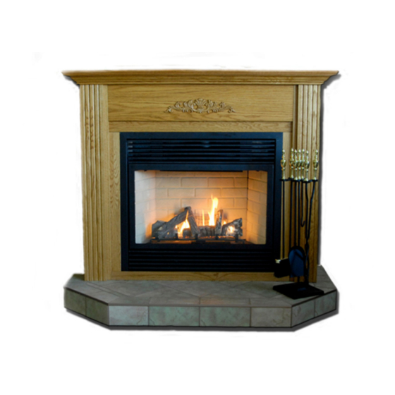
- Page 1 Owners Manual of direct-vent gas fireplace DV36(NG) Legend fireplace co.,ltd 1248...
- Page 2 Installers Guide - Do not store or use gasoline or other flammable vapors and liquids in the vicinity of this or any other appliance. - What to do if you smell gas • Do not try to light any appliance. •...
-
Page 3: Safety And Warning Information
SAFETY AND WARNING INFORMATION NOTE: NOT INTENDED FOR FIREPLACE INSERT. DO NOT MODIFY THIS APPLIANCE. DO NOT PLACE ARTICLES ON OR AGAINST THIS APPLIANCE. DO NOT USE OR STORE FLAMMABLE MATERIALS NEAR THIS APPLIANCE. DO NOT SPRAY AEROSOLS IN THE VICINITY OF THIS APPLIANCE WHILE IT IS IN OPERATION. DO NOT MODIFY THIS APPLIANCE. -
Page 4: Table Of Contents
Section 1: Approvals and Codes ..........……………….5 Appliance Certification..............……………..5 Installation Codes................……………..5 Section 2: Getting Started ............……………..5 Introducing the legend Gas Fireplaces .........………………….. 5 Pre-installation Preparation ............…………….5 Section 3: Installing the Fireplace ..........……………..6 Constructing the Chase ..............……………..6 Step 1 Locating the Fireplace ........... -
Page 5: Section 1: Approvals And Codes
Introducing the legend Gas Fireplaces Legend direct vent gas fireplaces are designed to operate with all combustion air siphoned from outside of the building and all exhaust gases expelled to the outside. The information contained in this Installers Guide, unless noted otherwise, applies to all models and gas control systems. -
Page 6: Section 3: Installing The Fireplace
AND Air Kit for combustion air. Note: Insulated intake ducting is required in cold climates. The legend Warranty will be voided by, and legend disclaims any responsibility for, the following actions: • Installation of any damaged fireplace or vent system component. -
Page 7: Step 1 Locating The Fireplace
Factory-built fireplace chases should be constructed in the manner of all outside walls of the home to prevent cold air drafting problems. The chase should not break the outside building envelope in any manner. This means that the walls, ceiling, base plate and cantilever floor of the chase should be insulated. -
Page 8: Step 2 Framing The Fireplace
Step 2. Framing the Fireplace Fireplace framing can be built before or after the fireplace is set in place. Framing should be positioned to accommodate wall coverings and fireplace facing material. UNIT ASSEMBLY PRIOR TO INSTALLATION The Top Facing Support, the Side Nailing Strips and the 2 Top Standoffs must be correctly positioned and attached to the top before unit is slipped into position. -
Page 9: Step 3 Installing The Vent System
Step 3. Installing the Vent System A. Vent System Approvals This model is approved to use Flo-Met direct vent components and terminations .Approved vent system components are labeled for identification. The pipe is tested to be run inside an enclosed wall. - Page 10 Flue Outlet Settings Horizontal Flue Configuration: Fully Open Vertical Flue Configuration: Baffle set to 28mm Open (Flue Termination @ 4.5m above floor level)* Vertical Flue Configuration: Baffle set to 32mm Open (Flue Termination @ 2.5m above floor level)* *Flue outlet opening was measured from widest point of the circular opening to the edge of the adjustment plate.
- Page 11 Horizontal venting with one 90º elbow. Options V Minimum H Maximum 914.4 304.8 1524 609.6 2438.4 914.4 3048 2438.4 3048 2743.2 2438.4 3048 1524 3352.8 914.4 Note: for longer pipe runs, the total minimum vertical length is 3352.8mm and the total maximum horizontal length is 914.4mm.
- Page 12 Horizontal venting with three 90º elbows. Options V1 V1+V2 H1+H2 609.6 609.6 914.4 304.8 914.4 1219.2 1219.2 609.6 914.4 1828.8 1524 914.4 914.4 2438.4 1828.8 1219.2 1219.2 3048 2133.6 1524 1524 3352.8 2438.4 1828.8 1828.8 3657.6 2743.2 2133.6 2133.6 3962.4 3048 Note: for longer pipe runs, the total minimum vertical length is 3962.4mm and the total maximum horizontal length is 3048mm.
- Page 13 Direct Vent Zero Clearance Top Exit Vertical Flue Kit Installation instructions This flue kit has been manufactured in accordance with AS5601 2002.To ensure safety this flue kit must be installed as outlined in these instructions. Heater and flue clearancs from combustible walls and framing must be in accordance with these instructions and AG501.
- Page 14 5) Mark the wall for a 254x254mm square hole. The center of the square hole should line up with the centerline of the horizontal pipe. Cut and frame the square hole in the exterior wall where the vent will be terminated. Note: a) The horizontal run of vent must be level, or have a 6.35mm rise for every 305mm of run towards the termination.
-
Page 15: Vertical Installations
B. Installing vertical terminations Installing rigid pipe vent system: Horizontal venting with two 90º elbows. Options V1+V2 Minimum Maximum Minimum 914.4 609.6 304.8 1524 914.4 609.6 1828.8 1219.2 914.4 2133.6 1524 1219.2 2438.4 1828.8 1524 2743.2 2133.6 Note: for longer pipe runs, the total minimum vertical length is 2133.6mm and the total maximum horizontal length is 2743.2mm. - Page 16 1) Maintain the 32mm clearances (air spaces) to combustibles when passing through ceilings, walls, roofs, enclosures, attic rafter, or other nearby combustible surfaces. Do not pack air spaces with insulation. Check the "Venting Arrangement" section for the maximum vertical rise of the venting system and the maximum horizontal offset limitations.
- Page 17 The upper half of the flashing is installed under the roofing material and not nailed down until the chimney is installed. This allows for small adjustments. 6) Continue to assemble pipe lengths. Note: If an offset is necessary in the attic to avoid obstructions, it is important to support the vent pipe every 3 feet, to avoid excessive stress on the elbows, and possible separation.
-
Page 19: Step 4 Positioning, Leveling, And Securing The Fireplace
Step 4. Positioning, Leveling, and Securing the Fireplace The diagram below shows how to properly position, level, and secure the fireplace. • Place the fireplace into position. • Level the fireplace from side to side and from front to back. •... -
Page 20: Step 6 The Gas Supply Line
Step 6. The Gas Supply Line GAS LINE INSTALLATION The gas line is brought through the right of the appliance. The gas valve is situated on the right hand side of the unit and the gas inlet is on the right hand side of the valve. The gas line connection may be made of rigid pipe, copper pipe (If you are using rigid pipe, ensure that the valve can be removed for servicing.) Ensure the appliance shall be installed only by authorised persons and in accordance with the... - Page 21 1 around the thermocouple and 1 fl owing across the burner (it does not have to be touching the burner). Note: If you have an incorrect flame pattern, contact your LEGEND dealer for further instructions Incorrect flame pattern will have small, probably yellow flames, not coming into proper contact with the rear burner or thermopile or thermocouple.
-
Page 22: Step 7 Gas Pressure Requirements
S.I.T. VALVE DESCRIPTION Step 7. Gas Pressure Requirements Pressure requirements for legend gas fireplaces are shown in the table below. Pressure Natural Gas Inlet Gas Pressure 1.13kPa Manifold Pressure 0.87kPa Caution: Ensure that the wires do not touch any hot surfaces and are away from sharp edges. -
Page 23: Step 8 Finishing
CAUTION: LABEL ALL WIRES PRIOR TO DISCONNECTION WHEN SERVICING CONTROLS. WIRING ERRORS CAN CAUSE IMPROPER AND DANGEROUS OPERATION. VERIFY PROPER OPERATION AFTER SERVICING. Step 8. Finishing The following diagram shows the minimum vertical and corresponding maximum horizontal dimensions of fireplace mantels or other combustible projections above the top front edge of the fireplace. -
Page 24: Step 9 Positioning Logs, And Ember Material
Hearth Extensions Step 9. Position brick panels, Logs, log Ember and glowing Material and remote control. Brick panels (optional panel models may be installed in different manner) 1) Undo the bottom 2 door latches and open and remove glass door. Remove logs. Note: The logs must not be in the unit. - Page 25 Positioning the Logs...
- Page 26 The logs have been packed separately, refer to thefollowing pics to position the log ember, the glowing material and log set. If sooting occurs, the logs might need to be repositioned slightly to avoid excessive flame impingement. If logs are broken do not use the unit until they are replaced. Broken logs can interfere with the pilot operation.
- Page 27 REMOTE CONTROL( ( ( ( Optional) ) ) ) Use the LEGEND Remote Control Kit approved for this unit. Use of other systems may void your warranty. The remote control kit comes with a hand held transmitter, a receiver and a wall mounting plate.
-
Page 28: Step 10 Before Lighting The Fireplace
the receiver. Install the receiver and its cover in the wall. Switch the remote receiver to "remote" mode. The remote control is now ready for operation. Warning: If the supply cord is damaged, it must be replaced by the manufacturer, its service agent or similarly qualified persons in order to avoid a hazard. -
Page 29: Shutdown Procedure
All are normal operating sounds and should not be considered as defects in your appliance. Blower: LEGEND gas appliances use high tech blowers to push heated air farther into the room. It is not unusual for the fan to make a "whirring" sound when ON. This sound will increase or decrease in volume depending on the speed setting of your fan speed control. - Page 30 THE LIGHTING PLATE INSTRUCTIONS...
-
Page 31: Section 4: Maintaining And Servicing Your Fireplace
Maintaining and Servicing Your Fireplace Part list: Warning: Servicing shall be carried out only by authorized personnel. A set of DV36 includes the unit and the log set packed separately. 1. Standard log set includes 6 pcs of log from A to F, one for each. - Page 32 2. fireplace body packed separately. Name Name Bottom grill Side and back frame Top grill Spacer Front frame Air box outside guider part2 Mesh frame Air box assembly Glass assembly Side standoff Glass frame Inner exhausting base Glass frame hook spring Air output guider part 1 Gas valve Air output guider part 2...
-
Page 33: Cleaning And Maintenance
CLEANING AND MAINTENANCE Make sure the gas valve knob is in the “OFF” position. Wait at least five (5) minutes before starting maintenance. Fireplace must be cold before starting maintenance. VENTING SYSTEM A qualified agency should examine the venting system annually. CLEANING GLASS CAUTION Let glass cool before cleaning. -
Page 34: Troubleshooting
TROUBLESHOOTING STANDING PILOT IGNITION SYMPTOM POSSIBLE CAUSE ACTION 1. Spark ignitor will A. Wire disconnected. A. Open door and check to make sure wire not light pilot. B. Defective ignitor. is connected to ignitor. C. No gas or low gas B. - Page 35 to the thermopile, adjust pilot flame. C. Check thermopile wire connections to make sure all are tight and that the thermopile is fully inserted into pilot assembly. Check thermopile with a millivolt meter. Connect leads to TP and TP/TH terminals on the control valve. If meter reading is below 325 mV, D.
- Page 36 THE FOLLOWING INFORMATION MUST BE RECORDED BY THE INSTALLER FOR WARRANTY PURPOSES AND FUTURE REFERENCE. Legend Model: _____________________________ Name of Owner: Address: Name of Installer: Address: Phone: Name of Dealer: Address: Phone: Phone: Manufactured by LEGEND FIREPLACE CO., LTD For service and spare parts contact (08) 8349 8332...
-
Page 37: Limited Lifetime Warranty Policy
After installation, if any of the components manufactured by LEGEND in the appliance are found to be defective in materials or workmanship, LEGEND will, at its option, replace or repair the defective components at no charge to the original owner.
Need help?
Do you have a question about the DV36NG and is the answer not in the manual?
Questions and answers