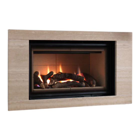
Ethos Landscape & Portrait Remote Control - Log, Pebble & Driftwood Effect - Inset Live Fuel Effect Radiant Convector Fire Installation and Users Instructions These instructions should be read by the installer before installation and then should be handed to the end user when the installation is complete.
CONTENTS SECTION PAGE Notes for the Installer and End User Installation Requirements Installation Procedure Installation - Class One Unlined Chimney Installation - Class One Flue with Flexible Liner Installation - False Drywall Chimney Breast & Twin Wall Flue Installation - Slips Kit Installation - Clip-on surrounds Commissioning Technical Data...
Before installation, ensure that the local conditions, (identification of gas type and pressure) and the adjustment of the appliance are compatible. Never place combustible material directly in front of this appliance. Floor covering such as carpet is acceptable but must be a minimum of 300mm from the incandescent flame. Ethos Landscape 825mm 300mm...
225mm x 225mm (9” x 9”) or a lined flue with a minimum diameter of 125mm (5”), with the fireplace components conforming to BS1251, or a builders opening a minimum of: Ethos Landscape - 466mm high and 757mm wide with a minimum depth of 325mm Ethos Portrait - 622mm high and 757mm wide with a minimum depth of 325mm to allow sufficient volume for debris collection (unlined chimney 12 dm3 and lined 2 dm3).
Page 6
INSTALLATION REQUIREMENTS FLUE FLOW TEST A flue flow test (smoke test) is carried out to check the effectiveness of the flue and to ensure that there is no leakage into another part of the premises (including any loft), or as appropriate other adjoining premises (this is particularly important where a number of chimneys combine into a multiple stack).
INSTALLATION PROCEDURE 30° Fig. 3 1. Remove the two screws at the bottom of the glass 2 x Securing Screws door panel (Fig. 2). Fig. 2 2. Hinge the door upwards by approximately 30° (Fig. 2). 3. Slide the door to the right by 10mm and remove the Black Internal Top Panel door from it’s hinges (Fig.
INSTALLATION - Class One Unlined Chimney 1. Remove the 5” flue spigot adaptor and cap off the outlet hole with the slide-in cover plate provided (Fig. 6). 2. Bend the tab up to secure (Fig. 7). 3. Remove the rear flue outlet cover plate, this is secured with two pozi head screws, this cover is no longer needed and may be discarded (Fig.
INSTALLATION - Class One Flue with Flexible Liner Ensure that the existing fire place lintel is made of non-combustible material. Fig. 10 1. Measure down 475mm (Ethos Landscape), 630mm (Ethos Portrait) from the underside of the fireplace lintel Flexible Flue and make a mark on the wall.
INSTALLATION - False Drywall Chimney Breast & Twin Wall Flue Steel Drywall Frame Kit 1. Construct a false chimney breast using a suitable non-combustible steel frame construction kit (Fig. 15). 2. Ensure that there are two vertical steel battens placed to allow the flange of the fire box to be screwed to them (Fig.
Page 11
INSTALLATION - False Drywall Chimney Breast & Twin Wall Flue 9. Locate the drywall fixing kit onto the fire box and secure with the countersunk screws provided into the fixing bushes (Fig. 19 & 20). It may be preferential to use the Drywall Fixing Kit to secure the fire chassis to the chimney breast structure.
INSTALLATION - Clip-on surrounds For Clip-on surrounds, the fire must be installed so the fire box flange is visible in the room. This will enable the magnets to secure the surround to the flange. 1. Prepare the builder’s opening following the previous pages.
Page 14
INSTALLATION - Clip-on surrounds Fixing Holes 9. Secure the fire box to the wall using the fixing holes provided in the fire box flange (Fig. 29). 10. Carefully locate the magnetic surround on to the fire Fixing Holes box flange (Fig. 31 & 32). Fig.
Fig. 35 check working pressure and gas rate see (page 16). Note: the gas rate is factory set and is not adjustable without specialised Legend equipment. 12. Refit heat shield, gas connection cover panel must be always fitted (Fig. 36).
Page 16
COMMISSIONING Refit all the back-side liner components and slide black top panel back into position (Fig. 37). Black Internal Top Panel Fig. 37a 13. At this stage locate the burner top Burner grille on the tabs provided before slotting Top Grill the remaining liner blocks into position.
Component Layout Instructions (pages 26-29) are adhered to. Under no circumstances should additional/extra logs be added. Only genuine Legend replacement parts should be used. Order Ref: ETHLOG01 2. Oxygen Depletion Sensing Pilot - In the unlikely event of a pilot failure, the pilot assembly should only be replaced by a Gas Safe Registered Engineer.
TROUBLE SHOOTING (GAS SAFE ENGINEER ONLY) Code Comment Apperance Possible Cause Action TESC locked due to Red Led is Temporary air Reset control by pressing start button for 1 second and releasing. Then press again the same way failed ignition permanently on disturbance around pilot to attempt a normal start command.
Page 19
TROUBLE SHOOTING (GAS SAFE ENGINEER ONLY) Code Comment Apperance Possible Cause Action Button (-) is shorted Check for contamination Clean as necessary. Replace switch panel as necessary if damaged or too contaminated. Reset and try again to other buttons / damage and replace disconnect wired control panel and try again –...
USERS INSTRUCTIONS Warnings All parts of the appliance become hot while running and should therefore be considered to be working surfaces. A suitable guard may be required to take account of special hazards that exist in nurseries and other places where there are young children, aged or infirm persons. Curtains are not to be placed directly above the appliance.
USERS INSTRUCTIONS Handset Ensure the Power Isolator Switch on the front corner of Fire Control is in the on position (I). Note: For safety reasons a button must be pressed and released for the command to be recognised. Keeping hold of the button when pressing (unless otherwise instructed) will not be recognised as a command press. Grasp around the handset to unlock its functions.
Page 22
Note: the legend at the bottom shows the battery condition of both the batteries in the hand set and in the fire control alternately. RC = Remote Control handset and FC = Fire control. The...
Page 23
USERS INSTRUCTIONS Paging the handset If you have misplaced the handset you can page it by pressing the + button only on the fire control for around 5 seconds. The handset will flash and make a noise to help you to locate it. Once you pick up the TESC it knows you hold it and so the sound stops.
Page 24
USERS INSTRUCTIONS Snooze mode in Thermostatic mode The same thing as above can be done before or during a thermostatic mode operation (see below). Thermostatic mode only The handset has within it a thermostat sensor and this can be set so the fire will heat the room to match the temperature set in the handset.
CLEANING AND MAINTENANCE It is recommended that this appliance is serviced at regular 12 monthly intervals. The chimney or flue should also be checked regularly to ensure that all products of combustion are entering the flue and there is no excessive build up of soot.
The logs must be kept away from children at all times. Never put additional logs on the fire. Never use logs other than those originally supplied, or genuine Legend Spare Parts. 1. Place the rear ceramic panels into position.
Page 27
LOG LAYOUT INSTRUCTIONS CONTINUED 9. Place the remaining logs as shown in the photographs below. It is very important that all the logs are used and arranged as shown in order to achieve the desired flame picture. It may be necessary to remove some or all of the logs to clean them at some time. Cleaning must only be done using a soft brush.
The pebbles & driftwood must be kept away from children at all times. Never put additional pebbles & driftwood on the fire. Never use pebbles & driftwood other than those originally supplied, or genuine Legend Spare Parts. 1. Place the rear ceramic panels into position.
Page 29
PEBBLE & DRIFTWOOD LAYOUT INSTRUCTIONS CONTINUED 9. Place the remaining pebbles and driftwood as shown in the photographs below. It is very important that all the pebbles and driftwood are used and arranged as shown in order to achieve the desired flame picture.
TROUBLE SHOOTING (USER) Non Display handset with pilot burner If the fire does not start at the first attempt it may retry several times to do so. At the end of trying if it cannot ignite the burner; it will show a RED light on the handset and on the fire control and stop the fire. •...
Page 32
Unit 404 Glenfield Park Business Centre Blakewater Road Blackburn Lancashire BB1 5QH Tel: 01254 695244 Fax: 01254 695255 Web: www.legend-fires.com Email: info@legend-fires.com Issue 2 - 10/3/14...