Table of Contents
Advertisement
Quick Links
Download this manual
See also:
Owner's Manual
Advertisement
Table of Contents

Subscribe to Our Youtube Channel
Related Manuals for B2 Audio M1u


Summary of Contents for B2 Audio M1u
- Page 1 MODEL: M1u Product id:M1UD13 OWNER’S MANUAL...
-
Page 2: Table Of Contents
Foreword We congratulate you with your decision to purchase our reveered niche amplifiers. Every product developed by implements the keystones of our company philosophy; Optimum sound reproduction within its range, etter ass & high performance. These elements will enable you to reproduce music the way you prefer. Our amplifiers features a unique design, a variety of applications &... -
Page 3: Design Features
1. Design features Circuit Configuration HI-EF Class D Mono Frequency Response : 15 Hz ~ 250 Hz Signal to Noise Ratio : 100dB Input Sensitivity : 6V ~ 0.2V Input Level Selector Crossover : 24dB / Oct Low Pass Crossover Range : 35 Hz ~ 250 Hz Subsonic Crossover Range : 10 Hz ~ 50 Hz... -
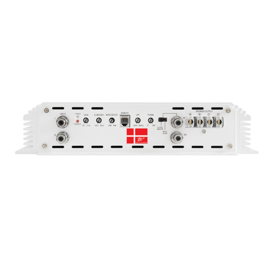
Page 4: Panel Layout
Adjusts the subsonic cut off point to eliminate frequencies within the filter’s range. OUTPUT MASTER / INPUT SLAVE For daisy chain connection of 2 M1u amplifiers. SPEAKER OUTPUTS Minimum impedance is 2 Amplifier connection to the loudspeakers. - Page 5 2. Panel layout +12V (POWER CONNECTION) GND (GROUND CONNECTION) For connection to the positive terminal For connection to the chassis’ ground. For optimum performance 0 gauge cable is of the battery (+12V). required, all of them using common ground For optimum performance 0 gauge cable connected with cable of equal length.
-
Page 6: Installation
3. Installation 3.1 Installation considerations If you choose to install the amplifier by yourself, please read the owner’s manual carefully. Before you start your installation, please take all steps into consideration. If in doubt, please go to www.b2audio.com for authorized distributors / dealers that will be able to configure your set up &... -
Page 7: Wiring Layout
3.3 Wiring layout Head unit +12V, GND, REM connection chart Remote turn on Keep GROUND of equal length. This drawing is for illustration purposes only! 850A (External fuses) We recommend using 12 AWG speaker cables to obtain increased performance. Run 12 AWG speaker cables from your speakers to the amplifier’s mounting location Keep the speaker cables seperate from the power cables and and the amplifier’s input cables. -
Page 8: Speaker Wiring Diagram
3.31 Speaker wiring diagram SWEET LIKE DANISH CAUTION The minimum impedance as 1 unit is 1 . In a daisy chain configuration the minimum impedance is 2 . Speaker Impedance 1~8 ohms Head unit MASTER AMPLIFIER SWEET LIKE DANISH Daisy chain connection allows linking of 2 amplifiers to work as 1 single amplifier. -
Page 9: Troubleshooting
4. Troubleshooting The protection circuits of the amplifier prevents severe damages from faulty conditions & improper use. The protection indicatior will switch on due to short circuit connection & speaker overload, thus the amplifier will be turned off. Prior to inspecting the occurred problem, turn all levels down & all power off, then carefully check the installation for wiring mistakes, shorts or faulty ground (GND).
Need help?
Do you have a question about the M1u and is the answer not in the manual?
Questions and answers