Table of Contents
Advertisement
Quick Links
Advertisement
Table of Contents

Related Manuals for B2 Audio M1u


Summary of Contents for B2 Audio M1u
- Page 1 MODEL: M1u Product id:M1UD13 OWNER’S MANUAL...
-
Page 2: Table Of Contents
Foreword We thank you for purchasing our amplifiers. Your decision to be part of something different is what we strive for. Our products reflects who we are, going to the extent to deliver you our finest comes natural. Our amplifiers are engineered to accomondate a variety of applications. Whether it is SPL or SQ, the sound provided will be clean &... -
Page 3: Design Features
Items not installed by authorized dealers will be warrantied for 30 days from the original purchase. Original sales receips must be accompanied with all returns.The warranty applies to the original purchaser of the product & it being sold by authorized B2 audio dealers. -
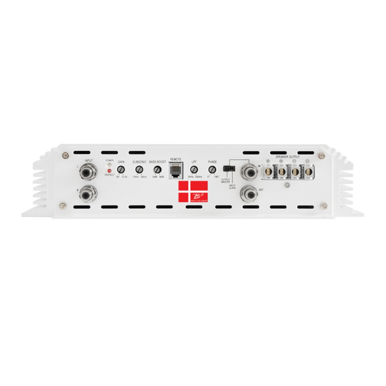
Page 4: Panel Layout
Adjusts the subsonic cut off point to eliminate frequencies within the filter’s range. OUTPUT MASTER / INPUT SLAVE For daisy chain connection of 2 M1u amplifiers. SPEAKER OUTPUTS Minimum impedance is 2 Amplifier connection to the loudspeakers. - Page 5 2. Panel layout +12V (POWER CONNECTION) GND (GROUND CONNECTION) For connection to the positive terminal For connection to the chassis’ ground. For optimum performance 0 gauge cable is of the battery (+12V). required, all of them using common ground For optimum performance 0 gauge cable connected with cable of equal length.
-
Page 6: Installation
Connect the power cables to the power terminal labeled as +12V. The M1u is not equipped with fuses, so fusing at the battery as well as the amplifier is required. Connect one end of the fuse holder to the power cable and the other end of the fuse holder to the positive battery terminal within 20 cm / 8’’... -
Page 7: Wiring Layout
3.3 Wiring layout Head unit +12V, GND, REM connection chart Remote turn on Keep GROUND of equal length. This drawing is for illustration purposes only! 850A (External fuses) We recommend using 12 AWG speaker cables to obtain intended performance. Run 12 AWG speaker cables from your speakers to the amplifier’s mounting location. Keep the speaker cables seperate from the power cables and and the amplifier’s input cables. -
Page 8: Speaker Wiring Diagram
3.31 Speaker wiring diagram SWEET LIKE DANISH CAUTION The minimum impedance as 1 unit is 1 . In a daisy chain configuration the minimum impedance is 2 . Speaker Impedance 1~8 ohms Head unit MASTER AMPLIFIER SWEET LIKE DANISH Daisy chain connection allows linking of 2 amplifiers to work as 1 single amplifier. -
Page 9: Troubleshooting
4. Troubleshooting The protection circuits of the amplifier prevents severe damages from faulty conditions & improper use. The protection indicatior will switch on due to short circuit connection & speaker overload, thus the amplifier will be turned off. Prior to inspecting the occurred problem, turn all levels down & all power off, then carefully check the installation for wiring mistakes, shorts or faulty ground (GND). - Page 10 Items not installed by authorized dealers will be warrantied for 30 days from the original purchase. Original sales receips must be accompanied with all returns.The warranty applies to the original purchaser of the product & it being sold by authorized B2 audio dealers.
Need help?
Do you have a question about the M1u and is the answer not in the manual?
Questions and answers