Sign In
Upload
Download
Table of Contents
Contents
Add to my manuals
Delete from my manuals
Share
URL of this page:
HTML Link:
Bookmark this page
Add
Manual will be automatically added to "My Manuals"
Print this page
×
Bookmark added
×
Added to my manuals
Manuals
Brands
Supermicro Manuals
Motherboard
Supero X8DTL-3
User manual
Supermicro SuperO X8DTL-3 User Manual
Hide thumbs
1
2
3
4
5
Table Of Contents
6
7
8
9
10
11
12
13
14
15
16
17
18
19
20
21
22
23
24
25
26
27
28
29
30
31
32
33
34
35
36
37
38
39
40
41
42
43
44
45
46
47
48
49
50
51
52
53
54
55
56
57
58
59
60
61
62
63
64
65
66
67
68
69
70
71
72
73
74
75
76
77
78
79
80
81
82
83
84
85
86
87
88
89
90
91
92
93
94
95
96
97
98
99
100
101
page
of
101
Go
/
101
Contents
Table of Contents
Troubleshooting
Bookmarks
Table of Contents
About this Manual
About this Motherboard
Contacting Supermicro
Table of Contents
Chapter 1 Introduction
Overview
Chipset Overview
Special Features
PC Health Monitoring
ACPI Features
Slow Blinking LED for Suspend-State Indicator
Main Switch Override Mechanism
Wake-On-LAN (WOL)
Power Supply
Super I/O
Overview of the Winbond WPCM450 Controller (for X8DTL-3F/X8DTL-If Only)
Chapter 2 Installation
Static-Sensitive Devices
Precautions
Unpacking
Motherboard Installation
Tools Needed
Installation Instructions
Processor and Heatsink Installation
Installing a CPU Heatsink
Installing and Removing the Memory Modules
Installing & Removing Dimms
Control Panel Connectors/Io Ports
Back Panel Connectors/Io Ports
ATX PS/2 Keyboard and PS/2 Mouse Ports
Universal Serial Bus (USB)
Serial Ports
Video Connector
Ethernet Ports
Front Control Panel
Front Control Panel Pin Defi Nitions
NMI Button
Power LED
Hdd Led
NIC1/NIC2 LED Indicators
Overheat (Oh)/Fan Fail/Front UID LED
Power Fail LED
Reset Button
Power Button
Connecting Cables
Power Connectors
Fan Headers
Chassis Intrusion
Internal Speaker
Power Led/Speaker
Wake-On-LAN
Overheat Led/Fan Fail (JOH1)
T-SGPIO 1/2 & 3-SGPIO 1/2 Headers
I-Button
Power SMB (I 2 C) Connector
Ipmb
Unit Identifi Cation Switch/Leds
Jumper Settings
Explanation of Jumpers
GLAN Enable/Disable
CMOS Clear
Watch Dog Enable/Disable
I 2 C Bus to PCI-Exp. Slots
VGA Enable
SAS Enable/Disable (X8DTL-3/X8DTL-3F Only)
SAS RAID Mode Select (X8DTL-3/X8DTL-3F Only)
Manufacture Mode (X8DTL-If/-3F)
ME Recovery (X8DTL-If/-3F)
Onboard LED Indicators
GLAN Leds
IPMI Dedicated LAN Leds (X8DTL-If/-3F)
SAS Heartbeat LED (X8DTL-3/-3F)
BMC Heartbeat LED (X8DTL-If/3F)
Onboard Power LED
Rear UID LED
Serial ATA and SAS Connections
Serial ATA Ports
SAS Ports (X8DTL-3/X8DTL-3F Only)
Chapter 3 Troubleshooting
Troubleshooting Procedures
Before Power on
No Power
No Video
Losing the System's Setup Confi Guration
Memory Errors
Technical Support Procedures
Frequently Asked Questions
Returning Merchandise for Service
Chapter 4 BIOS
Introduction
Starting BIOS Setup Utility
How to Change the Confi Guration Data
Starting the Setup Utility
Main Setup
Advanced Setup Confi Gurations
Processor and Clock Options
Advanced Chipset Control
Security Settings
Boot Confi Guration
Exit Options
BIOS Recovery
How to Recover the AMIBIOS Image (-The Main BIOS Block)
4.7.1 Boot Sector Recovery from a USB Device
4.7.2 Boot Sector Recovery from an IDE CD-ROM
Boot Sector Recovery from a Serial Port ("Serial Flash")
Appendix A BIOS Error Beep Codes
A-1 BIOS Error Beep Codes
Appendix B Installing the Windows os
B-1 Installing the Windows os to a RAID System
B-2 Installing the Windows os to a Non-RAID System
Appendix C Software Installation Instructions
C-1 Installing Software Programs
C-2 Confi Guring Supero Doctor III
Advertisement
Quick Links
1
Overview
Download this manual
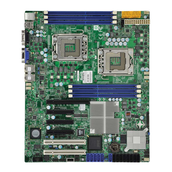
USER'S MANUAL
Revision 1.0b
X8DTL-3
X8DTL-i
X8DTL-3F
X8DTL-iF
Table of
Contents
Previous
Page
Next
Page
1
2
3
4
5
Advertisement
Table of Contents
Need help?
Do you have a question about the SuperO X8DTL-3 and is the answer not in the manual?
Ask a question
Questions and answers
Related Manuals for Supermicro SuperO X8DTL-3
Motherboard Supermicro Supero X8DTH-6F User Manual
Super micro - server motherboard (96 pages)
Motherboard Supermicro X8DTH-6 Quick Reference Manual
(1 page)
Motherboard Supermicro Supero X8DTL-i User Manual
(101 pages)
Motherboard Supermicro Supero X8DTL-iF User Manual
(101 pages)
Motherboard Supermicro SUPERO X8DTN+ User Manual
(99 pages)
Motherboard Supermicro X8DTU-LN4F+ User Manual
(107 pages)
Motherboard Supermicro Supero X8DTU-F User Manual
Super micro - server motherboard (95 pages)
Motherboard Supermicro X8DTU User Manual
(92 pages)
Motherboard Supermicro X8DTE User Manual
(97 pages)
Motherboard Supermicro X8DT6 User Manual
(97 pages)
Motherboard Supermicro X8DTE-F User Manual
(97 pages)
Motherboard Supermicro X8DTN+-F-LR User Manual
(107 pages)
Motherboard Supermicro X8DTG-QF Quick Reference Manual
(1 page)
Motherboard Supermicro Supero X8DAE User Manual
(91 pages)
Motherboard Supermicro Supero X8DAH+-F User Manual
Super micro - x8dah+-f server motherboard (103 pages)
Motherboard Supermicro Supero X8DAi User Manual
(91 pages)
This manual is also suitable for:
Supero x8dtl-i
Supero x8dtl-3f
Supero x8dtl-if
Table of Contents
Save PDF
Print
Rename the bookmark
Delete bookmark?
Delete from my manuals?
Login
Sign In
OR
Sign in with Facebook
Sign in with Google
Upload manual
Upload from disk
Upload from URL


Need help?
Do you have a question about the SuperO X8DTL-3 and is the answer not in the manual?
Questions and answers