Table of Contents
Advertisement
Advertisement
Table of Contents

Subscribe to Our Youtube Channel
Related Manuals for Supermicro X8DT6


Summary of Contents for Supermicro X8DT6
- Page 1 X8DT6 X8DTE X8DT6-F X8DTE-F USER’S MANUAL Revision 1.1...
- Page 2 This product, including software and docu- mentation, is the property of Supermicro and/or its licensors, and is supplied only under a license. Any use or reproduction of this product is not allowed, except as expressly permitted by the terms of said license.
-
Page 3: About This Manual
QuickPath Interconnect (QPI) Technology, providing the next generation point-to- point system interface to replace the current Front Side Bus. With the 5500/5600 Series Processor platform built in, the X8DT6/X8DT6-F/X8DTE/X8DTE-F offers substantial enhancement in system performance with increased bandwidth and unprecedented scalability optimized for high-end servers, High Performance Com- puting (HPC) systems and intensive applications. - Page 4 X8DT6/X8DT6-F/X8DTE/X8DTE-F User's Manual Warning: Important information given to ensure proper system installation or to prevent damage to the components. Note: Additional Information given to differentiate various models or to ensure correct system setup.
-
Page 5: Contacting Supermicro
Super Micro Computer, Inc. 980 Rock Ave. San Jose, CA 95131 U.S.A. Tel: +1 (408) 503-8000 Fax: +1 (408) 503-8008 Email: marketing@supermicro.com (General Information) support@supermicro.com (Technical Support) Web Site: www.supermicro.com Europe Address: Super Micro Computer B.V. Het Sterrenbeeld 28, 5215 ML... -
Page 6: Table Of Contents
Slow Blinking LED for Suspend-State Indicator ..........1-11 Main Switch Override Mechanism ..............1-11 Wake-On-LAN (WOL) ..................1-11 Power Supply ....................1-12 Super I/O ....................... 1-12 Overview of the Winbond WPCM450 Controller (For X8DT6-F/X8DTE-F Only) ........................1-13 Chapter 2 Installation Static-Sensitive Devices .................. 2-1 Precautions ..................... 2-1 Unpacking ....................... - Page 7 Internal Speaker ..................2-23 Power LED/Speaker ................. 2-23 Wake-On-LAN ..................2-24 Overheat LED/Fan Fail (JOH1) ..............2-24 T-SGPIO Headers ..................2-25 RAIDKey Header (Optional for X8DT6/X8DT6-F only) ......2-25 Power SMB (I C) Connector ..............2-26 IPMB I C SMB ..................2-26 DOM Power Connector ................
- Page 8 X8DT6/X8DT6-F/X8DTE/X8DTE-F User's Manual Chapter 3 Troubleshooting Troubleshooting Procedures ................3-1 Before Power On .................... 3-1 No Power ......................3-1 No Video ......................3-2 Losing the System’s Setup Confi guration ............3-2 Memory Errors ....................3-2 Technical Support Procedures ................ 3-3 Frequently Asked Questions ................
-
Page 9: Chapter 1 Introduction
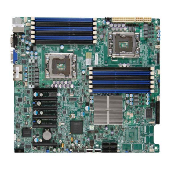
Checklist Congratulations on purchasing your computer motherboard from an acknowledged leader in the industry. Supermicro boards are designed with the utmost attention to detail to provide the highest standards in quality and performance. Check that the following items have all been included with your motherboard. If anything listed here is damaged or missing, contact your retailer. - Page 10 X8DT6/X8DT6-F/X8DTE/X8DTE-F User's Manual X8DT6/X8DT6-F Image Note: The drawings and pictures shown in this manual were based on the latest PCB Revision available at the time of publishing of the manual. The motherboard you’ve received may or may not look exactly the same as...
- Page 11 IPMI Dedicated LAN is for X8DT6-F/X8DTE-F only. SAS connectors, jumpers, and the LSI 2008 SATA 2 chip are available on the X8DT6/X8DT6-F only. For SAS RAID confi guration, refer to the LSI User Guide posted on our website @ http://www.supermicro.com/support/manuals/ IPMI 2.0 and the Dedicated LAN (w/KVM support) are available on the...
- Page 12 X8DT6/X8DT6-F/X8DTE/X8DTE-F User's Manual Motherboard Layout FAN5 P1-DIMM3A JPI2C1 JPW2 JPW1 JPW3 P1-DIMM3B FAN1 FAN6 P1-DIMM2A P1-DIMM2B P1-DIMM1A FAN7 P1-DIMM1B CPU2 CPU1 Fan CPU1 FAN2 P2-DIMM1B P2-DIMM1A P2-DIMM2B P2-DIMM2A P2-DIMM3B FAN8/ CPU2 Fan P2-DIMM3A SLOT7 PCI-E 2.0 X8 FAN3 X8DT6/E Series Rev.
- Page 13 System/CPU Fan Headers (Fans 7~8: CPU Fans) Floppy Floppy Disk Drive Connector JIBTN1 RAIDKey for RAID 5 SAS support (optional for X8DT6/X8DT6-F) IPMB I C Header (for an IPMI card) (X8DTE-F/X8DT6-F) PWR LED/Speaker Header (Pins 4~7: Speaker) Front Panel Connector...
- Page 14 Intel 5520 chipset, including: the 5520 (IOH-36D) and the ICH10R (South Bridge). Expansion Slots • Three PCI-E 2.0 x8 slots (Slots 5~7) (X8DT6/X8DT6-F) • Four PCI-E 2.0 x8 slots (Slots 4~7) (X8DTE/X8DTE-F) • One PCI-E 2.0 x4 slot (Slot 3) •...
- Page 15 Up to eight USB 2.0 (Universal Serial Bus) (2 Backpanel USB Ports, 2 Front USB Headers, and 2 Type A Headers) • Super I/O: Winbond W83627HG • IPMI 2.0 with full KVM support (X8DT6-F/X8DTE-F only) (Note 3) Other • Wake-on-LAN (WOL) •...
- Page 16 X8DT6/X8DT6-F/X8DTE/X8DTE-F User's Manual #0-6 #1-6 #1-5 #0-5 #1-4 #0-4 #1-3 #0-3 #1-2 #0-2 #1-1 #0-1 Processor #2 Processor #1 PCI-E X8 Ports #7-8 Intel 5520 PCI-E X8 Ports #5-6 IOH-36D PCI-E X4 Ports #1-2 PCI-E X8 Ports #3-4 Ports PCI-E X8...
-
Page 17: Chipset Overview
Chapter 1: Introduction Chipset Overview Built upon the capability of the Intel 5520 platform, the X8DT6/X8DT6-F/X8DTE/ X8DTE-F motherboard provides the performance and feature set required for dual-processor-based high-end servers optimized for High Performance Comput- ing (HPC), Clustering, and intensive applications. The 5520 platform consists of the 5500/5600 Series (LGA 1366) processor, the 5520 (IO Hub), and the ICH10R (South Bridge). -
Page 18: Special Features
Setup section to change this setting. The default setting is Last State. PC Health Monitoring This section describes the PC health monitoring features of the X8DT6/X8DT6-F/ X8DTE/X8DTE-F. The motherboard has an onboard System Hardware Monitor chip that supports PC health monitoring. An onboard voltage monitor will scan these onboard voltages continuously: CPU1 Vcore/CPU2 Vcore, CPU1 DIMM/ CPU2 DIMM, 1.5V, 3.3Vcc (V), 3.3V SB (V), 12Vcc (V), 5Vin, and Battery Voltage. -
Page 19: Acpi Features
Chapter 1: Introduction environment or used with Supero Doctor II in Linux. Supero Doctor is used to notify the user of certain system events. You can also confi gure Supero Doctor to provide you with warnings when the system/CPU temperatures, voltages and fan speeds go beyond a pre-defi... -
Page 20: Power Supply
It is even more important for processors that have high CPU clock rates. The X8DT6/X8DT6-F/X8DTE/X8DTE-F can accommodate 24-pin ATX power sup- plies. Although most power supplies generally meet the specifi cations required by the CPU, some are inadequate. In addition, the two 12V 8-pin power connections are also required to ensure adequate power supply to the system. -
Page 21: Overview Of The Winbond Wpcm450 Controller (For X8Dt6-F/X8Dte-F Only)
SMI or SCI function pin. It also features auto power management to reduce power consumption. Overview of the Winbond WPCM450 Controller (For X8DT6-F/X8DTE-F Only) The Winbond WPCM450 Controller is a Baseboard Management Controller (BMC) that supports the 2D/VGA-compatible Graphics Core with the PCI interface, Virtual Media, and Keyboard/Video/Mouse Redirection (KVMR) modules. - Page 22 X8DT6/X8DT6-F/X8DTE/X8DTE-F User's Manual Notes 1-14...
-
Page 23: Chapter 2 Installation
Chapter 2: Installation Chapter 2 Installation Static-Sensitive Devices Electrostatic Discharge (ESD) can damage electronic com ponents. To prevent dam- age to your system board, it is important to handle it very carefully. The following measures are generally suffi cient to protect your equipment from ESD. Precautions •... -
Page 24: Motherboard Installation
X8DT6/X8DT6-F/X8DTE/X8DTE-F User's Manual Motherboard Installation All motherboards have standard mounting holes to fi t different types of chassis. Make sure that the locations of all the mounting holes for both motherboard and chassis match. Although a chassis may have both plastic and metal mounting fasteners, metal ones are highly recommended because they ground the mother- board to the chassis. -
Page 25: Processor And Heatsink Installation
Chapter 2: Installation Processor and Heatsink Installation When handling the processor package, avoid placing direct pressure on the label area of the fan. Notes: Always connect the power cord last and always remove it before adding, re- moving or changing any hardware components. Make sure that you install the processor into the CPU socket before you install the CPU heatsink. - Page 26 X8DT6/X8DT6-F/X8DTE/X8DTE-F User's Manual After removing the plastic cap, using your thumb and the index fi nger, hold the CPU at the north and south center edges. Align the CPU key, the semi- circle cutout, against the socket key, the notch below the gold color dot on the side of the socket.
-
Page 27: Installing A Cpu Heatsink
Chapter 2: Installation Installing a CPU Heatsink Do not apply any thermal grease to the heatsink or the CPU die because the required amount has already been ap- plied. Screw#1 Screw#2 Place the heatsink on top of the CPU so that the four mounting holes are aligned with those on the retention mechanism. - Page 28 X8DT6/X8DT6-F/X8DTE/X8DTE-F User's Manual Removing the Heatsink Warning: We do not recommend that the CPU or the heatsink be re- moved. However, if you do need to remove the heatsink, please follow the instructions below to uninstall the heatsink and prevent damage to the CPU or other components.
-
Page 29: Memory Installation
Chapter 2: Installation Memory Installation Note: Check the Supermicro web site for recommended memory modules. CAUTION Exercise extreme care when installing or removing DIMM modules to prevent any possible damage. Also note that the memory is interleaved to improve performance (See step 1). -
Page 30: Memory Support
X8DT6/X8DT6-F/X8DTE/X8DTE-F User's Manual Memory Support The X8DT6/X8DT6-F/X8DTE/X8DTE-F supports up to 192 GB of Registered ECC or up to 48 GB of Unbuffered ECC/Non ECC DDR3 1333 MHz/1066 MHz/800 MHz in 12 DIMMs. Please note that Memory Speed support is also depending on the type of CPU used in the motherboard. - Page 31 Chapter 2: Installation for the motherboards w/5500 Series Processors Memory Support installed RDIMM Population for the Motherboard w/5500 Processors Installed DIMM DIMMs DIMM Type (Reg.= Speeds (in MHz) Ranks per DIMM Slots per Populated Registered) (any combination; Channel per Channel SR=Single Rank, DR=Dual Rank, QR=Quad Rank)
- Page 32 X8DT6/X8DT6-F/X8DTE/X8DTE-F User's Manual • 1.35V DIMMs 1.35V RDIMM Population for the Motherboard w/5600 Processors Installed DIMM DIMMs DIMM Type Speeds (in MHz) Ranks per DIMM Slots per Populated (Reg.=Registered) (any combination; Channel per Channel SR=Single Rank, DR=Dual Rank, QR=Quad Rank) Reg.
-
Page 33: Control Panel Connectors/Io Ports
Back Panel I/O Port Locations and Defi nitions Back Panel Connectors Keyboard (Purple) PS/2 Mouse (Green) Back Panel USB Port 0 Back Panel USB Port 1 IPMI_LAN (X8DT6-F/X8DTE-F only) COM Port 1 (Turquoise) VGA (Blue) Gigabit LAN 1 Gigabit LAN 2 2-11... - Page 34 X8DT6/X8DT6-F/X8DTE/X8DTE-F User's Manual ATX PS/2 Keyboard and PS/2 PS/2 Keyboard/Mouse Pin Mouse Ports Defi nitions PS2 Keyboard PS2 Mouse The ATX PS/2 keyboard and PS/2 Pin# Defi nition Pin# Defi nition mouse are located next to the Back KB Data...
-
Page 35: Universal Serial Bus (Usb)
Pin # Defi nition Ground Ground No connection 1. Backpanel USB 0 2. Backpanel USB 1 3. Front Panel USB 2 4. Front Panel USB 3 5. Front Panel USB 4/5 6. Front Panel USB 6/7 X8DT6/E Series Rev. 2.01 2-13... -
Page 36: Serial Ports
X8DT6/X8DT6-F/X8DTE/X8DTE-F User's Manual Serial Ports Serial Ports-COM1/COM2 Pin Defi nitions Two COM connections (COM1 & Pin # Defi nition Pin # Defi nition COM2) are located on the motherboard. COM1 is located on the Backplane IO panel. COM2 is located close to the... -
Page 37: Ethernet Ports
IO backplane. In ad- P2V5SB SGND dition, an IPMI_dedicated_LAN is also TD0+ Act LED located on the X8DT6-F/X8DTE-F to TD0- P3V3SB provide KVM support for IPMI 2.0. All TD1+ Link 100 LED these ports accept RJ45 type cables. -
Page 38: Front Control Panel
These connectors are designed specifi cally for use with Supermicro server chassis. See the fi gure below for the descriptions of the various control panel buttons and LED indicators. Refer to the following section for descriptions and pin defi... -
Page 39: Front Control Panel Pin Defi Nitions
Ground A. NMI B. PWR LED Ground Power LED HDD LED NIC1 LED NIC2 LED X8DT6/E Series Rev. 2.01 OH/Fan Fail LED PWR Fail LED Reset Reset Button Ground Power Button Ground... -
Page 40: Hdd Led
X8DT6/X8DT6-F/X8DTE/X8DTE-F User's Manual HDD LED HDD LED Pin Defi nitions (JF1) The HDD LED connection is located Pin# Defi nition on pins 13 and 14 of JF1. Attach a hard drive LED cable here to display HD Active disk activities (generated from the ICH10R). -
Page 41: Overheat (Oh)/Fan Fail Led
Ground defi nitions. A. OH/Fan Fail LED B. PWR Supply Fail Ground Power LED HDD LED NIC1 LED NIC2 LED X8DT6/E Series Rev. 2.01 OH/Fan Fail LED PWR Fail LED Reset Reset Button Ground Power Button Ground 2-19... -
Page 42: Reset Button
X8DT6/X8DT6-F/X8DTE/X8DTE-F User's Manual Reset Button Reset Button Pin Defi nitions (JF1) The Reset Button connection is located Pin# Defi nition on pins 3 and 4 of JF1. Attach it to a Reset hardware reset switch on the computer Ground case. Refer to the table on the right for pin defi... -
Page 43: Connecting Cables
FAN2 P2-DIMM1B P2-DIMM1A P2-DIMM2B P2-DIMM2A P2-DIMM3B FAN8/ CPU2 Fan P2-DIMM3A SLOT7 PCI-E 2.0 X8 FAN3 X8DT6/E Series Rev. 2.01 SLOT6 PCI-E 2.0 X8 JPL1 SLOT5 PCI-E 2.0 X8 SLOT4 PCI-E 2.0 X8 LED1 JPL2 SAS0~3 SLOT3 PCI-E 2.0 X4 SAS4~7... -
Page 44: Fan Headers
X8DT6/X8DT6-F/X8DTE/X8DTE-F User's Manual Fan Headers Fan Header Pin Defi nitions This motherboard has six chassis/system Pin# Defi nition fan headers (Fan1 to Fan6) and two CPU Ground fans (Fan7/Fan8) on the motherboard. All +12V these 4-pin fans headers are backward Tachometer compatible with the traditional 3-pin fans. -
Page 45: Internal Speaker
FAN2 P2-DIMM1B P2-DIMM1A P2-DIMM2B P2-DIMM2A P2-DIMM3B FAN8/ CPU2 Fan P2-DIMM3A SLOT7 PCI-E 2.0 X8 FAN3 X8DT6/E Series Rev. 2.01 SLOT6 PCI-E 2.0 X8 JPL1 SLOT5 PCI-E 2.0 X8 SLOT4 PCI-E 2.0 X8 LED1 JPL2 SAS0~3 SLOT3 PCI-E 2.0 X4 SAS4~7... -
Page 46: Wake-On-Lan
X8DT6/X8DT6-F/X8DTE/X8DTE-F User's Manual Wake-On-LAN Wake-On-LAN Pin Defi nitions The Wake-On-LAN header is located Pin# Defi nition at JWOL on the motherboard. You +5V Standby must also have a LAN card with a Ground Wake-On-LAN connector and a cable Wake-up to use this feature. See the table on the right for pin defi... -
Page 47: T-Sgpio Headers
A. T-SGPIO-1 FAN5 B. T-SGPIO-2 P1-DIMM3A JPI2C1 JPW2 JPW1 JPW3 P1-DIMM3B FAN1 FAN6 C. RAIDKey Connection P1-DIMM2A P1-DIMM2B (Optional for X8DT6/ P1-DIMM1A FAN7 P1-DIMM1B CPU2 CPU1 Fan X8DT6-F only) CPU1 FAN2 P2-DIMM1B P2-DIMM1A P2-DIMM2B P2-DIMM2A P2-DIMM3B FAN8/... -
Page 48: Power Smb (I 2 C) Connector
X8DT6/X8DT6-F/X8DTE/X8DTE-F User's Manual Power SMB (I C) Connector PWR SMB Pin Defi nitions Power System Management Bus (I Pin# Defi nition Connector (JPI C1) monitors power Clock supply, fan and system temperatures. Data See the table on the right for pin PWR Fail defi... -
Page 49: Dom Power Connector
FAN2 P2-DIMM1B P2-DIMM1A P2-DIMM2B P2-DIMM2A P2-DIMM3B FAN8/ CPU2 Fan P2-DIMM3A SLOT7 PCI-E 2.0 X8 FAN3 X8DT6/E Series Rev. 2.01 SLOT6 PCI-E 2.0 X8 JPL1 SLOT5 PCI-E 2.0 X8 SLOT4 PCI-E 2.0 X8 LED1 JPL2 SAS0~3 SLOT3 PCI-E 2.0 X4 SAS4~7... -
Page 50: Jumper Settings
Pins 1-2 to enable the connec- SAS Disabled tion. See the table on the right for jumper settings. Note: For information on LSI SAS RAID confi guration, please refer to the LSI MegaRAID User's Guide @ http://www.supermicro.com/support/ manuals/. FAN5 P1-DIMM3A JPI2C1... -
Page 51: Cmos Clear
FAN2 P2-DIMM1B P2-DIMM1A P2-DIMM2B P2-DIMM2A P2-DIMM3B FAN8/ CPU2 Fan P2-DIMM3A SLOT7 PCI-E 2.0 X8 FAN3 X8DT6/E Series Rev. 2.01 SLOT6 PCI-E 2.0 X8 JPL1 SLOT5 PCI-E 2.0 X8 SLOT4 PCI-E 2.0 X8 LED1 JPL2 SAS0~3 SLOT3 PCI-E 2.0 X4 SAS4~7... -
Page 52: I 2 C Bus To Pci-Exp. Slots
X8DT6/X8DT6-F/X8DTE/X8DTE-F User's Manual C Bus to PCI-Exp. Slots C to PCI-Exp Jumper Settings Jumpers JI C1 and JI C2 allow you to Jumper Setting Defi nition connect the System Management Bus Enabled C) to PCI-Express slots. The default Disabled (Default) setting is Open to disable the connec- tion. -
Page 53: Glan Enable/Disable
FAN2 P2-DIMM1B P2-DIMM1A P2-DIMM2B P2-DIMM2A P2-DIMM3B FAN8/ CPU2 Fan P2-DIMM3A SLOT7 PCI-E 2.0 X8 FAN3 X8DT6/E Series Rev. 2.01 SLOT6 PCI-E 2.0 X8 JPL1 SLOT5 PCI-E 2.0 X8 SLOT4 PCI-E 2.0 X8 LED1 JPL2 SAS0~3 SLOT3 PCI-E 2.0 X4 SAS4~7... -
Page 54: Onboard Led Indicators
In addition to LAN 1/LAN 2, an IPMI Dedi- cated LAN is also located on the IO Back- IPMI LAN Link LED (Left) & Activity LED (Right) plane of the X8DT6-F/X8DTE-F. The amber Color Status Defi nition LED on the right indicates activity, while the... -
Page 55: Sas Heartbeat Led Indicator
FAN2 P2-DIMM1B P2-DIMM1A P2-DIMM2B P2-DIMM2A P2-DIMM3B FAN8/ CPU2 Fan P2-DIMM3A SLOT7 PCI-E 2.0 X8 FAN3 X8DT6/E Series Rev. 2.01 SLOT6 PCI-E 2.0 X8 JPL1 SLOT5 PCI-E 2.0 X8 SLOT4 PCI-E 2.0 X8 LED1 JPL2 SAS0~3 SLOT3 PCI-E 2.0 X4 SAS4~7... -
Page 56: Onboard Power Led
X8DT6/X8DT6-F/X8DTE/X8DTE-F User's Manual Onboard Power LED Onboard PWR LED (LE1) Settings An Onboard Power LED is located at LE1 LED Color Defi nition on the motherboard. When this LED is lit, System Off (PWR cable not connected) the system is on. Be sure to turn off the... -
Page 57: Floppy Drive, Serial Ata And Sas Connections
FAN2 P2-DIMM1B P2-DIMM1A P2-DIMM2B P2-DIMM2A P2-DIMM3B FAN8/ CPU2 Fan P2-DIMM3A SLOT7 PCI-E 2.0 X8 FAN3 X8DT6/E Series Rev. 2.01 SLOT6 PCI-E 2.0 X8 JPL1 SLOT5 PCI-E 2.0 X8 SLOT4 PCI-E 2.0 X8 LED1 JPL2 SAS0~3 SLOT3 PCI-E 2.0 X4 SAS4~7... -
Page 58: Serial Ata Ports
See the table on the right for pin RX_N defi nitions. RX_P Ground SAS Ports (X8DT6/X8DT6-F only) SAS Ports 0~3, 4~7, located at JSM1/ JSM2, provide Serial-Attached SCSI connections on the X8DT6/X8DT6-F. See the layout below for SAS port locations. -
Page 59: Chapter 3 Troubleshooting
Chapter 3: Troubleshooting Chapter 3 Troubleshooting Troubleshooting Procedures Use the following procedures to troubleshoot your system. If you have followed all of the procedures below and still need assistance, refer to the ‘Technical Support Procedures’ and/or ‘Returning Merchandise for Service’ section(s) in this chapter. Note: Always disconnect the power cord before adding, changing or installing any hardware components. -
Page 60: No Video
X8DT6/X8DT6-F/X8DTE/X8DTE-F User's Manual No Video If the power is on but you have no video, remove all the add-on cards and cables. Use the speaker to determine if any beep codes exist. Refer to Appendix A for details on beep codes. -
Page 61: Technical Support Procedures
Before contacting Technical Support, please take the following steps. Also, please note that as a motherboard manufacturer, Supermicro does not sell directly to end- users, so it is best to fi rst check with your distributor or reseller for troubleshooting services. -
Page 62: Returning Merchandise For Service
Note : The SPI BIOS chip used on this motherboard cannot be removed. Send your motherboard back to our RMA Department at Supermicro for repair. Question: What's on the CD that came with my motherboard? Answer: The supplied CD has drivers and programs that are needed for your sys- tem. -
Page 63: Chapter 4 Bios
When an option is selected in the left frame, it is highlighted in white. Often a text message will accompany it. (Note: the AMI BIOS has default text messages built in. Supermicro retains the option to include, omit, or change any of these text messages.) The AMI BIOS Setup Utility uses a key-based navigation system called "hot keys."... -
Page 64: Starting The Setup Utility
Warning! Do not upgrade the BIOS unless your system has a BIOS-related issue. Flashing the wrong BIOS can cause irreparable damage to the system. In no event shall Supermicro be liable for direct, indirect, special, incidental, or consequential damages arising from a BIOS update. If you have to update the BIOS, do not shut down or reset the system while the BIOS is updating. - Page 65 Chapter 4: AMI BIOS Supermicro X8DT6/X8DTE • BIOS Build Version: This item displays the BIOS revision used in your sys- tem. • BIOS Build Date: This item displays the date when this BIOS was completed. Processor The AMI BIOS will automatically display the status of the processor used in your system: •...
-
Page 66: Advanced Setup Confi Gurations
X8DT6/X8DT6-F/X8DTE/X8DTE-F User’s Manual Advanced Setup Confi gurations Use the arrow keys to select Boot Setup and press <Enter> to access the submenu items: Boot Features Quick Boot If Enabled, this option will skip certain tests during POST to reduce the time needed for system boot. -
Page 67: Processor And Clock Options
Chapter 4: AMI BIOS Hit 'Del' Message Display If this item is set to Enabled, the message "Press DEL to run Setup" will display during POST. The options are Enabled and Disabled. Interrupt 19 Capture Interrupt 19 is the software interrupt that handles the boot disk function. When this item is set to Enabled, the ROM BIOS of the host adaptors will "capture"... - Page 68 X8DT6/X8DT6-F/X8DTE/X8DTE-F User’s Manual C1E Support Select Enabled to enable Enhanced Halt State support. C1E signifi cantly reduces the CPU's power consumption by reducing the CPU's clock cycle and voltage during a "Halt State." The options are Disabled and Enabled. Hardware Prefetcher (Available when supported by the CPU) Select Enabled to enable the hardware prefetcher to prefetch streams of data and instructions from the main memory to the L2 cache to improve CPU performance.
- Page 69 Chapter 4: AMI BIOS verifi cation to improve system performance. The default is Disabled. (Refer to Intel and Microsoft Web Sites for more information.) Simultaneous Multi-Threading (Available when supported by the CPU) Select Enabled to use the Simultaneous Multi-Threading Technology, which will result in increased CPU performance.
-
Page 70: Advanced Chipset Control
X8DT6/X8DT6-F/X8DTE/X8DTE-F User’s Manual C3 Auto Demotion When this item is set to Enabled, the CPU will conditionally demote C6 or C7 re- quests to C3 based on un-core auto-demote information. The options are Disabled and Enabled. Clock Spread Spectrum Select Enabled to use Clock Spectrum technology, which will allow the BIOS to monitor and attempt to reduce the level of Electromagnetic Interference caused by the components whenever needed. - Page 71 Chapter 4: AMI BIOS Demand Scrubbing This is a memory error-correction scheme which will allow the processor to write correct data back into the memory block from where it was read by the processor. The options are Enabled and Disabled. Patrol Scrubbing This is a memory error-correction scheme working in the background looking for and correcting resident errors.
- Page 72 X8DT6/X8DT6-F/X8DTE/X8DTE-F User’s Manual providing the user with greater reliability, security and availability in networking and data-sharing. The settings are Enabled and Disabled. Active State Power Management Select Enabled to use the power management for signal transactions between the PCI Express L0 and L1 Links. Select Enabled to confi gure PCI-Exp. L0 and L1 Link power states.
- Page 73 Chapter 4: AMI BIOS Confi gure SATA#1 as This feature allows the user to select the drive type for SATA#1. Select RAID (In- tel) to enable Intel's SATA RAID fi rmware to confi gure Intel's SATA RAID settings. Select RAID (Adaptec) to enable Adaptec's SATA RAID fi rmware to confi gure Adaptec's SATA RAID settings.
- Page 74 X8DT6/X8DT6-F/X8DTE/X8DTE-F User’s Manual Select Auto to allow the AMI BIOS to automatically detect the PIO mode. Use this value if the IDE disk drive support cannot be determined. Select 0 ~ 4 to allow the AMI BIOS to use PIO mode 0 ~ 4. It has a data transfer rate of 3.3 MB/s ~ 16.6 MB/s.
- Page 75 Chapter 4: AMI BIOS IDE Detect Timeout (sec) Use this feature to set the timeout value for BIOS to detect the ATA, ATAPI devices installed in the system. The options are 0 (sec), 5, 10, 15, 20, 25, 30, and 35. PCI/PnP Confi...
- Page 76 X8DT6/X8DT6-F/X8DTE/X8DTE-F User’s Manual LAN1/LAN2 Select Enabled to enable the onboard LAN1/LAN2 ports for network support. The options are Enabled and Disabled. LAN1 Option ROM/LAN2 Option ROM Select Enabled to enable the onboard LAN1/LAN2 PXE Option ROMs to boot the computer using a network interface. The options are Enabled and Disabled.
- Page 77 Chapter 4: AMI BIOS Remote Access Confi guration Remote Access This feature allows the user to enable Remote Access support. The options are Disabled and Enabled. If Remote Access is set to Enabled, the following items will display: Serial Port Number This feature allows the user to decide which serial port to be used for Console Redirection.
- Page 78 X8DT6/X8DT6-F/X8DTE/X8DTE-F User’s Manual Sredir Memory Display Delay This feature defi nes the length of time in seconds to display memory information. The options are No Delay, Delay 1 Sec, Delay 2 Sec, and Delay 4 Sec. Hardware Health Confi guration This feature allows the user to monitor system health and review the status of each item as displayed.
- Page 79 ‘Temperature Tolerance’ is, and not the other way around. This results in better CPU thermal management. Supermicro has leveraged this feature by assigning a temperature status to certain thermal conditions in the processor (Low, Medium and High). This makes it easier for the user to understand the CPU’s temperature status, rather than by just simply...
- Page 80 X8DT6/X8DT6-F/X8DTE/X8DTE-F User’s Manual Voltage Monitoring CPU1 Vcore, CPU2 Vcore, CPU1 DIMM, CPU2 DIMM, 1.5V, 3.3V, 3.3VSB (V), +5V, +5VSB, 12V, and Battery Voltage. Fan Speed Control Modes This feature allows the user to decide how the system controls the speeds of the onboard fans.
- Page 81 Chapter 4: AMI BIOS Headless Mode When this feature is enabled, the system will function normally without a keyboard, monitor or mouse installed in the system. The options are Enabled and Disabled. NUMA Support Select Enabled to enable Non-Uniform Memory Access support to improve CPU performance for a system that has an OS with NUMA support.
- Page 82 X8DT6/X8DT6-F/X8DTE/X8DTE-F User’s Manual Status of BMC Baseboard Management Controller (BMC) manages system management software and hardware interface. This is an informational feature which displays the status code of the BMC micro controller. IPMI Firmware Revision This item displays the IPMI fi rmware revision used in your system.
- Page 83 Chapter 4: AMI BIOS Set LAN Confi guration Set this feature to confi gure the IPMI LAN adapter with a network address. Channel Number Enter the channel number for the SET LAN Confi guration command. It is initially set to [1]. Channel Number Status This feature displays the channel status for the Channel Number selected above: "Channel Number is OK".
- Page 84 X8DT6/X8DT6-F/X8DTE/X8DTE-F User’s Manual Parameter Selector Use this feature to select the parameter of your Mac Address confi guration. Current MAC Address in BMC This item displays the current MAC address used for your IPMI connection. Subnet Mask Confi guration Subnet masks tell the network which subnet this machine belongs to.
-
Page 85: Security Settings
Chapter 4: AMI BIOS DMI Event Log Confi guration View Event Log Use this option to view the System Event Log. Mark all events as read This option marks all events as read. The options are OK and Cancel. Clear event log This option clears the Event Log memory of all messages. - Page 86 X8DT6/X8DT6-F/X8DTE/X8DTE-F User’s Manual Supervisor Password This item indicates if a Supervisor password has been entered for the system. "Not Installed" means a Supervisor password has not been used. User Password This item indicates if a user password has been entered for the system. "Not In- stalled"...
-
Page 87: Boot Confi Guration
Chapter 4: AMI BIOS Boot Confi guration Use this feature to confi gure boot settings. Boot Device Priority This feature allows the user to specify the sequence of priority for the Boot Device. The settings are 1st boot device, 2nd boot device, 3rd boot device, 4th boot device, and 5th boot device. -
Page 88: Network Drives
X8DT6/X8DT6-F/X8DTE/X8DTE-F User’s Manual CD/DVD Drives Use this feature to specify the boot sequence from available CD/DVD Drives (1st Drive, 2nd Drive). USB Drives Use this feature to specify the boot sequence from available USB Drives (1st Drive, 2nd Drive). Network Drives Use this feature to specify the boot sequence from available Network Drives (1st Drive, 2nd Drive). -
Page 89: Exit Options
Chapter 4: AMI BIOS Exit Options Select the Exit tab from the AMI BIOS Setup Utility screen to enter the Exit BIOS Setup screen. Save Changes and Exit After you have completed system confi guration changes, select this option and press <Enter>... - Page 90 X8DT6/X8DT6-F/X8DTE/X8DTE-F User’s Manual Notes 4-28...
-
Page 91: Appendix A Bios Error Beep Codes
Appendix A: BIOS POST Error Codes Appendix A BIOS Error Beep Codes During the POST (Power-On Self-Test) routines, which are performed each time the system is powered on, errors may occur. Non-fatal errors are those which, in most cases, allow the system to continue the boot-up process. - Page 92 X8DT6/X8DT6-F/X8DTE/X8DTE-F User's Manual Notes...
-
Page 93: Appendix B Software Installation Instructions
To install these software programs and drivers, click the icons to the right of these items. To install the Windows OS, please refer to the instructions posted on our website at http://www.supermicro.com/support/manuals/. Driver/Tool Installation Display Screen Note 1. Click the icons showing a hand writing on the paper to view the readme fi... -
Page 94: B-2 Confi Guring Supero Doctor Iii
X8DT6/X8DT6-F/X8DTE/X8DTE-F User's Manual B-2 Confi guring Supero Doctor III The Supero Doctor III program is a Web-based management tool that supports remote management capability. It includes Remote and Local Management tools. The local management is called the SD III Client. The Supero Doctor III program included on the CDROM that came with your motherboard allows you to monitor the environment and operations of your system. - Page 95 Supero Doctor III Interface Display Screen-II (Remote Control) Note: SD III Software Revision 1.0 can be downloaded from our Web site at: ftp://ftp.supermicro.com/utility/Supero_Doctor_III/. You can also download SDIII User's Guide at: http://www.supermicro.com/PRODUCT/ Manuals/SDIII/UserGuide.pdf. For Linux, we will still recommend that you...
- Page 96 X8DT6/X8DT6-F/X8DTE/X8DTE-F User's Manual Notes...
- Page 97 (Disclaimer Continued) The products sold by Supermicro are not intended for and will not be used in life support systems, medical equipment, nuclear facilities or systems, aircraft, aircraft devices, aircraft/emergency communication devices or other critical systems whose failure to perform be reasonably expected to result in signifi cant injury or loss of life or catastrophic property damage.
Need help?
Do you have a question about the X8DT6 and is the answer not in the manual?
Questions and answers