
Related Manuals for Thermal Arc POWERMASTER 320SP


Summary of Contents for Thermal Arc POWERMASTER 320SP
-
Page 1: Operator Manual
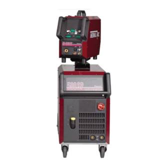
320SP 400SP POWERMASTER 500SP Art # A-07718 Operator Manual Version No: AD Issue Date: March 16, 2007 Manual No.: 0-4968 Operating Features: PHASE... - Page 2 WE APPRECIATE YOUR BUSINESS! Congratulations on your new Thermal Arc product. We are proud to have you as our customer and will strive to provide you with the best service and reliability in the industry. This product is backed by our extensive warranty and world-wide service network.
- Page 3 While the information contained in this Manual represents the Manufacturer's best judgement, the Manufacturer assumes no liability for its use. Operator Manual Number 0-4968 for: PowerMaster 320SP Compact W1000102 PowerMaster 400SP with Integrated Water Cooler W1000202 PowerMaster 400SP Compact...
-
Page 4: Table Of Contents
TABLE OF CONTENTS SECTION 1: SAFETY INSTRUCTIONS AND WARNINGS ............1-1 1.01 Arc Welding Hazards ..................1-1 1.02 Principal Safety Standards ................1-4 1.03 Symbol Chart ....................1-5 1.04 Precautions De Securite En Soudage A L’arc ..........1-6 1.05 Dangers relatifs au soudage à l’arc ..............1-6 1.06 Principales Normes De Securite .............. - Page 5 TABLE OF CONTENTS TABLE OF CONTENTS (continued) SECTION 5: MANUAL GMAW WELDING ................ 5-1 5.01 Types of Weld Transfer Modes ............... 5-1 5.02 Holding and Manipulating the Torch ............... 5-2 5.03 Basics of Pulsed Arc Welding ................. 5-4 5.04 Pulsed Arc Welding Parameters ..............5-5 5.05 Smart, Pulse or TwinPulse GMAW Welding ............
-
Page 7: Safety Instructions And Warnings
POWERMASTER 320SP, 400SP, 500SP SECTION 1: SAFETY INSTRUCTIONS AND WARNINGS WARNING PROTECT YOURSELF AND OTHERS FROM POSSIBLE SERIOUS INJURY OR DEATH. KEEP CHILDREN AWAY. PACEMAKER WEARERS KEEP AWAY UNTIL CONSULTING YOUR DOCTOR. DO NOT LOSE THESE INSTRUCTIONS. READ OPERATING/INSTRUCTION MANUAL BEFORE INSTALLING, OPERATING OR SERVICING THIS EQUIPMENT. - Page 8 POWERMASTER 320SP, 400SP, 500SP Sparks and spatter fly off from the welding arc. The flying sparks and hot metal, weld spatter, hot workpiece, and hot equipment can cause fires and WARNING burns. Accidental contact of electrode or welding wire to metal objects can cause sparks, overheating, or fire.
- Page 9 POWERMASTER 320SP, 400SP, 500SP 1. Wear approved face shield or safety goggles. Side shields 1. Stop engine before checking or adding fuel. recommended. 2. Do not add fuel while smoking or if unit is near any sparks or 2. Wear proper body protection to protect skin.
-
Page 10: Principal Safety Standards
POWERMASTER 320SP, 400SP, 500SP 1. Do not remove radiator cap when engine is hot. Allow engine 1.02 Principal Safety Standards to cool. Safety in Welding and Cutting, ANSI Standard Z49.1, from 2. Wear gloves and put a rag over cap area when removing cap. -
Page 11: Symbol Chart
POWERMASTER 320SP, 400SP, 500SP 1.03 Symbol Chart Note that only some of these symbols will appear on your model. Wire Feed Function Single Phase Wire Feed Towards Workpiece With Three Phase Output Voltage Off. Three Phase Static Frequency Converter- Welding Gun... -
Page 12: Precautions De Securite En Soudage A L'arc
POWERMASTER 320SP, 400SP, 500SP 1.04 Precautions De Securite En Soudage A L’arc MISE EN GARDE LE SOUDAGE A L’ARC EST DANGEREUX PROTEGEZ-VOUS, AINSI QUE LES AUTRES, CONTRE LES BLESSURES GRAVES POSSIBLES OU LA MORT. NE LAISSEZ PAS LES ENFANTS S’APPROCHER, NI LES PORTEURS DE STIMULATEUR CARDIAQUE (A MOINS QU’ILS N’AIENT CONSULTE UN MEDECIN). - Page 13 POWERMASTER 320SP, 400SP, 500SP AVERTISSEMENT AVERTISSEMENT LES VAPEURS ET LES FUMEES SONT LE RAYONNEMENT DE L’ARC PEUT BRÛLER LES DANGEREUSES POUR LA SANTE. YEUX ET LA PEAU; LE BRUIT PEUT ENDOMMAGER L’OUIE. Le soudage dégage des vapeurs et des fumées dangereuses à...
- Page 14 POWERMASTER 320SP, 400SP, 500SP 7. Ne soudez des tôles galvanisées ou plaquées au plomb ou 1. Portez un écran facial ou des lunettes protectrices au cadmium que si les zones à souder ont été grattées à approuvées. Des écrans latéraux sont recommandés.
-
Page 15: Principales Normes De Securite
POWERMASTER 320SP, 400SP, 500SP 1. Portez toujours un écran facial en travaillant sur un accumu- lateur. AVERTISSEMENT 2. Arrêtez le moteur avant de connecter ou de déconnecter des câbles d’accumulateur. LE CARBURANT PEUR CAUSER UN INCENDIE OU 3. N’utilisez que des outils anti-étincelles pour travailler sur un UNE EXPLOSION. -
Page 16: Graphique De Symbole
POWERMASTER 320SP, 400SP, 500SP 1.07 Graphique de Symbole Seulement certains de ces symboles apparaîtront sur votre modèle. Déroulement du Fil Sous Tension Mono Phasé Alimentation du Fil Vers la Pièce de Fabrication Hors Tension Trois Phasé Hors Tension Tri-Phase Statique... -
Page 17: Introduction
Electronic copies of this manual can also be down- loaded at no charge in Acrobat PDF format by going to the Thermal Arc web site listed below and clicking on the Literature Library link: http://www.thermalarc.com March 16, 2007... -
Page 18: Machine Components (500Sp, 400Sp, And Sp4000W)
POWERMASTER 320SP, 400SP, 500SP 2.04 Machine Components (500SP, 400SP, and SP4000W) (10) (11) (17) (12) (13) (16) (14) (15) Art # A-07717 10. Handle 1. External Wire Feeder (N/A with compact models) 11. Mains On/Off Switch 2. Protective Cover, Operation Panel 3. -
Page 19: Machine Components (400Sp Compact Model)
POWERMASTER 320SP, 400SP, 500SP 2.05 Machine Components (400SP Compact Model) (10) (12) (15) (11) Art # A-07884 9. Mains On/Off Switch 1. Wire Feeder Door Panel 10. Air intake 2. Protective Cover, Operation Panel 11. Positive Connection Socket for Work Lead 3. -
Page 20: Machine Components (320Sp Compact Model)
POWERMASTER 320SP, 400SP, 500SP 2.06 Machine Components (320SP Compact Model) (2), (10) Art # A-07908 (13) (14) 1. Wire Feeder Door Panel 9. MIG Torch Connection 2. Carrying Handle 10. Lifting Point (refer to Section 2.07) 3. Protective Cover, Operation Panel 11. -
Page 21: Lifting Points
POWERMASTER 320SP, 400SP, 500SP 2.07 Lifting Points Maximum Art # A-07909 Lifting Point for 320SP and 400SP Compact Art # A-07910 Lifting Points for 500SP and 400SP March 16, 2007... -
Page 22: Power Supply Specifications (Part 1)
POWERMASTER 320SP, 400SP, 500SP 2.08 Power Supply Specifications (part 1) PowerMaster Power Source Part Numbers 320SP 400SP 500SP Compact Power Supply with Integrated Wirefeeder W1000102 W1000304 Remote Power Supply with Integrated Torch Water Cooling System W1000202 W1000502 Automation Power Supply with Integrated Torch Water Cooling System... -
Page 23: Power Supply Specifications (Part 2)
POWERMASTER 320SP, 400SP, 500SP 2.09 Power Supply Specifications (part 2) Electrical Specifications for SMAW / STICK with Three-Phase Input Power Welding Output 320SP 400SP 500SP Duty Cycle 100% 3 Phase Duty Cycle 60% 3 Phase Duty Cycle at Maximum Current 3 Phase 50%@380A, 35.2V 60%@480A, 39.2V... -
Page 24: Wire Feeder Specifications
POWERMASTER 320SP, 400SP, 500SP 2.10 Wire Feeder Specifications Wirefeeder Part Numbers SP4000W SP4000R Wirefeeder suits water cooled torch W3000102 – Wirefeeder suits Automation Power Source – W3000302 Welding Output Weldable Wire Steel & Stainless Steel Ø in .023 – .045 .023 –... -
Page 25: Features And Benefits Common To All Powermaster Sp Systems
POWERMASTER 320SP, 400SP, 500SP 2.11 Features and Benefits Common to all PowerMaster SP Systems # SOFTWARE (Standard) HARDWARE (Standard) Links the wire feed speed, arc current Inverter Design: Heavy duty, highly efficient, and voltage to deliver the perfect welding parameters... -
Page 26: Features And Benefits Common To All Powermaster Sp Systems (Con't)
POWERMASTER 320SP, 400SP, 500SP 2.11 Features and Benefits Common to all PowerMaster SP Systems (con't) # PERFORMANCE (Standard) HARDWARE/SOFTWARE (Options) Operating Platform: How would you like to use the High Speed Pulse is specialized high speed machine? What is your primary parameter is it Inches wave design for maximum productivity. -
Page 27: Installation
10°. Only transport or position the machine for welding on a flat and level surface. Thermal Arc advises that a suitable Mains Plug and cable be fitted to this equipment by a qualified electrical trades-person. -
Page 28: Voltage Change-Over
POWERMASTER 320SP, 400SP, 500SP WARNING WARNING ELECTRIC SHOCK CAN KILL. The mains cable has to be assembled into Open the main wall disconnect switch or the cable gland as shown in the picture. breaker, before removing any covers or The electrical technician has to make sure access panels on the welding machine. -
Page 29: Connecting 3-Phase Input Power To 400Sp Or 500Sp
POWERMASTER 320SP, 400SP, 500SP 3.05 Connecting 3-Phase Input Power to 400SP or 500SP WARNINGS Installation must meet all National and Local Codes - have only qualified persons make this installation. Disconnect and lockout/tagout input power before connecting input conductors from unit. - Page 30 POWERMASTER 320SP, 400SP, 500SP WARNING Never connect the safety ground screw to one of the three line phases. This would represent a serious electrical shock hazard. The wiring to this machine should be performed by a qualified person only. A. Input Power Conductors (Customer Supplied Cord) Select size of conductors using table.
-
Page 31: Connecting Single-Phase Input Power To 320Sp Or 400Sp Or 500Sp
POWERMASTER 320SP, 400SP, 500SP 3.06 Connecting Single-Phase Input Power to 320SP or 400SP or 500SP WARNINGS Installation must meet all National and Local Codes - have only qualified persons make this instal- lation. Disconnect and lockout/tagout input power before connecting input conductors from unit. - Page 32 POWERMASTER 320SP, 400SP, 500SP F. Select type and size of over-current protection using table (fused Line Disconnect Switch shown). WARNING G. Close and secure door on Line Disconnect Switch. Never connect the safety ground screw to H. Remove lockout/tagout device, and place switch one of the three line phases.
-
Page 33: Quick Start Set Up
WARNING 3. Locate the thumbscrew on the gun adapter inside the unit. Loosen the thumbscrew and Thermal Arc advises that a suitable Mains insert the gun cable end into the gun adapter Plug be fitted to this equipment by a as far as it will go. - Page 34 POWERMASTER 320SP, 400SP, 500SP B. How To Connect The Work lead E. How To Install The Wire Spool Connect the Work Lead to the Negative Connection Open the wire feed compartment lid on the power and fasten it by turning the connector to the right.
- Page 35 POWERMASTER 320SP, 400SP, 500SP F. Insertion Of The Wire Electrode Press the inch switch button until the wire appears approximately 3/4 in. (20 mm) out of the Screw out the contact tip in the MIG torch handset. torch neck. Open the wire feed compartment lid on the power supply or wirefeed case.
- Page 36 POWERMASTER 320SP, 400SP, 500SP H. How To Refill The Cooling Fluid How To Configure The Power Supply For Aluminum Welding Only use original MIG/TIG coolant for refill. It provides protection against frost down to 4°F Change the feedrolls to U groove for aluminum wire (-20°C).
-
Page 37: Tweco Pulsemaster Pma5512 500 Amp Weld Gun
TWECO Pulsemaster MIG guns may be fitted to many different types of MIG welding Power Supplies so that your whole shop can be converted to TWECO Pulsemaster. Not only will this give greater reliability (and hence greater productivity) but it will reduce stockholding of consumable parts. See your Thermal Arc distributor for details. -
Page 38: Installing A New Wire Conduit
POWERMASTER 320SP, 400SP, 500SP 3.10 Installing A New Wire Conduit NOTE When the conduit is fully inserted into the 1. Be sure the MIG gun cable is arranged in a straight cable assembly and the conduit stop is line, free from twists, when installing or remov- firmly against the Connector Plug, the “raw... -
Page 39: Operation
POWERMASTER 320SP, 400SP, 500SP SECTION 4: OPERATION 4.01 General Safety Precautions Read and understand the safety instructions at the beginning of this manual prior to operating this machine. WARNING: Be sure to put on proper protective clothing and eye safeguards (welding coat, apron, gloves, and welding helmet, with proper lenses installed). -
Page 40: Welding Controls
POWERMASTER 320SP, 400SP, 500SP (46) ”Welding wire diameter” push-button For diameter selection of the wire to be welded. The push-button is also used for the “End” function, with which you can move back 4.02 Welding Controls to the previous menu level. - Page 41 POWERMASTER 320SP, 400SP, 500SP (55) “Primary parameter” indicator lights These lights show which primary parameter is currently displayed in the multifunction display (54). (56) “Primary parameter” push-button For switching between welding current, material thickness, wire feed speed and arc length, as indicated in the digital multifunction display (54).
-
Page 42: Menu Structure
POWERMASTER 320SP, 400SP, 500SP 4.03 Menu Structure Main Menu Level 1 “Extras” Level 2 Remark Gas pre-flow 0 – 10 sec.; not in SMAW/STICK electrode process Start current 20 % – 200 % of the welding current Start current time 0 –... -
Page 43: Main Menu
POWERMASTER 320SP, 400SP, 500SP Level 1 Main Menu “Extras” Level 2 Enter menu item by pressing both keys (51) at the same time Gas pre - flow 1 Machine data Operating system Master Start current Operating system Process Change between... - Page 44 POWERMASTER 320SP, 400SP, 500SP b. Press the “TT Save” button (45) (Save LED flashes). c. Select the target job number with the push- buttons (44) (-) and (48) (+) or with the smart A. Secondary Parameters (Menu Main torch rocker, and confirm with the “TT Enter”...
- Page 45 POWERMASTER 320SP, 400SP, 500SP 5. Re-saving/Re-programming jobs: a. Switch the Tiptronic function on by pressing “Tiptronic” (49) and select a job (see Selecting Jobs). f. The edit mode is ended by pressing b. Change the settings as required. pushbutton (46) (END) or by pressing the push-buttons (51) at the same time.
-
Page 46: Special Functions
POWERMASTER 320SP, 400SP, 500SP D. Code lock function The lock function in menu Extras is secured with a code lock. A three-digit code must be entered before the lock function can be changed. Only after the 4.04 Special functions correct code is entered, the lock function can be altered. -
Page 47: Smart Gmaw, Pulse Gmaw & Twinpulse Programs
POWERMASTER 320SP, 400SP, 500SP 4.05 Smart GMAW, Pulse GMAW & TwinPulse Programs Material Shield Wire Program Smart GMAW Pulse GMAW TwinPulse size Number Current Range Current Range Current Range Type Name Ar / CO2 / O2 / He max min... -
Page 48: Welding Setting Selection Guide
POWERMASTER 320SP, 400SP, 500SP 4.06 Welding Setting Selection Guide Base Material Thickness Guide Wire Gas Combinations 320SP 400SP 500SP Decimal Fraction Gauge Decimal Synergic Synergic Synergic Pulse Pulse Pulse Material Shield Smart Smart Smart Steel &Twin &Twin &Twin Thickness Thickness... - Page 49 POWERMASTER 320SP, 400SP, 500SP Three Steps To GMAW (MIG) Welding 1.Set Variables A) Select Process : MANUAL GMAW SMART GMAW PULSE GMAW TWIN PULSE B) Select Wire Type C) Select Wire Size D) Select Shielding Gas 2.Set Function E) Set Trigger to 2T or 4T.
- Page 50 POWERMASTER 320SP, 400SP, 500SP March 16, 2007 4-12...
-
Page 51: Manual Gmaw Welding
POWERMASTER 320SP, 400SP, 500SP SECTION 5: MANUAL GMAW WELDING E. Working range at GMAW welding 5.01 Types of Weld Transfer Modes A. Dip transfer mode (short circuit arc) Wire Long arc / Transitional Short circuit This type of arc is especially suitable for thin materials... -
Page 52: Holding And Manipulating The Torch
POWERMASTER 320SP, 400SP, 500SP 5.02 Holding and Manipulating the A. Length of the arc Torch Welding with a longer arc reduces the penetration, the welding bead is wide and flat with increased NOTE spattering. The welding material is transferred with slightly larger drops than welding with a shorter arc. - Page 53 POWERMASTER 320SP, 400SP, 500SP C. Material Transfer Art # A-06384 Benefits: • Controlled, short-circuit-proof material transfer without spatter • Low thermal transfer due to low primary current Disadvantages: • Only shielding gases with low CO2 content can be used March 16, 2007...
-
Page 54: Basics Of Pulsed Arc Welding
POWERMASTER 320SP, 400SP, 500SP 5.03 Basics of Pulsed Arc Welding A. Current and voltage pulses Material transfer is achieved by current and voltage pulses controlled at the same rate as the pulse frequency. The arc power is changed by the ratio between background and pulses current, the pulse duty cycle and the pulse frequency. -
Page 55: Pulsed Arc Welding Parameters
POWERMASTER 320SP, 400SP, 500SP 5.04 Pulsed Arc Welding Parameters increasing the primary current and reducing the pulse current at the same time. Remember that excessively A. Pulse period t high primary current will melt the free wire end too quickly. This will form very large drops which can... -
Page 56: Smart, Pulse Or Twinpulse Gmaw Welding
POWERMASTER 320SP, 400SP, 500SP 5.05 Smart, Pulse or TwinPulse 5.06 Conventional Manual GMAW/ GMAW Welding FCAW Welding The following instructions explain how to set up for The following instructions explain how to set up for SmartGMAW or PulseGMAW or TwinPulse welding. -
Page 57: Smaw/Stick Welding
POWERMASTER 320SP, 400SP, 500SP 5.07 SMAW/STICK Welding The following instructions explain how to set up for SMAW/STICK welding. Art # A-07869 Tiptronic S ave Enter TT S auver TT Entrer SMAW/STICK (END) (+ ) Processus (FIN) Enter Entrer Process Art # A-07872... - Page 58 POWERMASTER 320SP, 400SP, 500SP March 16, 2007...
-
Page 59: Service
POWERMASTER 320SP, 400SP, 500SP SECTION 6: SERVICE 6.01 Maintenance Maintain more often Warning! if used under severe Disconnect input power before maintaining. conditions Each Use Visual check of torch Visual check of electrode and shield cup regulator and pressure Weekly... -
Page 60: System Troubleshooting Guide
POWERMASTER 320SP, 400SP, 500SP 6.02 System Troubleshooting Guide Symptom Cause Remedy Torch too hot Insufficient coolant through flow due to pollution in Flush the coolant hoses of the torch in opposite coolant direction Contact tip is not tight or the wrong size for the wire... -
Page 61: Welding Process Troubleshooting Guide
POWERMASTER 320SP, 400SP, 500SP 6.03 Welding Process Troubleshooting Guide Symptom Cause Remedy Poor edge wetting on Gas mixture in the cylinder has separated due to lack Place protective cap used for storage and stainless steel welds of use transport on cylinder then carefully disconnect the cylinder from the welder and lay it down on the floor. -
Page 62: Error Codes
Mains voltage too high (24V supply > 36V) Check mains voltage and control transformer (*2) Secondary over-current Welding current is too high Notify an accredited Thermal Arc Service Provider for repair Air cooling error Temperature sensor of the power unit Check fans and their wiring... -
Page 63: Appendix 1: Optional Accessories And Consumables
POWERMASTER 320SP, 400SP, 500SP APPENDIX 1: OPTIONAL ACCESSORIES AND CONSUMABLES Wirefeeders Part No. Feature SP4000W W3000202 Water cooled connections, 4 Roll, suits 400SP/500SP SP4000R W3000302 Water cooled connections, 4 Roll suits 400SP/500SP Automation MIG Guns Part No. Feature PulseMaster 12ft Smart Gun PMA512S-3545 Built in Remote Controls. -
Page 64: Appendix 2: Feed Roll Information
POWERMASTER 320SP, 400SP, 500SP APPENDIX 2: FEED ROLL INFORMATION DRIVE ROLL KITS – 4 ROLLS Description Style 1 Style 2 Style 3 Provides less wire friction in the MIG torch due to the straightening effect of the feed rolls system,... -
Page 65: Appendix 3: Mounting The Torch Holder
POWERMASTER 320SP, 400SP, 500SP APPENDIX 3: MOUNTING THE TORCH HOLDER Art # A-07728 March 16, 2007... -
Page 66: Limited Warranty
No employee, agent, or representative of Thermal Arc is authorized to change this warranty in any way or grant any other warranty, and Thermal Arc shall not be bound by any such attempt. -
Page 67: Warranty Schedule
WARRANTY SCHEDULE This information applies to Thermal Arc products that were purchased in the USA and Canada. April 2006 ENGINE DRIVEN WELDERS ARRANTY ERIOD ABOR Scout, Raider, Explorer Original Main Power Stators and Inductors ..................3 years 3 years Original Main Power Rectifiers, Control P.C. -
Page 69: Global Customer Service Contact Information
GLOBAL CUSTOMER SERVICE CONTACT INFORMATION Thermadyne Asia Sdn Bhd Thermadyne USA Lot 151, Jalan Industri 3/5A 2800 Airport Road Rawang Integrated Industrial Park - Jln Batu Arang Denton, Tx 76207 USA 48000 Rawang Selangor Darul Ehsan Telephone: (940) 566-2000 West Malaysia 800-426-1888 Telephone: 603+ 6092 2988 Fax: 800-535-0557... - Page 70 World Headquarters Thermadyne Holdings Corporation Suite 300, 16052 Swingley Ridge Road St. Louis, MO 63017 Telephone: (636) 728-3000 FAX: (636) 728-3010 Email: sales@thermalarc.com www.thermalarc.com...
Need help?
Do you have a question about the POWERMASTER 320SP and is the answer not in the manual?
Questions and answers