
Subscribe to Our Youtube Channel
Related Manuals for Thermal Arc POWERMASTER 320SP


Summary of Contents for Thermal Arc POWERMASTER 320SP
-
Page 1: Service Manual
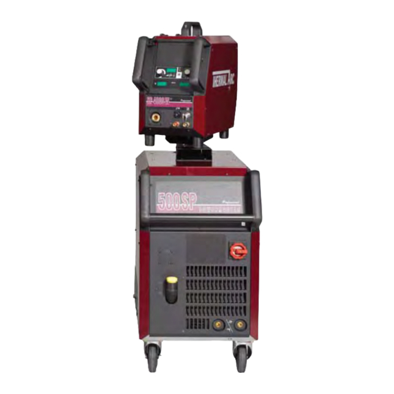
320SP 400SP POWERMASTER 500SP Art # A-07718 Service Manual Revision: AC Issue Date: March 3, 2008 Manual No.: 0-4969 Operating Features: PHASE... - Page 3 PowerMaster 400SP Bw (US) W1000202 PowerMaster 400SP (US) Compact W1000304 PowerMaster 500SP Bw (US) W1000502 Wirefeeder SP4000W Thermal Arc (US) W3000202 Wirefeeder SP4000R Thermal Arc (US) W3000302 Published by: Thermadyne Industries, Inc. 82 Benning Street West Lebanon, New Hampshire, USA 03784 (603) 298-5711 www.thermadyne.com...
-
Page 4: Table Of Contents
TABLE OF CONTENTS TABLE OF CONTENTS (continued) SECTION 1: SAFETY INSTRUCTIONS AND WARNINGS ............1-1 1.01 Arc Welding Hazards ..................1-1 1.02 Principal Safety Standards ................1-4 1.03 Symbol Chart ....................1-5 1.04 Precautions De Securite En Soudage A L’arc ..........1-6 1.05 Dangers relatifs au soudage à... - Page 5 TABLE OF CONTENTS SECTION 5: MANUAL GMAW WELDING ................ 5-1 5.01 Types of Weld Transfer Modes ............... 5-1 5.02 Holding and Manipulating the Torch ............... 5-2 5.03 Basics of Pulsed Arc Welding ................. 5-4 5.04 Pulsed Arc Welding Parameters ..............5-5 5.05 Smart, Pulse or TwinPulse GMAW Welding ............
- Page 6 8.01 Equipment Identification................. 8-1 8.02 How To Use This Parts List ................8-1 8.03 PowerMaster 320SP Exploded View Parts List (1 of 2) ........8-2 8.04 PowerMaster 320SP Exploded View Parts List (2 of 2) ........8-4 8.05 PowerMaster 400SP Compact Exploded View Parts List (1 of 2) ....8-6 8.06 PowerMaster 400SP Compact Exploded View Parts List (2 of 2) ....
- Page 7 TABLE OF CONTENTS APPENDIX 1: OPTIONS AND ACCESSORIES ............A-1 APPENDIX 2: FEED ROLL INFORMATION ............... A-2 APPENDIX 3: MOUNTING THE TORCH HOLDER ............A-3 APPENDIX 4: SP-SERIES BLOCK DIAGRAM ............A-4 APPENDIX 5: POWERMASTER 320P POWER SCHEMATIC ........... A-6 APPENDIX 6: POWERMASTER 400SP POWER SCHEMATIC .........
-
Page 9: Safety Instructions And Warnings
POWERMASTER 320SP, 400SP, 500SP SECTION 1: SAFETY INSTRUCTIONS AND WARNINGS WARNING PROTECT YOURSELF AND OTHERS FROM POSSIBLE SERIOUS INJURY OR DEATH. KEEP CHILDREN AWAY. PACEMAKER WEARERS KEEP AWAY UNTIL CONSULTING YOUR DOCTOR. DO NOT LOSE THESE INSTRUCTIONS. READ OPERATING/INSTRUCTION MANUAL BEFORE INSTALLING, OPERATING OR SERVICING THIS EQUIPMENT. - Page 10 POWERMASTER 320SP, 400SP, 500SP Sparks and spatter fly off from the welding arc. The flying sparks and hot metal, weld spatter, hot workpiece, and hot equipment can cause fires and WARNING burns. Accidental contact of electrode or welding wire to metal objects can cause sparks, overheating, or fire.
- Page 11 POWERMASTER 320SP, 400SP, 500SP 1. Wear approved face shield or safety goggles. Side shields 1. Stop engine before checking or adding fuel. recommended. 2. Do not add fuel while smoking or if unit is near any sparks or 2. Wear proper body protection to protect skin.
-
Page 12: Principal Safety Standards
POWERMASTER 320SP, 400SP, 500SP 1. Do not remove radiator cap when engine is hot. Allow engine 1.02 Principal Safety Standards to cool. Safety in Welding and Cutting, ANSI Standard Z49.1, from 2. Wear gloves and put a rag over cap area when removing cap. -
Page 13: Symbol Chart
POWERMASTER 320SP, 400SP, 500SP 1.03 Symbol Chart Note that only some of these symbols will appear on your model. March 3, 2008... -
Page 14: Precautions De Securite En Soudage A L'arc
POWERMASTER 320SP, 400SP, 500SP 1.04 Precautions De Securite En Soudage A L’arc MISE EN GARDE LE SOUDAGE A L’ARC EST DANGEREUX PROTEGEZ-VOUS, AINSI QUE LES AUTRES, CONTRE LES BLESSURES GRAVES POSSIBLES OU LA MORT. NE LAISSEZ PAS LES ENFANTS S’APPROCHER, NI LES PORTEURS DE STIMULATEUR CARDIAQUE (A MOINS QU’ILS N’AIENT CONSULTE UN MEDECIN). - Page 15 POWERMASTER 320SP, 400SP, 500SP AVERTISSEMENT AVERTISSEMENT LES VAPEURS ET LES FUMEES SONT LE RAYONNEMENT DE L’ARC PEUT BRÛLER LES DANGEREUSES POUR LA SANTE. YEUX ET LA PEAU; LE BRUIT PEUT ENDOMMAGER L’OUIE. Le soudage dégage des vapeurs et des fumées dangereuses à...
- Page 16 POWERMASTER 320SP, 400SP, 500SP 7. Ne soudez des tôles galvanisées ou plaquées au plomb ou 1. Portez un écran facial ou des lunettes protectrices au cadmium que si les zones à souder ont été grattées à approuvées. Des écrans latéraux sont recommandés.
-
Page 17: Principales Normes De Securite
POWERMASTER 320SP, 400SP, 500SP 1. Portez toujours un écran facial en travaillant sur un accumu- lateur. AVERTISSEMENT 2. Arrêtez le moteur avant de connecter ou de déconnecter des câbles d’accumulateur. LE CARBURANT PEUR CAUSER UN INCENDIE OU 3. N’utilisez que des outils anti-étincelles pour travailler sur un UNE EXPLOSION. -
Page 18: Graphique De Symbole
POWERMASTER 320SP, 400SP, 500SP 1.07 Graphique de Symbole Seulement certains de ces symboles apparaîtront sur votre modèle. Déroulement du Fil Sous Tension Mono Phasé Alimentation du Fil Vers la Pièce de Fabrication Hors Tension Trois Phasé Hors Tension Tri-Phase Statique... -
Page 19: Introduction
Electronic copies of this manual can also be down- loaded at no charge in Acrobat PDF format by going to the Thermal Arc web site listed below and clicking on the Literature Library link: http://www.thermalarc.com March 3, 2008... -
Page 20: Machine Components (500Sp, 400Sp, And Sp4000W)
POWERMASTER 320SP, 400SP, 500SP 2.04 Machine Components (500SP, 400SP, and SP4000W) (10) (11) (17) (12) (13) (16) (14) (15) Art # A-07717 10. Handle 1. External Wire Feeder (N/A with compact models) 2. Protective Cover, Operation Panel 11. Mains On/Off Switch 12. -
Page 21: Machine Components (400Sp Compact Model)
POWERMASTER 320SP, 400SP, 500SP 2.05 Machine Components (400SP Compact Model) (10) (12) (15) (11) Art # A-07884 9. Mains On/Off Switch 1. Wire Feeder Door Panel 10. Air intake 2. Protective Cover, Operation Panel 11. Positive Connection Socket for Work Lead 3. -
Page 22: Machine Components (320Sp Compact Model)
POWERMASTER 320SP, 400SP, 500SP 2.06 Machine Components (320SP Compact Model) (2), (10) Art # A-07908 (13) (14) 1. Wire Feeder Door Panel 9. MIG Torch Connection 2. Carrying Handle 10. Lifting Point (refer to Section 2.07) 3. Protective Cover, Operation Panel 11. -
Page 23: Lifting Points
POWERMASTER 320SP, 400SP, 500SP 2.07 Lifting Points Maximum Art # A-07909 Art # A-07910 Lifting Point for 320SP and 400SP Compact Lifting Points for 500SP and 400SP March 3, 2008... -
Page 24: Power Supply Specifications (Part 1)
POWERMASTER 320SP, 400SP, 500SP 2.08 Power Supply Specifications (part 1) PowerMaster Power Source Part Numbers 320SP 400SP 500SP Compact Power Supply with Integrated Wirefeeder W1000102 W1000304 Remote Power Supply with Integrated Torch Water Cooling System W1000202 W1000502 Automation Power Supply with Integrated Torch Water Cooling System... -
Page 25: Power Supply Specifications (Part 2)
POWERMASTER 320SP, 400SP, 500SP 2.09 Power Supply Specifications (part 2) Electrical Specifications for SMAW / STICK with Three-Phase Input Power Welding Output 320SP 400SP 500SP Duty Cycle 100% 3 Phase Duty Cycle 60% 3 Phase Duty Cycle at Maximum Current 3 Phase 50%@380A, 35.2V 60%@480A, 39.2V... -
Page 26: Wire Feeder Specifications
POWERMASTER 320SP, 400SP, 500SP 2.10 Wire Feeder Specifications Wirefeeder Part Numbers SP4000W SP4000R Wirefeeder suits water cooled torch W3000102 – Wirefeeder suits Automation Power Source – W3000302 Welding Output Weldable Wire Steel & Stainless Steel Ø in .023 – .045 .023 –... -
Page 27: Features And Benefits Common To All Powermaster Sp Systems
POWERMASTER 320SP, 400SP, 500SP 2.11 Features and Benefits Common to all PowerMaster SP Systems # SOFTWARE (Standard) HARDWARE (Standard) Links the wire feed speed, arc current Inverter Design: Heavy duty, highly efficient, and voltage to deliver the perfect welding parameters... - Page 28 POWERMASTER 320SP, 400SP, 500SP 2.11 Features and Benefits Common to all PowerMaster SP Systems (con't) # PERFORMANCE (Standard) HARDWARE/SOFTWARE (Options) Operating Platform: How would you like to use the High Speed Pulse is specialized high speed machine? What is your primary parameter is it Inches wave design for maximum productivity.
-
Page 29: Installation
10°. Only transport or position the machine for welding on a flat and level surface. Thermal Arc advises that a suitable Mains Plug and cable be fitted to this equipment by a qualified electrical trades-person. -
Page 30: Voltage Change-Over
POWERMASTER 320SP, 400SP, 500SP WARNING WARNING ELECTRIC SHOCK CAN KILL. The mains cable has to be assembled into Open the main wall disconnect switch or the cable gland as shown in the picture. breaker, before removing any covers or The electrical technician has to make sure access panels on the welding machine. -
Page 31: Connecting 3-Phase Input Power To 400Sp Or 500Sp
POWERMASTER 320SP, 400SP, 500SP 3.05 Connecting 3-Phase Input Power to 400SP or 500SP WARNINGS Installation must meet all National and Local Codes - have only qualified persons make this installation. Disconnect and lockout/tagout input power before connecting input conductors from unit. - Page 32 POWERMASTER 320SP, 400SP, 500SP WARNING Never connect the safety ground screw to one of the three line phases. This would represent a serious electrical shock hazard. The wiring to this machine should be performed by a qualified person only. A. Input Power Conductors (Customer Supplied Cord) Select size of conductors using table.
-
Page 33: Connecting Single-Phase Input Power To 320Sp Or 400Sp Or 500Sp
POWERMASTER 320SP, 400SP, 500SP 3.06 Connecting Single-Phase Input Power to 320SP or 400SP or 500SP WARNINGS Installation must meet all National and Local Codes - have only qualified persons make this instal- lation. Disconnect and lockout/tagout input power before connecting input conductors from unit. - Page 34 POWERMASTER 320SP, 400SP, 500SP F. Select type and size of over-current protection using table (fused Line Disconnect Switch shown). WARNING G. Close and secure door on Line Disconnect Switch. Never connect the safety ground screw to H. Remove lockout/tagout device, and place switch one of the three line phases.
-
Page 35: Section
WARNING 3. Locate the thumbscrew on the gun adapter inside the unit. Loosen the thumbscrew and Thermal Arc advises that a suitable Mains insert the gun cable end into the gun adapter Plug be fitted to this equipment by a as far as it will go. - Page 36 POWERMASTER 320SP, 400SP, 500SP B. How To Connect The Work lead E. How To Install The Wire Spool Connect the Work Lead to the Negative Connection Open the wire feed compartment lid on the power and fasten it by turning the connector to the right.
- Page 37 POWERMASTER 320SP, 400SP, 500SP F. Insertion Of The Wire Electrode Press the inch switch button until the wire appears approximately 3/4 in. (20 mm) out of the Screw out the contact tip in the MIG torch handset. torch neck. Open the wire feed compartment lid on the power supply or wire feed case.
- Page 38 POWERMASTER 320SP, 400SP, 500SP H. How To Refill The Cooling Fluid How To Configure The Power Supply For Aluminum Welding Only use original MIG/TIG coolant for refill. It provides protection against frost down to 4°F Change the feedrolls to U groove for aluminum wire (-20°C).
-
Page 39: Tweco Pulsemaster Pma5512 500 Amp Weld Gun
TWECO Pulsemaster MIG guns may be fitted to many different types of MIG welding Power Supplies so that your whole shop can be converted to TWECO Pulsemaster. Not only will this give greater reliability (and hence greater productivity) but it will reduce stockholding of consumable parts. See your Thermal Arc distributor for details. -
Page 40: Installing A New Wire Conduit
POWERMASTER 320SP, 400SP, 500SP NOTE 3.10 Installing A New Wire Conduit When the conduit is fully inserted into the 1. Be sure the MIG gun cable is arranged in a straight cable assembly and the conduit stop is line, free from twists, when installing or remov- firmly against the Connector Plug, the “raw... -
Page 41: Operation
POWERMASTER 320SP, 400SP, 500SP SECTION 4: OPERATION 4.01 General Safety Precautions Read and understand the safety instructions at the beginning of this manual prior to operating this machine. WARNING: Be sure to put on proper protective clothing and eye safeguards (welding coat, apron, gloves, and welding helmet, with proper lenses installed). -
Page 42: Welding Controls
POWERMASTER 320SP, 400SP, 500SP (46) ”Welding wire diameter” push-button For diameter selection of the wire to be welded. The push-button is also used for the “End” function, with which you can move back 4.02 Welding Controls to the previous menu level. - Page 43 POWERMASTER 320SP, 400SP, 500SP (55) “Primary parameter” indicator lights These lights show which primary parameter is currently displayed in the multifunction display (54). (56) “Primary parameter” push-button For switching between welding current, material thickness, wire feed speed and arc length, as indicated in the digital multifunction display (54).
-
Page 44: Menu Structure
POWERMASTER 320SP, 400SP, 500SP 4.03 Menu Structure Main Menu Level 1 “Extras” Level 2 Remark Gas pre-flow 0 – 10 sec.; not in SMAW/STICK electrode process Start current 20 % – 200 % of the welding current Start current time 0 –... -
Page 45: Main Menu
POWERMASTER 320SP, 400SP, 500SP Level 1 Main Menu “Extras” Level 2 Enter menu item by pressing both keys (51) at the same time Gas pre - flow 1 Machine data Operating system Master Start current Operating system Process Change between... - Page 46 POWERMASTER 320SP, 400SP, 500SP b. Press the “TT Save” button (45) (Save LED flashes). c. Select the target job number with the push- buttons (44) (-) and (48) (+) or with the smart A. Secondary Parameters (Menu Main torch rocker, and confirm with the “TT Enter”...
- Page 47 POWERMASTER 320SP, 400SP, 500SP 5. Re-saving/Reprogramming jobs: a. Switch the Tiptronic function on by pressing “Tiptronic” (49) and select a job (see Selecting Jobs). f. The edit mode is ended by pressing push- b. Change the settings as required. button (46) (END) or by pressing the c.
-
Page 48: Special Functions
POWERMASTER 320SP, 400SP, 500SP current job are reset. All adjustment in the Extras menu (language, display contrast, etc.) remain unchanged. D. Code lock function 4.04 Special functions The lock function in menu Extras is secured with a code lock. A three-digit code must be entered before A. -
Page 49: Smart Gmaw, Pulse Gmaw & Twinpulse Programs
POWERMASTER 320SP, 400SP, 500SP 4.05 Smart GMAW, Pulse GMAW & TwinPulse Programs Material Shield Wire Program Smart GMAW Pulse GMAW TwinPulse size Number Current Range Current Range Current Range Type Name Ar / CO2 / O2 / He max min... -
Page 50: Welding Setting Selection Guide
POWERMASTER 320SP, 400SP, 500SP 4.06 Welding Setting Selection Guide Base Material Thickness Guide Wire Gas Combinations 320SP 400SP 500SP Decimal Fraction Gauge Decimal Synergic Synergic Synergic Pulse Pulse Pulse Material Steel Thickness Thickness Thickness Shield Smart Smart Smart &Twin &Twin &Twin... - Page 51 POWERMASTER 320SP, 400SP, 500SP Three Steps To GMAW (MIG) Welding 1.Set Variables A) Select Process : MANUAL GMAW SMART GMAW PULSE GMAW TWIN PULSE B) Select Wire Type C) Select Wire Size D) Select Shielding Gas 2.Set Function E) Set Trigger to 2T or 4T.
- Page 52 POWERMASTER 320SP, 400SP, 500SP 4-12 March 3, 2008...
-
Page 53: Manual Gmaw Welding
POWERMASTER 320SP, 400SP, 500SP SECTION 5: MANUAL GMAW WELDING E. Working range at GMAW welding 5.01 Types of Weld Transfer Modes A. Dip transfer mode (short circuit arc) Wire Long arc / Transitional Short circuit This type of arc is especially suitable for thin materials... -
Page 54: Holding And Manipulating The Torch
POWERMASTER 320SP, 400SP, 500SP 5.02 Holding and Manipulating the A. Length of the arc Torch Welding with a longer arc reduces the penetration, the welding bead is wide and flat with increased NOTE spattering. The welding material is transferred with slightly larger drops than welding with a shorter arc. - Page 55 POWERMASTER 320SP, 400SP, 500SP C. Material Transfer Art # A-06384 Benefits: • Controlled, short-circuit-proof material transfer without spatter • Low thermal transfer due to low primary current Disadvantages: • Only shielding gases with low CO2 content can be used March 3, 2008...
-
Page 56: Basics Of Pulsed Arc Welding
POWERMASTER 320SP, 400SP, 500SP 5.03 Basics of Pulsed Arc Welding A. Current and voltage pulses Material transfer is achieved by current and voltage pulses controlled at the same rate as the pulse frequency. The arc power is changed by the ratio between background and pulses current, the pulse duty cycle and the pulse frequency. -
Page 57: Pulsed Arc Welding Parameters
POWERMASTER 320SP, 400SP, 500SP 5.04 Pulsed Arc Welding Parameters increasing the primary current and reducing the pulse current at the same time. Remember that excessively A. Pulse period t high primary current will melt the free wire end too quickly. This will form very large drops which can... -
Page 58: Smart, Pulse Or Twinpulse Gmaw Welding
POWERMASTER 320SP, 400SP, 500SP 5.05 Smart, Pulse or TwinPulse 5.06 Conventional Manual GMAW/ GMAW Welding FCAW Welding The following instructions explain how to set up for The following instructions explain how to set up for SmartGMAW or PulseGMAW or TwinPulse welding. -
Page 59: Smaw/Stick Welding
POWERMASTER 320SP, 400SP, 500SP 5.07 SMAW/STICK Welding The following instructions explain how to set up for SMAW/STICK welding. Art # A-07869 Tiptronic S ave Enter TT S auver TT Entrer SMAW/STICK (END) (+ ) Processus (FIN) Enter Entrer Process Art # A-07872... - Page 60 POWERMASTER 320SP, 400SP, 500SP March 3, 2008...
-
Page 61: Basic Service
POWERMASTER 320SP, 400SP, 500SP SECTION 6: BASIC SERVICE 6.01 Maintenance Maintain more often Warning! if used under severe Disconnect input power before maintaining. conditions Each Use Visual check of torch Visual check of electrode and shield cup regulator and pressure... -
Page 62: System Troubleshooting Guide
POWERMASTER 320SP, 400SP, 500SP 6.02 System Troubleshooting Guide Symptom Cause Remedy Torch too hot Insufficient coolant through flow due to pollution in Flush the coolant hoses of the torch in opposite coolant direction Contact tip is not tight or the wrong size for the wire... -
Page 63: Welding Process Troubleshooting Guide
POWERMASTER 320SP, 400SP, 500SP 6.03 Welding Process Troubleshooting Guide Symptom Cause Remedy Poor edge wetting on Gas mixture in the cylinder has separated due to lack Place protective cap used for storage and stainless steel welds of use transport on cylinder then carefully disconnect the cylinder from the welder and lay it down on the floor. - Page 64 POWERMASTER 320SP, 400SP, 500SP March 3, 2008...
-
Page 65: Advanced Service
POWERMASTER 320SP, 400SP, 500SP SECTION 7: ADVANCED SERVICE 7.01 Safety Precautions Requirement WARNING: Use and maintenance of welding and cutting machines can be dangerous. Follow the safety precautions in Section 1 of this manual to avoid injuries. Welding and cutting machines must be used by properly trained personnel. -
Page 66: Multivoltage Principle
POWERMASTER 320SP, 400SP, 500SP 7.02 Multivoltage Principle Setting the input switch When switch setting 208V and 230V, the power units are connected parallel. When switch setting 400V and 460V, the power units are connected in series. This applies to either single or 3-phase operation. -
Page 67: Inverter Principle
POWERMASTER 320SP, 400SP, 500SP 7.03 Inverter Principle L1 L2 L3 3 phases 50 Hz mains switch mains filter “soft” power up mains rectifier dc link voltage primary switch clock pulse 80 kHz transformer secondary rectifier Art # A-07732 inductor March 3, 2008... -
Page 68: Common Logic Functions
POWERMASTER 320SP, 400SP, 500SP 7.04 Common Logic Functions Component Function Cause fan (power unit) power module temperature over 40°C power module temperature below 40°C fan (cooling system) after detection “welding current on“ after welding process, two minutes post-cooling time pump after detection “welding current on“... -
Page 69: Error Codes And Troubleshooting Guide
POWERMASTER 320SP, 400SP, 500SP 7.10 Error Codes and Troubleshooting Guide In case of a malfunction, an error code is indicated on the digital multifunction display (54) and the corre- sponding error description appears on the LCD display (50). As long as an error code is indicated, welding operation is not possible. -
Page 70: Flowchart: Soft Power-Up Cycle At Switch On
POWERMASTER 320SP, 400SP, 500SP 7.12 Flowchart: Soft Power-Up Cycle At Switch On NOTE is the bus voltage after the rectifier start Power-ON-Reset finished charge-up and mains relay are off. power units are disabled Error message E17 18V ac from control “operation voltage 18V“... -
Page 71: Power-Up Schematic
POWERMASTER 320SP, 400SP, 500SP 7.13 Power-Up Schematic MVPWRUP MVDRV1 mains RE1-6 input MV-MAPRO +24V RE1-6 Art # A-08391 Control transformer March 3, 2008... -
Page 72: Flowchart: Voltage Monitoring
POWERMASTER 320SP, 400SP, 500SP 7.14 Flowchart: Voltage Monitoring START monitoring input voltage of power unit 1 and 2 error message > 100V “mains undervoltage“ warning > 190V “mains undervoltage“ power unit enable > 380V mains relay on power unit disable... -
Page 73: Monitoring Bus Voltage
POWERMASTER 320SP, 400SP, 500SP 7.15 Monitoring Bus Voltage The bus voltage is monitored by the Process (DSP). The MVDRV is transmitting a certain frequency to the Process (DSP), depending on the bus voltage level. The higher the bus voltage, the higher the frequency. If the bus voltage is too low or too high, the Process (DSP) stops the machine, showing E22 (mains under-voltage) or E23 (mains overvoltage). -
Page 74: Dp-Mapro Pc Board
POWERMASTER 320SP, 400SP, 500SP 7.16 DP-MAPRO PC Board The DP-MAPRO PC board provides the welding sequence and manages the process control of the machine. (MAPRO = MAster-PROcess) Functions • Logic functions of the welding process • generating and monitoring supply voltages •... -
Page 75: Mapro Connector Descriptions & Measuring Points
POWERMASTER 320SP, 400SP, 500SP 7.17 MAPRO Connector Descriptions & Measuring Points connector designation signal interface primary power unit 1 supply primary control DFW1 supply primary control DFW2 supply primary control +15V DC gnd for primary control inverter PWM-low 1 inverter PWM-high 1... - Page 76 POWERMASTER 320SP, 400SP, 500SP connector interpass hose CAN high CAN low supply motor + +70V DC supply motor - separate wire feeder active supply +24V DC supply fan/pump 230V AC from control transformer 230V AC n.c. 230V AC from control transformer...
- Page 77 POWERMASTER 320SP, 400SP, 500SP connector pump / cooling unit supply pump 230V AC supply pump 230V AC only 320SP : supply cooling unit 42V AC only 320SP : supply cooling unit 42V AC CAN Interface 2 supply CAN - supply CAN +...
- Page 78 POWERMASTER 320SP, 400SP, 500SP connector JTAG-Interface TRST/ supply +5V DC n.c. JT TDO JT TCK JT TCK JT_EMU0 JT_EMU1 connector JTAG-Interface supply +3,3V DC n.c. n.c. connector serial interface n.c. n.c. n.c. n.c. connector fan group 2 supply fan 230V AC...
-
Page 79: Mv-Mapro Diagram
POWERMASTER 320SP, 400SP, 500SP 7.18 MV-MAPRO Diagram Art A-08394 DIP Switch Settings If the machine is to be programmed via the serial port, the DIP switches 1-3 has to be set to "ON". In normal operation they has to be set to "OFF". -
Page 80: Dmr Pc Board
POWERMASTER 320SP, 400SP, 500SP 7.19 DMR PC Board The DMR PC board is the wire feed motor control of the machine. Functions • control and monitoring wire feed motor • driving solenoid valve • control and monitoring of operating elements (DS20BF, remote control, torch buttons) •... - Page 81 POWERMASTER 320SP, 400SP, 500SP connector gas valve supply gas valve +24V DC signal gas valve connector Push-Pull supply Push-Pull relais +24V DC supply Push-Pull motor +70V DC signal Push-Pull relais connector interpass hose CAN high CAN low supply motor +70V DC...
-
Page 82: Dmr Diagram
POWERMASTER 320SP, 400SP, 500SP 7.21 DMR Diagram Art # A-08395 March 3, 2008 7-18... -
Page 83: Dmr Schematic
POWERMASTER 320SP, 400SP, 500SP 7.22 DMR Schematic The DMR communicates with the MV-MAPRO via the CAN bus. The microprocessor drives the wire feed motor and monitors the tacho signal of the motor. The monitoring of the tacho signal is enabled via pin 4 of connector X5 (hard-wired in the cable harness). -
Page 84: Ds20Bf Pc Board
POWERMASTER 320SP, 400SP, 500SP 7.23 DS20BF PC Board The DS20BF PC board is the front panel with all buttons, rotary impulse encoder and all displays. Functions • operating/setup the machine • display of all welding parameters • display error messages •... -
Page 85: Mvdrv / Mvmdrv Pc Board
POWERMASTER 320SP, 400SP, 500SP 7.26 MVDRV / MVMDRV PC Board The MVDRV PC board manages the primary drive level of the 400SP and 500SP power units. The MVMDRV PC board manages the primary drive level of the 320SP power unit. - Page 86 POWERMASTER 320SP, 400SP, 500SP Normal MVMRV LED Displays: State Designation 1 (green) supply high side1 ok 2 (green) supply low side1 ok 3 (green) on / off drive level high side1 4 (green) on / off drive level low side1...
-
Page 87: Mvmrv / Mvmdrv Connector Descriptions & Measuring Points
POWERMASTER 320SP, 400SP, 500SP 7.27 MVMRV / MVMDRV Connector Descriptions & Measuring Points Connector Designation Signal interface primary power unit 1 supply primary control DFW1 supply primary control DFW2 supply primary control +15V DC gnd for primary control inverter PWM-low 1... -
Page 88: Mvdrv Schematic
POWERMASTER 320SP, 400SP, 500SP 7.28 MVDRV Schematic Art # A-08398 LED3 driver circuit X1 / 6 high side LED1 supply high side X1 / 1 X1 / 3 LED2 supply X1 / 2 low side LED4 driver circuit X1 / 5 low side 7.29 MVMDRV Schematic... -
Page 89: Mvdrv Diagram
POWERMASTER 320SP, 400SP, 500SP 7.30 MVDRV Diagram Art # A-08400 March 3, 2008 7-25... -
Page 90: Mvmdrv Diagram
POWERMASTER 320SP, 400SP, 500SP 7.31 MVMDRV Diagram Art # A-08401 March 3, 2008 7-26... -
Page 91: Mvpwrup Pc Board
POWERMASTER 320SP, 400SP, 500SP 7.32 MVPWRUP PC Board The MVPWRUP PC board is the power up board of the 320SP, 400SP and 500SP. Functions • reducing start-up peak current for capacitors • supply and safeguarding of control transformer 7.33 MVPWRUP Connector Descriptions & Measuring Points... -
Page 92: Dk-Glcl Pc Board
POWERMASTER 320SP, 400SP, 500SP 7.35 DK-GLCL PC Board The DK-GLCL PC board is for wiring the secondary rectifier diodes. Functions • wiring • pulse smoothing 7.36 DK-GLCL PC Board Diagram Art # A-08403 March 3, 2008 7-28... -
Page 93: Dp-Ufi-Bo Pc Board
POWERMASTER 320SP, 400SP, 500SP 7.37 DP-UFI-BO PC Board Functions • wiring welding sockets • providing output voltage Normal DP-UFI-BO LED Displays: state designation 1 (green) holf-function active connector Designation Signal connector “+“ welding voltage (in MMA mode) + 80V DC “-“... -
Page 94: Dp-Emv Pc Board
POWERMASTER 320SP, 400SP, 500SP 7.39 DP-EMV PC Board Functions - EMC filter 7.40 DP-EMV Connector Descriptions & Measuring Points Connector Designation Signal X2, X3 connector “-“ welding voltage “+“ welding voltage (in MMA mode) +80V DC 7.41 DP-EMV PC Board Diagram... -
Page 95: Ds-Va Pc Board
POWERMASTER 320SP, 400SP, 500SP 7.42 DS-VA PC Board The DS-VA PC board is the digital volt and ampere display. Functions • display nominal and actual values of welding voltage and welding current • hold-function of the last welding values Normal DS-VA LED Displays:... -
Page 96: Current Sensor Vac
POWERMASTER 320SP, 400SP, 500SP 7.46 Current Sensor VAC The current sensor is a 500A sensor with an output ratio of 2000:1 Functions - measuring welding current 7.47 Current Sensor VAC Connector Descriptions & Measuring Points Connector Designation Signal connector supply +... -
Page 97: Control Transformer
POWERMASTER 320SP, 400SP, 500SP 7.49 Control Transformer W7000031 is used in 400SP and 500SP W7000032 is used in 320SP W7000031 W7000032 Art # A-08409 7.50 Measuring Temperature The temperature of the power unit is measured via an NTC resistor. Each heatsink has one NTC resistor: The resistor value of the NTC is 10k ohms at 25°C. -
Page 98: Pcb Connection Diagram
POWERMASTER 320SP, 400SP, 500SP 7.51 PCB Connection Diagram MV-MAPRO Art # A-08410 + 3.3V MVDRV1 + 3.3V MVDRV2 March 3, 2008 7-34... -
Page 99: Supply Voltages
POWERMASTER 320SP, 400SP, 500SP 7.52 Supply Voltages The MV-MAPRO is producing all the necessary supply voltages out of the control transformer. The 19VAC from the control transformer and the +15V DC are monitored by the DSP (Process). The +24V DC and +5V DC are monitored by the Master. -
Page 100: Measuring Welding Current
POWERMASTER 320SP, 400SP, 500SP 7.53 Measuring Welding Current The welding current is measured with the VAC current sensor. It is connected via the MVDRV (400SP and 500SP) or the MVMDRV (320SP) to the MV-MAPRO. The output of the sensor is a current with a ratio of 2000:1. For example: if 100A welding current are flowing, the sensor output would be 50mA. -
Page 101: Measuring Output Voltage
POWERMASTER 320SP, 400SP, 500SP 7.55 Measuring Output Voltage The output voltage is measured by the Master and the Process (DSP) at the same time. The output sockets are wired via the PCB DP-UFI-BO to the MV-MAPRO. MV-MAPRO Art # A-08414... -
Page 102: Encoding Power Units
POWERMASTER 320SP, 400SP, 500SP 7.57 Encoding Power Units During the initialization (switching on the machine), the Process (DSP) is reading the machine configuration and detects what power units are attached to the MV-MAPRO. The type of the power units are set by the DIP switch on the MVDRV 500SP) or MVMDRV boards (320SP). -
Page 103: Parts List
POWERMASTER 320SP, 400SP, 500SP SECTION 8: PARTS LIST 8.01 Equipment Identification All identification numbers as described in the Introduction chapter must be furnished when ordering parts or making inquiries. This information is usually found on the nameplate attached to the equipment. Be sure to include any dash numbers following the Specification or Assembly numbers. -
Page 104: Powermaster 320Sp Exploded View Parts List (1 Of 2)
POWERMASTER 320SP, 400SP, 500SP 8.03 PowerMaster 320SP Exploded View Parts List (1 of 2) Item Description Schematic Ref Part Number Nut,Safety,M12,SP W7004108 Washer,Felt,80x20x4,SP W7004107 Spool Hub,SP W7004106 Shaft,Spool Hub,SP W7004105 Washer,Felt,40x20x4,SP W7004104 Washer,Internal Tab,22,SP W7004103 Spring,21x30,4.25,SP W7004102 Washer,M10x30,SP W7004101 Screw,Cap Head,M10x25,SP W7004100 Handle Tube Top,Ø30x454,320SP... - Page 105 POWERMASTER 320SP, 400SP, 500SP 31 32 Art # A-08261 March 3, 2008...
-
Page 106: Powermaster 320Sp Exploded View Parts List (2 Of 2)
POWERMASTER 320SP, 400SP, 500SP 8.04 PowerMaster 320SP Exploded View Parts List (2 of 2) Item Description Schematic Ref Part Number – – Display Cover Assy,320SP W7000016 Refer to W7000016 #N/A Refer to W7000016 #N/A Terminal Output SP X2, X3 W7000051... - Page 107 POWERMASTER 320SP, 400SP, 500SP Sa ve Sa ve Ente r Ente r Tip tro nic Tip tro nic (END) (END) (+ ) (+ ) Ente r Ente r Mo d e Mo d e HO LD HO LD Art # A-08262...
-
Page 108: Powermaster 400Sp Compact Exploded View Parts List (1 Of 2)
POWERMASTER 320SP, 400SP, 500SP 8.05 PowerMaster 400SP Compact Exploded View Parts List (1 of 2) Item Description Part Number Panel,Side,RH,400SP & 500SP W7004120 Label,Warning,SP W7004116 Label,Mains Connection,Ø30,SP W7004114 PCB Motor Driver,SP W6000006 Spacer,PCB,M4,12mm,SP W7004128 Mat,Rubber,560x350mm,SP W7004122 Display Cover Assy,400SP W7000015... - Page 109 POWERMASTER 320SP, 400SP, 500SP 16 16 Art # A-08265 March 3, 2008...
-
Page 110: Powermaster 400Sp Compact Exploded View Parts List (2 Of 2)
POWERMASTER 320SP, 400SP, 500SP 8.06 PowerMaster 400SP Compact Exploded View Parts List (2 of 2) Item Description Part Number Socket 14Pin Remote RC20 SP W7000053 Socket 4Pin CAN SP W7000052 Cap,CAN Socket,SP W7000096 Chain Gas Cylinder 770mm SP W7000080 Gas Hose,6ft,5/8 18UNF,SP... - Page 111 POWERMASTER 320SP, 400SP, 500SP Art # A-08266 March 3, 2008...
-
Page 112: Powermaster 400Sp Remote, Water Exploded View Parts List
POWERMASTER 320SP, 400SP, 500SP 8.07 PowerMaster 400SP Remote, Water Exploded View Parts List Item Description Part Number Panel,Side,RH,400SP & 500SP W7004120 Panel,Side,LH,400SP & 500SP W7004131 Castor,Swivel,Ø125 SP W7004121 Castor Swivel Brake Ø125 SP W7000084 Wheel Ø200 x 50 SP W7000012... - Page 113 POWERMASTER 320SP, 400SP, 500SP 18 18 24 24 31 31 21 21 33 33 23 23 22 22 36 36 30 30 20 20 28 28 35 35 27 27 29 29 15 15 10 10 25 25 Art # A-08365...
-
Page 114: Powermaster 500Sp Remote, Water Exploded View Parts List
POWERMASTER 320SP, 400SP, 500SP 8.08 PowerMaster 500SP Remote, Water Exploded View Parts List Item Description Part Number Panel,Side,RH,400SP & 500SP W7004120 Panel,Side,LH,400SP & 500SP W7004131 Castor,Swivel,Ø125 SP W7004121 Castor Swivel Brake Ø125 SP W7000084 Wheel Ø200 x 50 SP W7000012... - Page 115 POWERMASTER 320SP, 400SP, 500SP 18 18 24 24 31 31 21 21 33 33 23 23 22 22 36 36 30 30 20 20 28 28 35 35 27 27 29 29 15 15 10 10 25 25 Art # A-08365...
-
Page 116: Powermaster 400Sp Power Module
POWERMASTER 320SP, 400SP, 500SP 8.09 PowerMaster 400SP Power Module Item Description Schematic Ref Part Number PCB Output Diode,SP W6000007 PCB Input Relay, SP W7000026 Fuse 4A 320/400/500SP F4, F5 W6000010 PCB Primary Capacitor 400/500SP W7000027 Inductor 400SP W7000056 Transformer Main 400SP... -
Page 117: Powermaster 500Sp Power Module
POWERMASTER 320SP, 400SP, 500SP 8.10 PowerMaster 500SP Power Module Item Description Schematic Ref Part Number PCB Output Diode,SP W6000007 PCB Input Relay, SP W7000026 Fuse 4A 320/400/500SP F4, F5 W6000010 PCB Primary Capacitor 400/500SP W7000027 Inductor 500SP W7000068 Transformer Main 500SP... -
Page 118: Powermaster Sp Water Cooling System
POWERMASTER 320SP, 400SP, 500SP 8.11 PowerMaster SP Water Cooling System Item Description Part Number Cap Water Tank M33x2,SP W7000014 QuickDisconnect,Blue,Female,SP W7004133 QuickDisconnect,Red,Female,SP W7004134 Radiator,390x130x66,SP W7004136 Tank,Coolant,640 x 80,SP W7004137 Connector,hose,R1/4",SP W7004138 Connector,hose elbow,R1/4",SP W7004139 Flowmeter 400/500SP W6000208 Pump/Motor Coolant 230V,SP... -
Page 119: Powermaster Sp Hr911 Remote Pendant
POWERMASTER 320SP, 400SP, 500SP 8.12 PowerMaster SP HR911 Remote Pendant Item Description Part Number Foot,Rubber,20x10 w/stud,HR911 W7004162 Starlock Cap,Shaft 4mm,HR911 W7004163 Display Cover,HR911,SP W7004167 Refer to W7004167 #N/A Refer to W7004167 #N/A Refer to W7004167 #N/A Strain-Relief,Nut,HR911 W7004168 Refer to W7004167 #N/A Knob,Encoder,.9"Øx1/4"shaft,SP... -
Page 120: Powermaster Sp4000W Wire Feeder (Part 1 Of 2)
POWERMASTER 320SP, 400SP, 500SP 8.13 PowerMaster SP4000W Wire Feeder (part 1 of 2) Item Description Part Number Nut,Safety,M12,SP W7004108 Screw,Cap Head,M10x25,SP W7004100 Washer,M10x30,SP W7004101 Washer,Internal Tab,22,SP W7004103 Holder,MIG Gun,SP W7000086 Panel,Side,RH,SP4000W W7004143 Panel,Door,SP4000W W7004144 Rubber Foot Ø40x46 320SP W7000082 Latch Quarter Turn Ø31 SP... - Page 121 POWERMASTER 320SP, 400SP, 500SP 10 10 45 45 7 13 23 23 Art A-08370 March 3, 2008 8-19...
-
Page 122: Powermaster Sp4000W Wire Feeder (Part 2 Of 2)
POWERMASTER 320SP, 400SP, 500SP 8.13 PowerMaster SP4000W Wire Feeder (part 2 of 2) Item Description Schematic Ref Part Number Knob,Encoder,.9"Øx1/4"shaft,SP W7004164 Cap,Knob,Grey,.9"Ø,SP W7004165 Spring,21x30,4.25,SP W7004102 Insulator Flange Tweco No4 SP W7000021 Rivet Plastic 5x7.5 SP W7000022 Adaptor Tweco No4 SP... - Page 123 POWERMASTER 320SP, 400SP, 500SP 48 48 55 55 1 8 1 2 Sa ve Ente r Tiptronic (END) (+ ) Ente r Mode 5 3 2 6 2 7 4 6 5 2 Art # A-08369 March 3, 2008 8-21...
-
Page 124: Powermaster Sp4000W Feed Plate Assembly
POWERMASTER 320SP, 400SP, 500SP 8.14 PowerMaster SP4000W Feed Plate Assembly Item Description Part Number Feedplate,4R,Mechafin,SP W7004170 Pressure Arm,Right,Mechafin,SP W7004171 Pressure Arm,Left,Mechafin,SP W7004172 Shaft for Feedroll,Mechafin,SP W7004173 Gear,Driveroll,Mechafin,SP W7004174 Drive Gear,Mechafin,SP W7004175 Screw-Washer,Driveroll,M4x6,SP W7004169 Refer to W7004169 #N/A Refer to W7004169... - Page 125 POWERMASTER 320SP, 400SP, 500SP Art # A-08371 March 3, 2008 8-23...
- Page 126 POWERMASTER 320SP, 400SP, 500SP March 3, 2008 8-24...
-
Page 127: Appendix 1: Options And Accessories
POWERMASTER 320SP, 400SP, 500SP APPENDIX 1: OPTIONS AND ACCESSORIES ACCESSORIES Wirefeeders Part No. Feature SP4000W W3000202 Water cooled connections, 4 Roll, suits 400SP/500SP SP4000R W3000302 Water cooled connections, 4 Roll suits 400SP/500SP Automation MIG Guns Part No. Feature PulseMaster 12ft Smart Gun PMA512S-3545 Built in Remote Controls. -
Page 128: Appendix 2: Feed Roll Information
POWERMASTER 320SP, 400SP, 500SP APPENDIX 2: FEED ROLL INFORMATION DRIVE ROLL KITS – 4 ROLLS Description Style 1 Style 2 Style 3 Provides less wire friction in the MIG torch due to the straightening effect of the feed rolls system,... -
Page 129: Appendix 3: Mounting The Torch Holder
POWERMASTER 320SP, 400SP, 500SP APPENDIX 3: MOUNTING THE TORCH HOLDER Art # A-07728 March 3, 2008... -
Page 130: Appendix 4: Sp-Series Block Diagram
POWERMASTER 320SP, 400SP, 500SP APPENDIX 4: SP-SERIES BLOCK DIAGRAM Art # A-07729 March 3, 2008... - Page 131 POWERMASTER 320SP, 400SP, 500SP Art # A-07729 March 3, 2008...
-
Page 132: Appendix 5: Powermaster 320P Power Schematic
POWERMASTER 320SP, 400SP, 500SP APPENDIX 5: POWERMASTER 320P POWER SCHEMATIC PCB4 PCB1 INPUT PCB SWITCHING PCB +UZ1 +UZ1 MAIN RELAYS MAIN RELAYS Primary Line Voltage 208-460 VAC 1PH INRUSH RELAY INRUSH RELAY 4A / 500V -UZ1 -UZ1 MAIN +UZ2 +UZ2... - Page 133 POWERMASTER 320SP, 400SP, 500SP Refer to pages 8-2 and 8-4 for ordering information of parts shown in this schematic. NEG - NEG - FILTER 1 PCB PCB5 PCB7 DP-EMV OCV = 90VDC FILTER 2 PCB PCB6 OUTPUT RECTIFIER PCB Ferrite Rings...
-
Page 134: Appendix 6: Powermaster 400Sp Power Schematic
POWERMASTER 320SP, 400SP, 500SP APPENDIX 6: POWERMASTER 400SP POWER SCHEMATIC PowerMaster 400SP Power Schematic S00.0023.3-00 Art # A-07735_AB March 3, 2008... - Page 135 POWERMASTER 320SP, 400SP, 500SP Refer to pages 8-10 and 8-14 for ordering information of parts shown in this schematic. Art # A-07735_AB March 3, 2008...
-
Page 136: Appendix 7: Powermaster 400Sp Compact Power Schematic
POWERMASTER 320SP, 400SP, 500SP APPENDIX 7: POWERMASTER 400SP COMPACT POWER SCHEMATIC PowerMaster 400SP Compact Power Schematic S00.0023.2-00 Art # A-08553 March 3, 2008 A-10... - Page 137 POWERMASTER 320SP, 400SP, 500SP Refer to pages 8-6, 8-8 and 8-14 for ordering information of parts shown in this schematic. Art # A-08553 March 3, 2008 A-11...
-
Page 138: Appendix 8: Powermaster 500Sp Power Schematic
POWERMASTER 320SP, 400SP, 500SP APPENDIX 8: POWERMASTER 500SP POWER SCHEMATIC PowerMaster 500SP Power Schematic S00.0023.5-00 Art #A-07736_AB March 3, 2008 A-12... - Page 139 POWERMASTER 320SP, 400SP, 500SP Refer to pages 8-12 and 8-15 for ordering information of parts shown in this schematic. Art #A-07736_AB March 3, 2008 A-13...
-
Page 140: Appendix 9: Rectifier Diode Data Sheet
POWERMASTER 320SP, 400SP, 500SP APPENDIX 9: RECTIFIER DIODE DATA SHEET BYT230PIV-1000 BYT231PIV-1000 ® FAST RECOVERY RECTIFIER DIODES MAIN PRODUCT CHARACTERISTICS 2 x 30 A F(AV) 1000 V (max) 1.8 V BYT231PIV-1000 BYT230PIV-1000 trr (max) 80 ns FEATURES AND BENEFITS VERY LOW REVERSE RECOVERY TIME... -
Page 141: Appendix 10: Mosfet Data Sheet
POWERMASTER 320SP, 400SP, 500SP APPENDIX 10: MOSFET DATA SHEET STE53NC50 N-CHANNEL 500V - 0.070Ω - 53A ISOTOP PowerMesh™II MOSFET TYPE DS(on) STE53NC50 500V < 0.08Ω 53 A (on) = 0.07 Ω TYPICAL R EXTREMELY HIGH dv/dt CAPABILITY 100% AVALANCHE TESTED... -
Page 142: Limited Warranty
No employee, agent, or representative of Thermal Arc is authorized to change this warranty in any way or grant any other warranty, and Thermal Arc shall not be bound by any such attempt. Correction of non-conformities, in the manner and time provided herein, constitutes fulfillment of thermal’s obligations to purchaser with respect to the... -
Page 143: Warranty Schedule
WARRANTY SCHEDULE This information applies to Thermal Arc products that were purchased in the USA and Canada. November 2007 SAFETY EQUIPMENT ARRANTY ERIOD ABOR Auto-Darkening Welding Helmet (Electronic Lens) 1 year 1 year Harness Assembly 1 Month 1 Month ENGINE DRIVEN WELDERS... -
Page 145: Global Customer Service Contact Information
GLOBAL CUSTOMER SERVICE CONTACT INFORMATION Thermadyne Asia Sdn Bhd Thermadyne USA 2800 Airport Road Lot 151, Jalan Industri 3/5A Rawang Integrated Industrial Park - Jln Batu Arang Denton, Tx 76207 USA Telephone: (940) 566-2000 48000 Rawang Selangor Darul Ehsan West Malaysia 800-426-1888 Fax: 800-535-0557 Telephone: 603+ 6092 2988... - Page 146 World Headquarters Thermadyne Holdings Corporation Suite 300, 16052 Swingley Ridge Road St. Louis, MO 63017 Telephone: (636) 728-3000 FAX: (636) 728-3010 Email: sales@thermalarc.com www.thermalarc.com...
Need help?
Do you have a question about the POWERMASTER 320SP and is the answer not in the manual?
Questions and answers