Thermal Arc ARCMASTER 300 AC/DC Service Manual
Inverter arc welder
Hide thumbs
Also See for ARCMASTER 300 AC/DC:
- Operating manual (80 pages) ,
- Operating manual (74 pages)

Related Manuals for Thermal Arc ARCMASTER 300 AC/DC


Summary of Contents for Thermal Arc ARCMASTER 300 AC/DC
-
Page 1: Service Manual
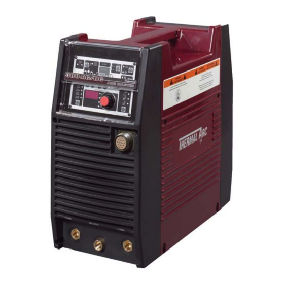
300 AC/DC ® ARCMASTER INVERTER ARC WELDER Art # A-07238 Service Manual Version No: AA.01 Issue Date: May 22, 2006 Manual No.: 0-4942B Operating Features: INVERTER... - Page 3 While the information contained in this Manual represents the Manufacturer's best judgement, the Manufacturer assumes no liability for its use. ArcMaster 300 AC/DC Inverter Arc Welder Service Manual Number 0-4942B for: Part Number 10-3098 Published by: Thermadyne Industries Inc.
-
Page 4: Table Of Contents
CONTENTS 1 SAFETY INSTRUCTIONS AND WARNINGS 1 Arc Welding Hazards................1–1 2 PRINCIPAL SAFETY STANDARDS . - Page 5 9 VOLTAGE REDUCTION DEVICE (VRD) 1 VRD Specification ................9–1 2 VRD Maintenance .
- Page 6 CONTENTS 3. 14 PCB17 (WK-5570) ............... . . 12–16 3.
-
Page 7: Safety Instructions And Warnings
ARCMASTER 300 AC/DC SECTION 1. SAFETY INSTRUCTIONS AND WARNINGS WARNING PROTECT YOURSELF AND OTHERS FROM POSSIBLE SERIOUS INJURY OR DEATH. KEEP CHILDREN AWAY. PACEMAKER WEARERS KEEP AWAY UNTIL CONSULTING YOUR DOCTOR. DO NOT LOSE THESE INSTRUCTIONS. READ OPERATING/INSTRUCTION MANUAL BEFORE INSTALLING, OPERATING OR SERVICING THIS EQUIPMENT. - Page 8 ARCMASTER 300 AC/DC 3. Use protective screens or barriers to protect others from flash and glare; warn others not to watch the arc. WARNING 4. Wear protective clothing made from durable, flame-resistant material (wool and leather) and foot protection. WELDING can cause fire or explosion.
- Page 9 ARCMASTER 300 AC/DC 2. If used in a closed area, vent engine exhaust outside and away from any building air intakes. WARNING WARNING FLYING SPARKS AND HOT METAL can cause injury. Chipping and grinding cause flying metal. As welds cool, they can throw off slag.
-
Page 10: Principal Safety Standards
ARCMASTER 300 AC/DC 1.02 Principal Safety Standards Safety in Welding and Cutting, ANSI Standard Z49.1, from American WARNING Welding Society, 550 N.W. LeJeune Rd., Miami, FL 33126. Safety and Health Standards, OSHA 29 CFR 1910, from Superintendent STEAM AND PRESSURIZED HOT COOLANT can burn of Documents, U.S. -
Page 11: Precautions De Securite En Soundage A L'arc
ARCMASTER 300 AC/DC 1.03 Precautions de Securite en Soudage à l’Arc MISE EN GARDE LE SOUDAGE A L’ARC EST DANGEREUX PROTEGEZ-VOUS, AINSI QUE LES AUTRES, CONTRE LES BLESSURES GRAVES POSSIBLES OU LA MORT. NE LAISSEZ PAS LES ENFANTS S’APPROCHER, NI LES PORTEURS DE STIMULATEUR CARDIAQUE (A MOINS QU’ILS N’AIENT CONSULTE UN MEDECIN). CONSERVEZ CES INSTRUCTIONS. - Page 12 ARCMASTER 300 AC/DC AVERTISSEMENT AVERTISSEMENT LES VAPEURS ET LES FUMEES SONT DANGEREUSES LE RAYONNEMENT DE L’ARC PEUT BRÛLER LES YEUX POUR LA SANTE. ET LA PEAU; LE BRUIT PEUT ENDOMMAGER L’OUIE. Le soudage dégage des vapeurs et des fumées L’arc de soudage produit une chaleur et des rayons dangereuses à...
- Page 13 ARCMASTER 300 AC/DC 7. Ne soudez des tôles galvanisées ou plaquées au plomb ou au cadmium que si les zones à souder ont été grattées à fond, que si AVERTISSEMENT l’espace est bien ventilé; si nécessaire portez un respirateur à ad- duction d’air.
-
Page 14: Principales Normes De Securite
ARCMASTER 300 AC/DC Les accumulateurs contiennent de l’électrolyte acide et 1. Utilisez l’équipement à l’extérieur dans des aires ouvertes et bien ventilées. dégagent des vapeurs explosives. 2. Si vous utilisez ces équipements dans un endroit confiné, les 1. Portez toujours un écran facial en travaillant sur un accumu-lateur. -
Page 15: Declaration Of Conformity
ARCMASTER 300 AC/DC 1.06 Declaration Of Conformity Manufacturer: Thermadyne Corporation Address: 82 Benning Street West Lebanon, New Hampshire 03784 The equipment described in this manual conforms to all applicable aspects and regulations of the ‘Low Voltage Directive’ (European Council Directive 73/23/EEC as amended by Council Directive 93/68/EEC) and to the National legislation for the enforcement of this Directive. -
Page 16: Introduction
Electronic copies of this manual can also be down- loaded at no charge in Acrobat PDF format by going to the Thermal Arc web site listed below and clicking on the Literature Library link: http://www.thermalarc.com 2 – 1... -
Page 17: Symbol Chart
300ACDC INTRODUCTION Symbol Chart Note that only some of these symbols will appear on your model. STICK Amperage (Shielded Metal Arc SMAW) Pulse Current Function Voltage Spot Time (GTAW) Hertz (frequency) Remote Control Seconds (Panel/Remote) Remote Function Percent Arc Control (SMAW) DC (Direct Current) Gas Post-Flow AC (Alternating Current) -
Page 18: Description
300ACDC INTRODUCTION Description The Thermal Arc Model 300ACDC is a self contained single/three -phase AC/DC arc welding power source with Constant Current (CC) output characteristics. This unit is equipped with a Digital Volt/Amperage Meter, gas control valve, built in Sloper and Pulser, lift arc starter, and high-frequency arc starter for use with Gas Tungsten Arc Welding (GTAW), Gas Tungsten Arc Welding-Pulsed (GTAW-P) Gas Tungsten Arc Weld- ing-Sloped (GTAW-S), and Shielded Metal Arc Welding (SMAW) processes. -
Page 19: Transporting Methods
300ACDC INTRODUCTION Transporting Methods These units are equipped with a handle for carrying purposes. WARNING ELECTRIC SHOCK can kill. DO NOT TOUCH live electrical parts. Disconnect input power conductors from de- energized supply line before moving the welding power source. -
Page 20: Installation
Do not connect the ground (GREEN/YELLOW) conductor to an input line terminal. WARNING Thermal Arc advises that this equipment be electri- cally connected by a qualified electrician. 3 – 1... -
Page 21: Input Power
The ARC MASTER 300ACDC is designed for use with a generator as an input power source. Con- tact an accredited Thermal Arc service agent for Figure 3-1: Electrical Input Connections the proper sizing and set-up recommendations of a generator power source system. -
Page 22: High Frequency Introduction
300ACDC INSTALLATION High Frequency Introduc- 3. Radiation from Welding Leads: Radiated interference from welding leads, although pro- tion nounced in the vicinity of the leads, diminishes rapidly with distance. Keeping leads as short The importance of correct installation of high fre- as possible will minimize this type of interfer- quency welding equipment cannot be over-empha- ence. -
Page 23: Specifications
300ACDC INSTALLATION Specifications Thermal Arc continuously strives to produce the best product possible and therefore reserves the right to change, improve or revise the specifica- Parameter 300ACDC tions or design of this or any product without prior Rated Output notice. Such updates or changes do not entitle the... -
Page 24: Operator Controls
OPERATOR CONTROLS ARC MASTER 300ACDC Controls OPERATOR CONTROLS 1. Control Knob: This control sets the selected weld parameter, rotating it clockwise increases the parameter that is indicated on the digital meter. Pushing the knob inward displays the actual welding voltage. 2. -
Page 25: Weld Process Selection For Arc Master 300Acdc
300ACDC OPERATOR CONTROLS Weld Process selection for 3. Positive Terminal: Welding current flows from the Power Source via heavy duty Dinse type ARC MASTER 300ACDC terminal (50 mm). It is essential, however, that the male plug is inserted and turned securely to achieve a sound electrical connec- Weld Mode tion. -
Page 26: Weld Parameter Descriptions For Arc Master 300Acdc
300ACDC OPERATOR CONTROLS Weld Parameter Descriptions for ARC MASTER 300ACDC Figure 4-3: ARC MASTER 300ACDC Front Panel with Parameter Description Parameter Description This parameter operates in TIG modes only and is used to provide gas to the weld zone prior to striking the arc, once the torch trigger switch has been pressed. - Page 27 300ACDC OPERATOR CONTROLS Parameter Description This parameter is used for aluminium AC TIG mode and is used to set the penetration to cleaning action ratio for the AC weld current. Generally WAVE BALANCE is set to 50% for AC STICK welding.
-
Page 28: Weld Parameters For Arc Master 300Acdc
300ACDC OPERATOR CONTROLS Weld Parameters for ARC MASTER 300ACDC Weld Mode Parameter Weld Parameter Factory Setting Incremental Unit STICK HF TIG LIFT TIG Range PRE-FLOW 0.0 to 1.0 sec 0 sec 0.1 sec HOT START 0 to 70A INITIAL CUR. 5 to 300A UP SLOPE 0 to 15 sec... -
Page 29: Power Source Features
300ACDC OPERATOR CONTROLS Power Source Features Feature Description Feature Description An error code is displayed on the Self Almost all welding parameters are New Digital Diagnosis Digital Meter when a problem adjustable. Control Using Error occurs with Primary supply volt- ... -
Page 30: Set-Up For Smaw (Stick) And Gtaw (Tig)
SET-UP FOR SMAW (STICK) AND GTAW (TIG) Conventional operating procedures apply when SET-UP FOR SMAW (STICK) AND GTAW (TIG) using the Welding Power Source, i.e. connect work lead directly to work piece and electrode lead is used to hold electrode. Wide safety margins pro- vided by the coil design ensure that the Welding Power Source will withstand short-term overload without adverse effects. - Page 31 300ACDC SET-UP FOR SMAW (STICK) AND GTAW (TIG) PAGE LEFT INTENTIONALLY BLANK 5 – 2...
-
Page 32: Sequence Of Operation
SEQUENCE OF OPERATION 8. Scroll Buttons: SEQUENCE OF OPERATION NOTE used to select the parameters to be set. The Scroll Buttons are used to select the parameters to LED's show which function is being adjusted be set. The LED's show which function is being on the Sequence Graph. -
Page 33: Slope Mode Sequence
300ACDC SEQUENCE OF OPERATION Slope Mode with repeat Set UP SLOPE time. Set (WELD) PEAK CUR current. sequence Set BASE current. Set DOWN SLOPE time. The repeat function is operated during the down slope cycle of the Slope Sequence and is active ... -
Page 34: Routine Maintenance
ROUTINE MAINTENANCE ROUTINE MAINTENANCE The only routine maintenance required for the power supply is a thorough cleaning and inspec- tion, with the frequency depending on the usage and the operating environment. WARNING Disconnect primary power at the source before opening the enclosure. Wait at least two minutes before opening the enclosure to allow the primary capacitors to discharge. - Page 35 300ACDC ROUTINE MAINTENANCE PAGE LEFT INTENTIONALLY BLANK 7 – 2...
-
Page 36: Basic Troubleshooting
WARNING There are extremely dangerous voltages and power levels present inside this product. Do not attempt to open or repair unless you are an Accredited Thermal Arc Service Agent and you have had training in power measurements and troubleshooting techniques. - Page 37 300ACDC BASIC TROUBLESHOOTING Description Possible Cause Remedy 9. Poor weld finish. Inadequate shielding gas. Increase gas flow or check gas line for gas flow problems. 10.Arc flutters during TIG welding. A. Tungsten electrode is too large A. Select the right size electrode. Refer for the welding current.
-
Page 38: Stick Welding Problems
300ACDC BASIC TROUBLESHOOTING Stick Welding Problems Description Possible Cause Remedy 1. Gas pockets or voids in weld A. Electrodes are damp. A. Dry electrodes before use. metal (Porosity). B. Welding current is too high. B. Reduce welding current. C. Surface impurities such as oil, C. - Page 39 300ACDC BASIC TROUBLESHOOTING Description Possible Cause Remedy 5. Non-metallic particles are trapped A. Non-metallic particles may be A. If bad undercut is present, clean in the weld metal (slag inclusion). trapped in undercut from previous slag out and cover with a run from a run.
-
Page 40: Power Source Problems
B. The Welding Power Source switch B. Switch ON the Welding Power is switched OFF. Source. C. Loose connections internally. C. Have an Accredited Thermal Arc Service Agent repair the connection. 2. Maximum output welding current Defective control circuit. Have an Accredited Thermal Arc can not be achieved with nominal Service Agent repair the connection. - Page 41 300ACDC BASIC TROUBLESHOOTING PAGE LEFT INTENTIONALLY BLANK 8 – 6...
-
Page 42: Voltage Reduction Device (Vrd)
In addition to the above tests and specifically in relation to the VRD fitted to this machine, the fol- lowing periodic tests should also be conducted by an accredited Thermal Arc service agent. Description IEC 60974-1 Requirements VRD Open Less than 20V;... -
Page 43: Switching Vrd On/Off
300ACDC VOLTAGE REDUCTION DEVICE (VRD) Switching VRD On/Off C) Access the VRD control by gently prying back the front panel controls to reveal the VRD on/ off potentiometer (see Figure 9-3). Switch the machine Off. A) Remove the clear plastic cover from the control CAUTION panel (see Figure 9-1). -
Page 44: Power Source Error Code
E01 resets when TH1 B. Fan ceases to operate. B. Have an Accredited about 1 second. decreases to 70°C for about Thermal Arc Service 30 seconds. Agent investigate. C. Air flow is restricted by C. Unblock vents then let vents being blocked. - Page 45 E99 error. B. Mains supply (input) B. Have an Accredited power from the primary voltage has been turned Thermal Arc Service capacitors. off. Agent or a qualified electrician check the Mains voltage and fuses.
-
Page 46: Advanced Troubleshooting
Service Manual, the subas- sembly should be replaced with a new one. The faulty subassembly should then be returned to Thermal Arc through established procedures. Figure 11-1: Switch OFF WARNING CAUTION... - Page 47 300ACDC ADVANCED TROUBLESHOOTING 2) Remove all screws and nuts on the Side Panel. 4) Pull the front panel slightly forward and pull the rear panel slightly backward. The interlocking hooks of the side case covers can now be dis- engaged from the front and rear panels. Figure 11-2: Remove screws 3) Loosen the screws on the front panel and the rear panel by turning them approximately two...
-
Page 48: Verification And Remedy To The Indicated Error Codes
300ACDC ADVANCED TROUBLESHOOTING 2.1 E01 "Over-Temperature at 6) Remove protection cover sheet by removing the plastic tabs. the primary side" Cause Occurs when an over-temperature condition of the primary IGBT is detected. Verification/Remedy a) Unit may be in thermal shutdown mode. ... -
Page 49: E02 "Over-Temperature At The Secondary Side
300ACDC ADVANCED TROUBLESHOOTING 2.2 E02 "Over-Temperature at 2.3 E03 "Transformer Over-Cur- the secondary side" rent Failure" Cause Cause Occurs when an over-temperature condition of the Occurs when excessive current is detected flow- secondary IGBT and diode are detected. ing into the primary side of the main transformer. Verification/Remedy Verification/Remedy a) Unit may be in thermal shutdown mode. -
Page 50: 2.4 E04 "Torch Cable Failure
300ACDC ADVANCED TROUBLESHOOTING 2.4 E04 "Torch Cable Failure" 2.6 E12 "Main Supply Under Volt- age" Cause Cause The combined length of the torch cable and the work cable is too long. Main supply voltage occurs at about 150V or less. Verification/Remedy Verification/Remedy a) Verify the rated duty cycles of the torch/work... -
Page 51: E82 "Rated Voltage Selection Circuit Abnormality
300ACDC ADVANCED TROUBLESHOOTING 2.8 E82 "Rated Voltage Selection c) Verify PCB4 (WK-4819) and replace it if neces- sary. Circuit abnormality" Check whether there are any abnormalities on the appearance of PCB4. Cause Replace PCB4. Refer to section 12.3.4. Rated voltage selection circuit inside the Welding Power Source is not functioning properly. -
Page 52: 2.11 E94 "Thermistor Malfunction
300ACDC ADVANCED TROUBLESHOOTING Verification and Remedy to 2.11 E94 "Thermistor malfunction" Failures without Indication Cause Codes Thermistors for detecting temperature of internal components have malfunctioned. Refer to Note on Section 11.02. Verification/Remedy 3.1 "Cooling Fan (FAN1) Failure" a) Confirm a secure connection of the harness (Fan is not rotating.) wired between CN8-9 on PCB6 (WK-5549) and Thermistors (TH1, TH2). -
Page 53: Gas Valve Failure" (No Gas Flow Through Unit)
300ACDC ADVANCED TROUBLESHOOTING 3.2 "Gas Valve Failure" (No Gas 3.3 "No Weld Output" flow through unit) When in High Frequency TIG (HF TIG) mode, if the High Frequency is not generated (present), refer to Cause "High Frequency Output Failure". Refer to section 11.3.5. -
Page 54: Operating Panel Failure" (Led's Do Not Light Properly Or Welding Setting Cannot Be Establish.)
300ACDC ADVANCED TROUBLESHOOTING c) Verify the no-load voltage (OCV). Contact the manufacturer if you find any bro- (Applies to STICK, High Frequency TIG (HF ken connectors or a damaged wiring har- TIG) mode.) nesses. Refer to the section "Verification of No-load b) Verify the connection between PCB5 voltage (OCV)"... -
Page 55: Fault Isolation Tests
300ACDC ADVANCED TROUBLESHOOTING Fault Isolation Tests b) Verify the connection between High Frequency (HF UNIT1) and the current limiting resistor (R2). 4.1 Preparation Verify the connection between HF UNIT1 and The following initial conditions must be met the current limiting resistor (R2), confirm that prior to starting any of the procedures in this the quick-disconnect terminals are inserted section. -
Page 56: Verification Of The Power Input Circuitry
300ACDC ADVANCED TROUBLESHOOTING Verification of the Power 3) Verify input voltage after the input switch (S1) using an AC voltmeter. (The capability of the Input Circuitry voltmeter should be more than 600VAC.) • Using an AC voltmeter, measure between CAUTION the points U2 and V2 on the input switch, S1. -
Page 57: Verification Of The Power Supply Voltage
300ACDC ADVANCED TROUBLESHOOTING 6) Verify bus voltage (the voltage of the electro- 2) On the PCB3 (WK-5548) and PCB6 (WK- lytic capacitor after rectification) using a DC 5549), measure the voltages according to the voltmeter. The capability of the DVM following table. -
Page 58: Verification Of The Cooling Fan, Fan1, Drive Circuitry
300ACDC ADVANCED TROUBLESHOOTING 3) If any of these voltages are not present or 2) Using the measurement taken above, follow are below a 10% tolerance, replace the the chart below for possible failure modes. PCB3 (WK-5548). Refer to section 12.3.3. Voltage FAN1 measurement. -
Page 59: Verification Of The Gas Valve, Sol1, Drive Circuitry
300ACDC ADVANCED TROUBLESHOOTING 5.4 Verification of the Gas Valve, 5.5 Verification of the primary SOL1, Drive Circuitry Diode (D1) CAUTION CAUTION Before performing any portion of the procedure Before performing any portion of the procedure below, make certain the unit is placed in the initial below, make certain the unit is placed in the initial set up condition as described in section 11.4.1 set up condition as described in section 11.4.1... -
Page 60: Verification Of The Secondary Diode (D2-D7)
300ACDC ADVANCED TROUBLESHOOTING 5.6 Verification of the secondary 1) Check whether there are any abnormalities on the appearance of PCB8-PCB11. Diode (D2-D7) 2) Verify the characteristic of the primary IGBT CAUTION (Q1-Q24), using a diode tester. Before performing any portion of the procedure 3) Refer below Table 11-7 and Figure 11-16 for below, make certain the unit is placed in the initial the checkpoints on PCB8-PCB11. -
Page 61: Verification Of The Secondary Igbt (Q25-Q26)
300ACDC ADVANCED TROUBLESHOOTING 5.8 Verification of the secondary 5.9 Verification of No-load Volt- IGBT (Q25-Q26) age (OCV) CAUTION CAUTION Before performing any portion of the procedure Before performing any portion of the procedure below, make certain the unit is placed in the initial below, make certain the unit is placed in the initial set up condition as described in section 11.4.1. - Page 62 300ACDC ADVANCED TROUBLESHOOTING b. Verify the no-load voltage (OCV) in High Fre- quency TIG mode. WARNING This welding mode produces high frequency and high voltage. Extra care shall be taken to prevent electric shock. 1) When in HF TIG mode, the unit will gener- ate high voltage.
-
Page 63: Maintenance
MAINTENANCE Maintenance List MAINTENANCE DWG No. Parts name Reference page Part No. 12- 7 W7001313 PCB2 Print Circuit Board (WK-5597) 12- 9 W7001314 PCB3 Print Circuit Board (WK-5548) PCB4 Print Circuit Board (WK-4819) 12- 10 10-6635 12- 11 W7001417 PCB5 Print Circuit Board (WK-5551) 12- 9 W7001423... - Page 64 300ACDC MAINTENANCE DWG No. Parts name Reference page Part No. Print Circuit Board (WK-5493) PCB1 12- 6 W7001312 Print Circuit Board (WK-5549) PCB6 12- 11 W7001738 Print Circuit Board PCB8 (Q1-Q6) 12- 12 W7001318 (WK-5479) (Primary IGBT) Print Circuit Board PCB9 (Q7-Q12) 12- 12 W7001318...
- Page 65 300ACDC MAINTENANCE DWG No. Parts name Reference page Part No. CON1 Remote Socket 12- 28 W7001666 Primary Diode 12- 30 10-6769 Secondary Diode 12- 30 10-6629 Secondary Diode 12- 30 10-6629 Secondary Diode 12- 30 10-6629 Secondary Diode 12- 30 10-6629 Secondary Diode 12- 30...
- Page 66 300ACDC MAINTENANCE DWG No. Parts name Reference page Part No. Coupling Coil 12- 22 W7001382 Current Trans 12- 32 W7001304 Current Trans 12- 32 FAN1 Cooling Fan 12- 24 W7001307 FCH1 Reactor 12- 22 W7001681 HCT1 Hall Current Sensor 12- 29 10-5003 Ring Core 12- 33...
-
Page 67: Service Tools
300ACDC MAINTENANCE Service Tools 2.1 Tools and parts The tools and parts to be used for maintenance are shown by icons. Long Nose Philips Head Silicon Spanner C-Ring Pliers Snap Band Pliers Screwdriver Compound 2.2 Notes of disassembly and assembly NOTE When removing the locking type connectors and board supporters, disengage the locking mechanism first and then disconnect them. -
Page 68: Replacement Procedure
300ACDC MAINTENANCE Replacement Procedure 3.1 PCB1 (WK-5493) 1) Remove the Side Panel. [Reference page : 11-1] 2) Remove the PCB2 (WK-5597). [Reference page : 12-7] 3) Remove the diode (D1). [Reference page : 12-30] 4) Remove the current trans (CT2/CT3). [Reference page : 12-33] 5) Remove the gas tube. -
Page 69: Pcb2 (Wk-5597)
300ACDC MAINTENANCE 8) Remove the 18 screws and remove the PCB1 (WK-5493). 3.2 PCB2 (WK-5597) 1) Remove the Side Panel. [Reference page : 11-1] 2) Remove the screw and then disconnect the four ground terminals. Disconnect the 19 connectors. CN17 CN22 CN21... -
Page 70: Pcb3 (Wk-5548), Pcb7 (Wk-5550)
300ACDC MAINTENANCE 4) Remove the six screws, three terminals and three connectors from the PCB2 (WK-5597). 5) Remove the two PCB supporters and then the PCB2 (WK-5597) and insulation sheet. 3.3 PCB3 (WK-5548), PCB7 (WK-5550) 1) Remove the Side Panel. [Reference page : 11-1] 2) Remove the PCB4 (WK-4819). - Page 71 300ACDC MAINTENANCE 6) Remove the screw and then the four ground terminals. Remove the four screws and then remove the PCB3 and PCB7 unit. Disconnect the three connectors from the PCB7 (WK-5550). CN14 CN15 CN13 7) Disconnect the one connector and remove the two screws, and then remove the PCB7 (WK-5550) from the PCB3 (WK-5548).
-
Page 72: Pcb4 (Wk-4819)
300ACDC MAINTENANCE 3.4 PCB4 (WK-4819) 1) Remove the Side Panel. [Reference page : 11-1] 2) Disconnect the two connectors. Remove the two screws and three connectors and remove the PCB4 (WK-4819). 3.5 PCB5 (WK-5551) 1) Remove the Side Panel. [Reference page : 11-1] 2) Remove the PCB6 (WK-5549). -
Page 73: Pcb6 (Wk-5549)
300ACDC MAINTENANCE 3.6 PCB6 (WK-5549) 1) Remove the Side Panel. [Reference page :11-1] 2) Disconnect the six connectors. CN21 CN17 CN20 3) Remove the three screws and five connectors. Remove the PCB6 (WK-5549). CN27 CN18 CN32 CN30 CN31 3.7 PCB8, PCB9 (WK-5479) and Q1-Q12 “Primary IGBT” 1) Remove the Side Panel. -
Page 74: 3.8 Pcb10, Pcb11 (Wk-5479) And Q13-Q24 "Primary Igbt
300ACDC MAINTENANCE 3.8 PCB10, PCB11 (WK-5479) and Q13-Q24 “Primary IGBT” 1) Remove the Side Panel. [Reference page : 11-1] 2) Remove the eight screws and four device clips. Remove the four connectors and six screws. Remove the PCB10 (WK-5479) and PCB11 (WK-5479). ... -
Page 75: Pcb13 (Wk-5528)
300ACDC MAINTENANCE 3.10 PCB13 (WK-5528) 1) Remove the Side Panel. [Reference page : 11-1] 2) Remove the operation cover. 3) Remove the jog dial cap. Holding the jog dial down, loosen the screw and remove the jog dial. 4) Disconnect the one connector from the PCB12 (WK-5527). Remove the nut, washer and terminal. -
Page 76: Pcb14 (Wk-5594) (T1-T2 "Main Trans Former")
300ACDC MAINTENANCE 5) Remove the one connector and two screws. Remove the PCB13 (WK-5528). 3.11 PCB14 (WK-5594) (T1-T2 “Main Trans former”) 1) Remove the Side Panel. [Reference page : 11-1] 2) Remove the coupling coil (CC1). [Reference page : 12-23] 3) Remove the PCB16 (WK-5569). -
Page 77: Pcb15 (Wk-5606)
300ACDC MAINTENANCE 8) Remove the four screws from the PCB1 (WK-5477). Remove the seven terminals. The cables is drawn out. 9) Remove the four screws and two terminals from the bottom. Remove the two screws from the rear side and pull out the PCB14 (WK-5594). Remove the four screws and then remove the bus bar. 3.12 PCB15 (WK-5606) ... -
Page 78: Pcb16 (Wk-5569)
300ACDC MAINTENANCE 3.13 PCB16 (WK-5569) 1) Remove the Side Panel. [Reference page : 11-1] 2) Remove the gas tube and two terminals. Remove the six connectors, two screws and two terminals. 3) Remove the four screws and then the PCB16 (WK-5569). 3.14 PCB17 (WK-5570) ... -
Page 79: Pcb20 (Wk-5499)
300ACDC MAINTENANCE 4) Remove the three print circuit board supporters from the PCB17 (WK-5570). 3.15 PCB20 (WK-5499) 1) Remove the Side Panel. [Reference page : 11-1] 2) Remove the gas tube from the front side. 3) Disconnect the two connectors. Remove the three print circuit board supporters and then remove the PCB20 (WK-5499). -
Page 80: Pcb21 (Wk-4917)
300ACDC MAINTENANCE 3.16 PCB21 (WK-4917) 1) Remove the Side Panel. [Reference page : 11-1] 2) Remove the six screws from the switch (S1) and remove the six terminals. 3) Remove the four screws and then open the rear plate. 4) Disconnect the one connector. -
Page 81: Pcb22 (Wk-5022)
300ACDC MAINTENANCE 5) Remove the three screws and the bus bar from the PCB21 (WK-4917). 3.17 PCB22 (WK-5022) 1) Remove the Side Panel. [Reference page : 11-1] 2) Disconnect one connector. Remove four screws and one terminal. Remove the PCB19 (WK-5022). 3) Remove three board supports. -
Page 82: Current Limiting Resistor (R6)
300ACDC MAINTENANCE 3.18 Current Limiting Resistor (R6) 1) Remove the Side Panel. [Reference page : 11-1] 2) Remove the high freguency unit (HF.UNIT1). [Reference page : 12-28] 3) Remove the screws and then remove the current limiting resistor (R6). 3.19 Discharge Resistor (R3) ... -
Page 83: Resistor (R7, R8)
300ACDC MAINTENANCE 3.20 Resistor (R7, R8) 1) Remove the Side Panel. [Referance page : 11-1] 2) Remove four screws and three terminals. 3) Cut off one snap band and disconnect one connector. Remove the one screw. 4) Remove two screws and remove the PCB22 unit. 12 –... - Page 84 300ACDC MAINTENANCE 5) Remove four screws and open the rear panel. 6) Remove four screws and six terminals. Remove the resistors (R7 and R8). 12 – 22...
-
Page 85: Coupling Coil (Cc1)
300ACDC MAINTENANCE 3.21 Coupling Coil (CC1) 1) Remove the Side Panel. [Reference page : 11-1] 2) Remove the gas tube. Remove the two bolts, and one terminal. Remove the four screws and open the front cabinet. 3) Remove the two terminals. Remove one screw, four terminals, and one nut. Remove one screw and detach the coupling coil (CC1). -
Page 86: Primary Thermistor (Th1)
300ACDC MAINTENANCE 7) Remove the one screw and one terminal. Remove the four screws and inductor (FCH1). 3.23 Primary Thermistor (TH1) 1) Remove the Side Panel. [Reference page : 11-1] 2) Disconnect the one connector. Remove the one screw and then detach the primary thermistor (TH1). ... -
Page 87: Secondary Thermistor (Th2)
300ACDC MAINTENANCE 3.24 Secondary Thermistor (TH2) 1) Remove the Side Panel. [Reference page : 11-1] 2) Remove the PCB16 (WK-5569). [Reference page : 12-16] 3) Cut the three snap bands and disconnect the one connector. Remove the one screw and secondary thermister (TH2). -
Page 88: Solenoid Valve (Sol1)
300ACDC MAINTENANCE 3) Cut the one snap band and disconnect the one connector. CN11 4) Remove the two screws and detach the cooling fan (FAN1). Do not have the wrong direction of the fan when reinstalling. 3.26 Solenoid Valve (SOL1) 1) Remove the Side Panel. -
Page 89: Main On/Off Switch (S1)
300ACDC MAINTENANCE 3) Remove the C ring and detach the solenoid valve (SOL1). When reinstalling, make sure that the C ring seats in the solenoid valve groove. 3.27 Main ON/OFF Switch (S1) 1) Remove the Side Panel. [Reference page : 11-1] 2) Remove the six screws and six terminals. -
Page 90: Remote Socket (Con1)
300ACDC MAINTENANCE 3.28 Remote Socket (CON1) 1) Remove the Side Panel. [Reference page : 11-1] 2) Remove the reactor (L105). [Reference page : 12-36] 3) Disconnect the three connectors. Remove the one screw and four ground terminals. CN13 CN15 CN14 4) Remove the two screws and disconnect the remote socket (CON1). -
Page 91: Hall Current Sensor (Hct1)
300ACDC MAINTENANCE 3) Remove the two screws and detach the high freguency unit (HF. UNIT1). 3.30 Hall Current Sensor (HCT1) 1) Remove the Side Panel. [Reference page : 11-1] 2) Remove the PCB16 (WK-5569). [Reference page : 12-16] 3) Remove the PCB20 (WK-5499). [Reference page : 12-17] 4) Remove the PCB17 (WK-5570). -
Page 92: Primary Diode (D1)
300ACDC MAINTENANCE 7) Remove the connector, three screws and one terminal. Remove the bus bar. Remove the hall current sensor (HCT1). 3.31 Primary Diode (D1) 1) Remove the Side Panel. [Reference page : 11-1] 2) Remove the PCB3 (WK-5548). [Reference page : 12-8] 3) Remove four screws and three terminals. -
Page 93: Secondary Diode (D2-D7)
300ACDC MAINTENANCE 5) Remove two screws and remove the PCB22 unit. 6) Remove the six screws and 14 terminals. Remove the two screws and then detach the primary diode (D1). Before installing a new diode, apply a uniform coat of silicone compound (Shinetsu Silicone G-747 or equivalent) on the base. -
Page 94: 3.33 Secondary Igbt (Q25-Q26) And Pcb18-Pcb19
300ACDC MAINTENANCE 5) Remove the 12 screws and then detach the secondary diodes (D2, D3, D4, D5, D6, D7). Do not have the wrong direction of the diodes when reinstalling. Before installing a new diodes, apply a uniform coat of silicone compound (Shinetsu Silicone G-747 or equivalent) on the base. -
Page 95: Current Trans (Ct2, Ct3)
300ACDC MAINTENANCE 3.34 Current Trans (CT2, CT3) 1) Remove the Side Panel. [Reference page : 11-1] 2) Remove four screws and three terminals. 3) Cut off one snap band and disconnect one connector. Remove the one screw. 4) Remove two screws and remove the PCB22 unit. 12 –... -
Page 96: Ring Core (L1)
300ACDC MAINTENANCE 5) Remove the gas tube and two terminals. Remove the four screws and open the rear cabinet. 6) Cut the three snap bands and remove the connector from the PCB3 (WK-5548). Remove two screws and three terminals from the PCB1 (WK-5493). Cut two snap bands and remove the current trans (CT2, CT3). - Page 97 300ACDC MAINTENANCE 3) Cut off one snap band and disconnect one connector. Remove the one screw. 4) Remove two screws and remove the PCB22 unit. 5) Remove the gas tube and two terminals. Remove the four screws and open the rear cabinet. 12 –...
-
Page 98: Ring Core (L105)
300ACDC MAINTENANCE 6) Remove the two screws and three terminals. Cut the snap band and remove the ring core (L1). 3.36 Ring Core (L105) 1) Remove the Side Panel. [Reference page : 11-1] 2) Remove the operation cover. 3) Remove the four screws. Pull out the operation panel and bring it down. 12 –... -
Page 99: Reactor (L101)
300ACDC MAINTENANCE 4) Remove the ring core (L105). 3.37 Reactor (L101) 1) Remove the Side Panel. [Reference page: 11-1] 2) Remove four screws and remove the three ground cables. 3) Disconnect the connector CN1 on the PCB22. Remove the screw.. 12 –... -
Page 100: Reactor (L102)
300ACDC MAINTENANCE 4) Remove the PCB22 unit. 5) Cut the snap band. Remove the reactor (L101) from the Input cable. 3.38 Reactor (L102) 1) Remove the Side Panel. [Reference page: 11-1] 2) Remove four screws and three terminals. 12 – 38... - Page 101 300ACDC MAINTENANCE 3) Cut off one snap band and disconnect one connector. Remove the one screw. 4) Remove two screws and remove the PCB22 unit. 5) Remove six screws, nine terminals and remove the reactor (L102). 12 – 39...
-
Page 102: Reactor (L103)
300ACDC MAINTENANCE 3.39 Reactor (L103) 1) Remove the Side Panel. [Reference page: 11-1] 2) Remove one screw and two terminals. 3) Remove four screws and open the rear panel. Remove one nut, one washer and one terminal. 4) Cut off one snap band. Remove the reactor (L103). 12 –... -
Page 103: Appendix 1 Parts List
APPENDIX 1 PARTS LIST Equipment Identification How To Use This Parts List All identification numbers as described in the The Parts List is a combination of an illustra- Introduction chapter must be furnished when tion and a corresponding list of parts which ordering parts or making inquiries. - Page 104 300ACDC PARTS LIST DWG No. Part No. Description Additional Information QTY. PCB13 W7001320 PCB, gen 3.1, IPS WK-5528 U01 ENCODER PCB PCB14 W7001435 PCB, gen 3.1, IPS WK-5594 01 TRANS PCB PCB15 W7001321 PCB, gen 3.1, IPS WK-5606 U01 DIODE SNUBBER PCB PCB16 W7001433 PCB, gen 3.1, IPS...
- Page 105 300ACDC PARTS LIST DWG No. Part No. Description Additional Information QTY. W7001350 Heatsink, gen 3.1, IPS E1B870100 W7001351 Spring Clip,IGBT, gen 3.1, IPS E1B850100 W7001352 Chassis, PCB1, gen 3.1, IPS J5B017500 W7001353 Chassis, gen 3.1, IPS J3C356600 10-6665 Knob, gen 3.1, IPS 2621603 10-6666 Knob Cap, gen 3.1, IPS...
- Page 106 300ACDC PARTS LIST...
- Page 107 300ACDC PARTS LIST 4 96...
-
Page 108: Appendix 2 Connection Wiring Guide
APPENDIX 2 CONNECTION WIRING GUIDE APPENDIX 2 Connection Wiring Guide Destination Destination ↔ CN33 ↔ PCB2 PCB4 PCB3 PCB6 CN20 ↔ PCB2 PCB3 PCB4 ↔ ↔ PCB2 PCB6 HCT1 ↔ ↔ PCB2 PCB6 ↔ PCB21 ↔ PCB2 PCB6 PCB16 ↔ CN17 ↔... - Page 109 THIS PAGE LEFT INTENTIONALLY BLANK...
-
Page 110: Appendix 3 Interconnect Diagram
APPENDIX 3 INTERCONNECT DIAGRAM INTERCONNECT DIAGRAM APPENDIX 3 INTERCONNECT DIAGRAM TB13 TB10 TB11 TB14 TB15 TB12 PCB8 PCB10 PCB1 K(7) Main IGBT IGBT G(6) Circuit Gate Gate L102 Board Circuit Circuit [WK-5493] R(3) Board Board [WK-5479] [WK-5479] L101 S(4) T(5) L103 1 2 3 4 5 Ground... - Page 111 300ACDC INTERCONNECT DIAGRAM PCB15 DIODE Snubber PCB17 Circuit Board IGBT Snubber [WK-5606] Circuit Board 1 2 3 PCB14 [WK-5570] +Output TRANS FCH1 Board Terminal [WK-5594] TB35 HCT1 PCB18 PCB19 TB33 IGBT Gate IGBT Gate Circuit Board Circuit Board TB21 [WK-3367] [WK-3367] TB34 1 2 3 4 5...
-
Page 112: Appendix 4 Diode Testing Basics
APPENDIX 4 DIODE TESTING BASICS DIODE TESTING BASIC APPENDIX 4 DIODE Testing Basic Testing of diode modules requires a digital Volt/ Ohmmeter that has a diode test scale. 1. Locate the diode module to be tested. 2. Remove cables from mounting studs on diodes to isolate them within the module. - Page 114 LIMITED WARRANTY AND SCHEDULE This information applies to Thermadyne products that were purchased in the United Kingdom April 2006 Thermadyne guarantees the proposed product to be free from defects in material or workmanship when operated in accordance with the written instructions as defined in the owner’s manual supplied with the machine. Thermadyne welding products are manufactured for use by commercial and industrial users and trained personnel with experience in the use and maintenance of electrical welding and cutting equipment.
-
Page 115: Global Customer Service Contact Information
GLOBAL CUSTOMER SERVICE CONTACT INFORMATION Thermadyne Asia Sdn Bhd Thermadyne USA Lot 151, Jalan Industri 3/5A 2800 Airport Road Rawang Integrated Industrial Park - Jln Batu Arang Denton, Tx 76207 USA 48000 Rawang Selangor Darul Ehsan Telephone: (940) 566-2000 West Malaysia 800-426-1888 Telephone: 603+ 6092 2988 Fax: 800-535-0557... - Page 116 World Headquarters Thermadyne Holdings Corporation Suite 300, 16052 Swingley Ridge Road St. Louis, MO 63017 Telephone: (636) 728-3000 Fascimile: (636) 728-3010 Email: sales@thermalarc.com www.thermalarc.com...
Need help?
Do you have a question about the ARCMASTER 300 AC/DC and is the answer not in the manual?
Questions and answers