Thermal Arc PowerMaster 400SP Automation Service Manual
Powermaster automation
Hide thumbs
Also See for PowerMaster 400SP Automation:
- Service manual (146 pages) ,
- Operator's manual (70 pages) ,
- Service manual (40 pages)
Table of Contents
Advertisement
Quick Links
Download this manual
See also:
Operator's Manual
Advertisement
Table of Contents
Troubleshooting

Related Manuals for Thermal Arc PowerMaster 400SP Automation


Summary of Contents for Thermal Arc PowerMaster 400SP Automation
-
Page 1: Service Manual
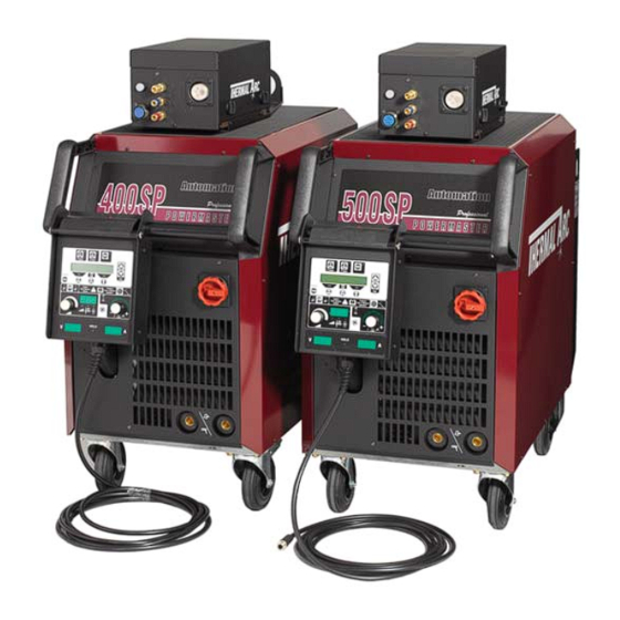
400SP POWERMASTER 500SP AUTOMATION Art # A-07790 Service Manual Revision: AB Issue Date: October 30, 2008 Manual No.: 0-4971B Operating Features:... - Page 3 While the information contained in this Manual represents the Manufacturer's best judgement, the Manufacturer assumes no liability for its use. Service Manual Number 0-4971B for: PowerMaster 500SP Automation Bw Robotic (US) W1000602 PowerMaster 400SP Automation Bw Robotic (US) W1000402 SP4000R Automation Wire Feeder (US) W3000302 Remote Operation Panel Pendant...
-
Page 4: Table Of Contents
INSTALLATION ..................3-1 3.01 Location ......................3-1 3.02 Voltage Changeover ..................3-1 3.03 Connecting 3-Phase Input Power to 400SP or 500SP ........3-2 3.04 Connecting Single-Phase Input Power to 400SP or 500SP ......3-4 3.05 Quick Start Set Up ..................3-6 3.06 Recommended Setup for MIG ................ - Page 5 TABLE OF CONTENTS SECTION 6: TABLE OF CONTENTS (continued) MANUAL GMAW WELDING ................ 6-1 6.01 Types of Weld Transfer Modes ............... 6-1 6.02 Holding and Manipulating the Torch ............... 6-2 6.03 Basics of Pulsed Arc Welding ................. 6-4 6.04 Pulsed Arc Welding Parameters ..............6-5 6.05 Smart, Pulse or TwinPulse GMAW Welding ............
- Page 6 9.01 Equipment Identification ................. 9-1 9.02 How To Use This Parts List ................9-1 9.03 PowerMaster 400SP & 500SP Robotic Exploded View Parts List (1 of 2) ..9-2 9.04 PowerMaster 400SP & 500SP Robotic Exploded View Parts List (2 of 2) ..9-4 9.05 PowerMaster 400SP Power Module ...............
-
Page 7: Safety Instructions And Warnings
POWERMASTER 400SP, 500SP AUTOMATION SECTION 1: SAFETY INSTRUCTIONS AND WARNINGS WARNING PROTECT YOURSELF AND OTHERS FROM POSSIBLE SERIOUS INJURY OR DEATH. KEEP CHILDREN AWAY. PACEMAKER WEARERS KEEP AWAY UNTIL CONSULTING YOUR DOCTOR. DO NOT LOSE THESE INSTRUCTIONS. READ OPERATING/INSTRUCTION MANUAL BEFORE INSTALLING, OPERATING OR SERVICING THIS EQUIPMENT. - Page 8 POWERMASTER 400SP, 500SP AUTOMATION Sparks and spatter fly off from the welding arc. The flying sparks and hot metal, weld spatter, hot workpiece, and hot equipment can cause fires and WARNING burns. Accidental contact of electrode or welding wire to metal objects can cause sparks, overheating, or fire.
- Page 9 POWERMASTER 400SP, 500SP AUTOMATION 1. Wear approved face shield or safety goggles. Side shields 1. Stop engine before checking or adding fuel. recommended. 2. Do not add fuel while smoking or if unit is near any sparks or 2. Wear proper body protection to protect skin.
-
Page 10: Principal Safety Standards
POWERMASTER 400SP, 500SP AUTOMATION 1. Do not remove radiator cap when engine is hot. Allow engine 1.02 Principal Safety Standards to cool. Safety in Welding and Cutting, ANSI Standard Z49.1, from 2. Wear gloves and put a rag over cap area when removing cap. -
Page 11: Symbol Chart
POWERMASTER 400SP, 500SP AUTOMATION 1.03 Symbol Chart Note that only some of these symbols will appear on your model. Wire Feed Function Single Phase Wire Feed Towards Workpiece With Three Phase Output Voltage Off. Three Phase Static Frequency Converter- Welding Gun... -
Page 12: Precautions De Securite En Soudage A L'arc
POWERMASTER 400SP, 500SP AUTOMATION 1.04 Precautions De Securite En Soudage A L’arc MISE EN GARDE LE SOUDAGE A L’ARC EST DANGEREUX PROTEGEZ-VOUS, AINSI QUE LES AUTRES, CONTRE LES BLESSURES GRAVES POSSIBLES OU LA MORT. NE LAISSEZ PAS LES ENFANTS S’APPROCHER, NI LES PORTEURS DE STIMULATEUR CARDIAQUE (A MOINS QU’ILS N’AIENT CONSULTE UN MEDECIN). - Page 13 POWERMASTER 400SP, 500SP AUTOMATION AVERTISSEMENT AVERTISSEMENT LES VAPEURS ET LES FUMEES SONT LE RAYONNEMENT DE L’ARC PEUT BRÛLER LES DANGEREUSES POUR LA SANTE. YEUX ET LA PEAU; LE BRUIT PEUT ENDOMMAGER L’OUIE. Le soudage dégage des vapeurs et des fumées dangereuses à...
- Page 14 POWERMASTER 400SP, 500SP AUTOMATION 7. Ne soudez des tôles galvanisées ou plaquées au plomb ou 1. Portez un écran facial ou des lunettes protectrices au cadmium que si les zones à souder ont été grattées à approuvées. Des écrans latéraux sont recommandés.
-
Page 15: Principales Normes De Securite
POWERMASTER 400SP, 500SP AUTOMATION 1. Portez toujours un écran facial en travaillant sur un accumu- lateur. AVERTISSEMENT 2. Arrêtez le moteur avant de connecter ou de déconnecter des câbles d’accumulateur. LE CARBURANT PEUR CAUSER UN INCENDIE OU 3. N’utilisez que des outils anti-étincelles pour travailler sur un UNE EXPLOSION. -
Page 16: Graphique De Symbole
POWERMASTER 400SP, 500SP AUTOMATION 1.07 Graphique de Symbole Seulement certains de ces symboles apparaîtront sur votre modèle. Déroulement du Fil Sous Tension Mono Phasé Alimentation du Fil Vers la Pièce de Fabrication Hors Tension Trois Phasé Hors Tension Tri-Phase Statique... -
Page 17: Introduction
Electronic copies of this manual can also be down- loaded at no charge in Acrobat PDF format by going to the Thermal Arc web site listed below and clicking on the Literature Library link: http://www.thermalarc.com October 30, 2008... -
Page 18: Machine Components
POWERMASTER 400SP, 500SP AUTOMATION 2.04 Machine Components (16) (15) (14) (13) (12) (11) Art # A-07791 (10) 1. SP4000R Wire Feeder 10. Wheeling Gear 2. MIG Torch Connection Socket 11. Remote Pendant Operating Panel 3. Handle 12. Protective Cover, Operation Panel 4. -
Page 19: Power Supply Specifications (Part 1)
POWERMASTER 400SP, 500SP AUTOMATION 2.05 Power Supply Specifications (part 1) PowerMaster Power Source Part Numbers 400SP 500SP Automation Power Supply with Integrated Torch Water Cooling System W1000402 W1000602 Summary Specifications Input Mains Voltage (50/60 Hz) V 208 230 400 460 208 230 400 460... -
Page 20: Power Supply Specifications (Part 2)
POWERMASTER 400SP, 500SP AUTOMATION 2.06 Power Supply Specifications (part 2) Electrical Specifications for SMAW / STICK with Three-Phase Input Power Welding Output 400SP 500SP Duty Cycle 100% 3 Phase Duty Cycle 60% 3 Phase Duty Cycle at Maximum Current 3 Phase 50%@380A, 35.2V 60%@480A, 39.2V... -
Page 21: Wire Feeder Specifications
POWERMASTER 400SP, 500SP AUTOMATION 2.07 Wire Feeder Specifications Wirefeeder Part Numbers SP4000W SP4000R Wirefeeder suits water cooled torch W3000102 – Wirefeeder suits Automation Power Source – W3000302 Welding Output Weldable Wire Steel & Stainless Steel Ø in .023 – .045 .023 –... - Page 22 POWERMASTER 400SP, 500SP AUTOMATION October 30, 2008...
-
Page 23: Installation
These fuses will have to be replaced before the machine can operate. Thermal Arc advises that a suitable Mains Plug and cable be fitted to this equipment by a qualified electrical trades-person. WARNING 3.01 Location... -
Page 24: Connecting 3-Phase Input Power To 400Sp Or 500Sp
POWERMASTER 400SP, 500SP AUTOMATION 3.03 Connecting 3-Phase Input Power to 400SP or 500SP WARNINGS Installation must meet all National and Local Codes - have only qualified persons make this instal- lation. Disconnect and lockout/tagout input power before connecting input conductors from unit. - Page 25 POWERMASTER 400SP, 500SP AUTOMATION WARNING Never connect the safety ground screw to one of the three line phases. This would represent a serious electrical shock hazard. The wiring to this machine should be performed by a qualified person only. A. Input Power Conductors (Customer Supplied Cord) Select size of conductors using table.
-
Page 26: Connecting Single-Phase Input Power To 400Sp Or 500Sp
POWERMASTER 400SP, 500SP AUTOMATION 3.04 Connecting Single-Phase Input Power to 400SP or 500SP WARNINGS Installation must meet all National and Local Codes - have only qualified persons make this instal- lation. Disconnect and lockout/tagout input power before connecting input conductors from unit. - Page 27 POWERMASTER 400SP, 500SP AUTOMATION WARNING Never connect the safety ground screw to one of the three line phases. This would represent a serious electrical shock hazard. The wiring to this machine should be performed by a qualified person only. A. Input Power Conductors (Customer Supplied Cord) Select size of conductors using table.
-
Page 28: Quick Start Set Up
WARNING in the front panel. 3. Locate the thumbscrew on the gun adapter Thermal Arc advises that a suitable Mains inside the unit. Loosen the thumbscrew and Plug be fitted to this equipment by a insert the gun cable end into the gun adapter qualified electrical trades-person. - Page 29 POWERMASTER 400SP, 500SP AUTOMATION B. How To Connect The Work lead E. How To Install The Wire Spool Connect the work lead to the Negative connection and Open the wire feed compartment lid on the power fasten it by turning the connector to the right. Connect supply or wirefeed case and un-screw the nut from the Work clamp to the workpiece or the welding table.
- Page 30 POWERMASTER 400SP, 500SP AUTOMATION F. Insertion Of The Wire Electrode Press the inch switch button until the wire appears approximately 3/4 inch (20 mm) out of the Screw out the contact tip in the MIG torch handset. torch neck. Open the wire feed compartment lid on the power supply or wirefeed case.
- Page 31 POWERMASTER 400SP, 500SP AUTOMATION H. How To Refill The Cooling Fluid How To Configure The Power Supply For Aluminium Welding Only use original MIG/TIG coolant for refill. It provides protection against frost down to 4°F Change the feedrolls to U groove for aluminium wire (-20°C).
-
Page 32: Pulsemaster Pma512S-3545 500 Amp Weld Gun (When Welding By Hand)
TWECO Pulsemaster MIG guns may be fitted to many different types of MIG welding Power Supplies so that your whole shop can be converted to TWECO Pulsemaster. Not only will this give greater reliability (and hence greater productivity) but it will reduce stockholding of consumable parts. See your Thermal Arc distributor for details. -
Page 33: Installing A New Wire Conduit
POWERMASTER 400SP, 500SP AUTOMATION 3.08 Installing A New Wire Conduit NOTE When the conduit is fully inserted into the 1. Be sure the MIG gun cable is arranged in a straight cable assembly and the conduit stop is line, free from twists, when installing or removing firmly against the Connector Plug, the a wire conduit. - Page 34 POWERMASTER 400SP, 500SP AUTOMATION October 30, 2008 3-12...
-
Page 35: Manual Operation
POWERMASTER 400SP, 500SP AUTOMATION SECTION 4: MANUAL OPERATION 4.01 General Safety Precautions Read and understand the safety instructions at the beginning of this manual prior to operating this machine. WARNING: Be sure to put on proper protective clothing and eye safeguards (welding coat, apron, gloves, and welding helmet, with proper lenses installed). -
Page 36: Welding Controls
POWERMASTER 400SP, 500SP AUTOMATION (46) ”Welding wire diameter” push-button For diameter selection of the wire to be welded. The push-button is also used for the “End” function, with which you can move back 4.02 Welding Controls to the previous menu level. - Page 37 POWERMASTER 400SP, 500SP AUTOMATION (55) “Primary parameter” indicator lights These lights show which primary parameter is currently displayed in the multifunction dis- play (54). Current / voltage display (56) “Primary parameter” push-button The actual welding voltage and welding current values For switching between welding current, ma- are indicated during welding.
-
Page 38: Menu Structure
POWERMASTER 400SP, 500SP AUTOMATION 4.03 Menu Structure Main Menu Level 1 “Extras” Level 2 Remark Gas pre-flow 0 – 10 sec.; not in SMAW/STICK electrode process Start current 20 % – 200 % of the welding current Start current time 0 –... -
Page 39: Main Menu
POWERMASTER 400SP, 500SP AUTOMATION Level 1 Main Menu “Extras” Level 2 Enter menu item by pressing both keys (51) at the same time Gas pre - flow 1 Machine data Operating system Master Start current Operating system Process Change between... - Page 40 POWERMASTER 400SP, 500SP AUTOMATION 1. Save/Programming jobs: a. Determine the optimal welding values. b. Press the “TT Save” button (45) (Save LED flashes). A. Secondary Parameters (Menu Main Level) c. Select the target job number with the push- buttons (44) (-) and (48) (+) or with the smart torch rocker, and confirm with the “TT Enter”...
- Page 41 POWERMASTER 400SP, 500SP AUTOMATION c. Hold the “TT Enter” push-button (47) pressed for two seconds (the decimal point between the job set and the job number lights up). d. The cursor is moved with the 5. Re-saving/Re-programming jobs: push-buttons (51). At the end of the line, the a.
-
Page 42: Special Functions
POWERMASTER 400SP, 500SP AUTOMATION D. Code lock function The lock function in menu Extras is secured with a code lock. A three-digit code must be entered before the lock function can be changed. Only after the 4.04 Special functions correct code is entered, the lock function can be altered. -
Page 43: Smart Gmaw, Pulse Gmaw & Twinpulse Programs
POWERMASTER 400SP, 500SP AUTOMATION 4.05 Smart GMAW, Pulse GMAW & TwinPulse Programs Material Shield Wire Program Smart GMAW Pulse GMAW TwinPulse size Number Current Range Current Range Current Range Type Name Ar / CO2 / O2 / He max min... -
Page 44: Welding Setting Selection Guide
POWERMASTER 400SP, 500SP AUTOMATION 4.06 Welding Setting Selection Guide Base Material Thickness Guide Wire Gas Combinations 320SP 400SP 500SP Decimal Fraction Gauge Decimal Synergic Synergic Synergic Pulse Pulse Pulse Material Shield Steel Smart Smart Smart &Twin &Twin &Twin Thickness Thickness... - Page 45 POWERMASTER 400SP, 500SP AUTOMATION Three Steps To GMAW (MIG) Welding 1.Set Variables A) Select Process : MANUAL GMAW SMART GMAW PULSE GMAW TWIN PULSE B) Select Wire Type C) Select Wire Size D) Select Shielding Gas 2.Set Function E) Set Trigger to 2T or 4T.
- Page 46 POWERMASTER 400SP, 500SP AUTOMATION October 30, 2008 4-12...
-
Page 47: Robotic Operation
ROBOTIC OPERATION 5.01 Robot Interface INT06 The Robot interface INT06 is for connection between the PowerMaster 400SP/500SP Automation power sources and the robot control. There are different analog and digital in-outputs available to allow an individual adaptation between welding power source and robot control. -
Page 48: Analog Inputs
POWERMASTER 400SP, 500SP AUTOMATION 5.03 Analog Inputs The eight analog inputs are designed for a voltage of 0 to +10V DC. Programming the analog inputs (assign- ment to welding parameters) is made with a PC with CAN interface (see PC Program Robot Tool) or directly at the power source over the front panel (menu Extras, Robot Interface). -
Page 49: Robot Interface Schematic
POWERMASTER 400SP, 500SP AUTOMATION 5.04 Robot Interface Schematic GND 24VDC digital Art # A-07832 Power Source + 24VDC digital X3/9 Program or job setting bit 2 X4/9 X14/1 X1/1 X3/10 Program or job setting bit 2 X4/10 X14/2 X1/2 X3/11... - Page 50 POWERMASTER 400SP, 500SP AUTOMATION LEDs on Robot Interface INT06 PC Board Designation State Meaning 1 (red) malfunction lit weak Microcontroller not programmed blinking supply voltage not ok INT06 ok 2 (green) supply voltage internal supply voltage +5V DC is ok...
-
Page 51: Robot Interface Int06 Pc Board Schematic
POWERMASTER 400SP, 500SP AUTOMATION 5.05 Robot Interface INT06 PC Board Schematic LED3 LED16 LED17 LED18 LED2 LED4 LED1 LED15 LED5 650.5282.x INT06 RP367/1 D00.0110.0-00 Art # A-07940 Connector Description CAN connector Internal programming connector Flat ribbon connector to 42 pin Harting socket (digital and analog inputs) -
Page 52: 42-Pin Harting Socket
POWERMASTER 400SP, 500SP AUTOMATION 5.06 42-Pin Harting Socket Art # A-07827 October 30, 2008... - Page 53 POWERMASTER 400SP, 500SP AUTOMATION Harting Socket Pin Descriptions October 30, 2008...
- Page 54 POWERMASTER 400SP, 500SP AUTOMATION Harting Socket Pin Descriptions (Con't) October 30, 2008...
- Page 55 POWERMASTER 400SP, 500SP AUTOMATION Other Analog Parameters Designation Description Signal Function pre gas time Control voltage 0-10V for the pre gas time. 0 sec. 10V DC 10 sec. gas post time Control voltage 0-10V for the gas post time. 10V DC 300% twinpulse current change Control voltage 0-10V for the twinpulse current change.
-
Page 56: Configuration At Front Panel Menu
POWERMASTER 400SP, 500SP AUTOMATION 5.07 Configuration at Front Panel Menu The INT06 can also be programmed at the front panel in menu "Extras, Robot Interface". The eight analog inputs can be enabled or disabled. So it is not necessary to open the machine and set the DIP switches. If there are not enough digital outputs available at the robot control to select a welding program, it is possible to select three different pre-defined welding programs with only two digital outputs. -
Page 57: Robot Tool Software Installation
POWERMASTER 400SP, 500SP AUTOMATION 5.08 Robot Tool Software Installation 1. Insert the Installation floppy disk into your "A" disk drive or the Robot Tool CD into your CD drive. 2. Click on "Start" and then click on "Run" and type in the command printed on the disk label and click on OK. -
Page 58: Decimal-Binary Conversion
POWERMASTER 400SP, 500SP AUTOMATION 5.09 Decimal-Binary Conversion The following table shows the conversion between decimal and binary numbering system. The conversion is used for the automation interface INT06 for the job selection (all series) and for the selection of the external program number. -
Page 59: Manual Gmaw Welding
POWERMASTER 400SP, 500SP AUTOMATION SECTION 6: MANUAL GMAW WELDING E. Working range at GMAW welding 6.01 Types of Weld Transfer Modes A. Dip transfer mode (short circuit arc) Wire Long arc / Transitional Short circuit This type of arc is especially suitable for thin materials... -
Page 60: Holding And Manipulating The Torch
POWERMASTER 400SP, 500SP AUTOMATION 6.02 Holding and Manipulating the A. Length of the arc Torch Welding with a longer arc reduces the penetration, the welding bead is wide and flat with increased NOTE spattering. The welding material is transferred with slightly larger drops than welding with a shorter arc. - Page 61 POWERMASTER 400SP, 500SP AUTOMATION C. Material Transfer Art # A-06384 Benefits: • Controlled, short-circuit-proof material transfer without spatter • Low thermal transfer due to low primary current Disadvantages: • Only shielding gases with low CO2 content can be used October 30, 2008...
-
Page 62: Basics Of Pulsed Arc Welding
POWERMASTER 400SP, 500SP AUTOMATION 6.03 Basics of Pulsed Arc Welding A. Current and voltage pulses Material transfer is achieved by current and voltage pulses controlled at the same rate as the pulse frequency. The arc power is changed by the ratio between background and pulses current, the pulse duty cycle and the pulse frequency. -
Page 63: Pulsed Arc Welding Parameters
POWERMASTER 400SP, 500SP AUTOMATION 6.04 Pulsed Arc Welding Parameters increasing the primary current and reducing the pulse current at the same time. Remember that excessively A. Pulse period t high primary current will melt the free wire end too quickly. This will form very large drops which can... -
Page 64: Smart, Pulse Or Twinpulse Gmaw Welding
POWERMASTER 400SP, 500SP AUTOMATION 6.05 Smart, Pulse or TwinPulse 6.06 Conventional Manual GMAW/ GMAW Welding FCAW Welding The following instructions explain how to set up for The following instructions explain how to set up for Smart GMAW or Pulse GMAW or TwinPulse welding. -
Page 65: Smaw/Stick Welding
POWERMASTER 400SP, 500SP AUTOMATION 6.07 SMAW/STICK Welding The following instructions explain how to set up for SMAW/STICK welding. Art # A-07869 Tiptronic S ave Enter TT S auver TT Entrer SMAW/STICK (END) (+ ) Processus (FIN) Enter Entrer Process Art # A-07872... - Page 66 POWERMASTER 400SP, 500SP AUTOMATION October 30, 2008...
-
Page 67: Basic Service
POWERMASTER 400SP, 500SP AUTOMATION SECTION 7: BASIC SERVICE 7.01 Maintenance Maintain more often Warning! if used under severe Disconnect input power before maintaining. conditions Each Use Visual check of torch Visual check of electrode and shield cup regulator and pressure... -
Page 68: System Troubleshooting Guide
POWERMASTER 400SP, 500SP AUTOMATION 7.02 System Troubleshooting Guide Symptom Cause Remedy Torch too hot Insufficient coolant through flow due to pollution in Flush the coolant hoses of the torch in opposite coolant direction Contact tip is not tight or the wrong size for the wire... -
Page 69: Welding Process Troubleshooting Guide
POWERMASTER 400SP, 500SP AUTOMATION 7.03 Welding Process Troubleshooting Guide Symptom Cause Remedy Poor edge wetting on Gas mixture in the cylinder has separated due to lack Place protective cap used for storage and stainless steel welds of use transport on cylinder then carefully disconnect the cylinder from the welder and lay it down on the floor. -
Page 70: Error Codes
Mains voltage too high (24V supply > 36V) Check mains voltage and control transformer (*2) Secondary over-current Welding current is too high Notify an accredited Thermal Arc Service Provider for repair Air cooling error Temperature sensor of the power unit Check fans and their wiring... -
Page 71: Advanced Service
POWERMASTER 400SP, 500SP AUTOMATION SECTION 8: ADVANCED SERVICE 8.01 Safety Precautions Requirement WARNING: Use and maintenance of welding and cutting machines can be dangerous. Follow the safety precautions in Section 1 of this manual to avoid injuries. Welding and cutting machines must be used by properly trained personel. -
Page 72: Inverter Principle
POWERMASTER 400SP, 500SP AUTOMATION 8.02 Inverter Principle L1 L2 L3 3 phases 50 Hz mains switch mains filter “soft” power up mains rectifier dc link voltage primary switch clock pulse 80 kHz transformer secondary rectifier Art # A-07732 inductor October 30, 2008... -
Page 73: Common Logic Functions
POWERMASTER 400SP, 500SP AUTOMATION 8.03 Common Logic Functions Component Function Cause fan (power unit) power module temperature over 40°C power module temperature below 40°C fan (cooling system) after detection “welding current on“ after welding process, two minutes post-cooling time pump after detection “welding current on“... -
Page 74: Control Transformer
POWERMASTER 400SP, 500SP AUTOMATION 8.09 Control Transformer Pos. 42V/4A 400V 0.42V 19V/3A 0.19V 655.8021.0 18V/1A 230V/2,5A 0.18V 18V/0,4A 0.18V primary 18V/0,4A secondary 0.18V 0.400V Pos. Pos. 0.42V 655.8023.0 400V secondary 42V/3,5A primary 0.20V Secondary 20V/3A primary secondary 0.400V 3 4 7 8... -
Page 75: Dp-Mapro Pc Board
"OFF". If the pc-board is used in a 320SP, the DIP switch 4 has to be set to "ON". For the use in a 400SP or 500SP, DIP switch 4 has to be set to "OFF". -
Page 76: Dmr Pc Board
• display error messages • display machine parameters (version operating system, actual values etc.) 8.13 DK-PWRUP04 PC Board The PWRUP04 pc-board is the power up board of the 400SP and 500SP. Functions • reducing start-up peak current for capacitors • supply and safeguarding of control transformer 8.14 DP-S3NEFI PB Board... -
Page 77: Dk-Dcdrv / Dk-S3Drv Pc Board
POWERMASTER 400SP, 500SP AUTOMATION 8.15 DK-DCDRV / DK-S3DRV PC Board The DK-DCDRV pc-board is managing the primary drive level of the power unit 400SP and 500SP. The DK-S3DRV pc-board is managing the primary drive level of the power unit 320SP. -
Page 78: Dk-Glcl Pc Board
POWERMASTER 400SP, 500SP AUTOMATION 8.16 DK-GLCL PC Board The DK-GLCL pc-board is for wiring the secondary rectifier diodes. Functions • wiring • pulse smoothing 8.17 DP-UFI-BO PC Board Functions • wiring welding sockets • providing output voltage 8.18 DP-EMV PC Board... -
Page 79: Parts List
To determine the part number, description, quantity, or application of an item, simply locate the item in ques- tion from the illustration and refer to that item number in the corresponding Parts List. SYSTEM CATALOG NUMBERS: PowerMaster 400SP Automation Bw Robotic (US) W1000402 PowerMaster 500SP Automation Bw Robotic (US) -
Page 80: Powermaster 400Sp & 500Sp Robotic Exploded View Parts List (1 Of 2)
POWERMASTER 400SP, 500SP AUTOMATION 9.03 PowerMaster 400SP & 500SP Robotic Exploded View Parts List (1 of 2) Item Description Schematic Ref Part Number PCB Harting Adaptor 42P W7000064 Socket Contacts Harting 42P SP W7000078 Socket Tray Harting 42P SP W7000077... - Page 81 POWERMASTER 400SP, 500SP AUTOMATION Art # A-08599 October 30, 2008...
-
Page 82: Powermaster 400Sp & 500Sp Robotic Exploded View Parts List (2 Of 2)
POWERMASTER 400SP, 500SP AUTOMATION 9.04 PowerMaster 400SP & 500SP Robotic Exploded View Parts List (2 of 2) Item Description Schematic Ref Part Number Panel,Side,LH,400SP & 500SP W7004131 Mat,Rubber,560x350mm,SP W7004122 Transformer 208-460/20/42,SP W7000031 Handle,Left Side,Molded SP W7000071 Handle Tube,30mmx397mm 500SP W7000070... - Page 83 POWERMASTER 400SP, 500SP AUTOMATION Art # A-08600 October 30, 2008...
-
Page 84: Powermaster 400Sp Power Module
POWERMASTER 400SP, 500SP AUTOMATION 9.05 PowerMaster 400SP Power Module Item Description Schematic Ref Part Number PCB Output Diode,SP W6000007 PCB Input Relay, SP W7000026 Fuse 4A 320/400/500SP F4, F5 W6000010 PCB Primary Capacitor 400/500SP W7000027 Inductor 400SP W7000056 Transformer Main 400SP... -
Page 85: Powermaster 500Sp Power Module
POWERMASTER 400SP, 500SP AUTOMATION 9.06 PowerMaster 500SP Power Module Item Description Schematic Ref Part Number PCB Output Diode,SP W6000007 PCB Input Relay, SP W7000026 Fuse 4A 320/400/500SP F4, F5 W6000010 PCB Primary Capacitor 400/500SP W7000027 Inductor 500SP W7000068 Transformer Main 500SP... -
Page 86: Powermaster Sp Water Cooling System
POWERMASTER 400SP, 500SP AUTOMATION 9.07 PowerMaster SP Water Cooling System Item Description Part Number Cap Water Tank M33x2,SP W7000014 QuickDisconnect,Blue,Female,SP W7004133 QuickDisconnect,Red,Female,SP W7004134 Radiator,390x130x66,SP W7004136 Tank,Coolant,640 x 80,SP W7004137 Connector,hose,R1/4",SP W7004138 Connector,hose elbow,R1/4",SP W7004139 Flowmeter 400/500SP W6000208 Pump/Motor Coolant 230V,SP... -
Page 87: Powermaster Sp Hr911 Remote Pendant
POWERMASTER 400SP, 500SP AUTOMATION 9.08 PowerMaster SP HR911 Remote Pendant Item Description Part Number Foot,Rubber,20x10 w/stud,HR911 W7004162 Starlock Cap,Shaft 4mm,HR911 W7004163 Display Cover,HR911,SP W7004167 Refer to W7004167 #N/A Refer to W7004167 #N/A Refer to W7004167 #N/A Strain-Relief,Nut,HR911 W7004168 Refer to W7004167 #N/A Knob,Encoder,.9"Øx1/4"shaft,SP... -
Page 88: Powermaster Sp 4000R Wire Feeder
POWERMASTER 400SP, 500SP AUTOMATION 9.09 PowerMaster SP 4000R Wire Feeder Item Description Part Number Adaptor,1/8"id x hose 5mm,SP W7004158 Switch PB Wire Inch SP W7000047 Guide,Inlet,023-1/16,SP W6000511 Motor 42V 240rpm SP W6000008 Feed Plate,4 Roll,SP W7000095 Switch PB Wire Inch SP... - Page 89 POWERMASTER 400SP, 500SP AUTOMATION Art # A-08601 October 30, 2008 9-11...
-
Page 90: Powermaster Sp4000R Feed Plate Assembly
POWERMASTER 400SP, 500SP AUTOMATION 9.10 PowerMaster SP4000R Feed Plate Assembly Item Description Part Number Feedplate,4R,Mechafin,SP W7004170 Pressure Arm,Right,Mechafin,SP W7004171 Pressure Arm,Left,Mechafin,SP W7004172 Shaft for Feedroll,Mechafin,SP W7004173 Gear,Driveroll,Mechafin,SP W7004174 Drive Gear,Mechafin,SP W7004175 Screw-Washer,Driveroll,M4x6,SP W7004169 Refer to W7004169 #N/A Refer to W7004169... - Page 91 POWERMASTER 400SP, 500SP AUTOMATION Art # A-08371 October 30, 2008 9-13...
- Page 92 POWERMASTER 400SP, 500SP AUTOMATION 9-14 October 30, 2008...
-
Page 93: Appendix 1: Options And Accessories
Remote Hand Control RC20 W4000000 Small Hand Pocket Pendant, Suits 320SP, Remote Hand Pendant HR 911 W4000101 Full Control Panel Pendant. Suits 320SP and 400SP/500SP via SP4000W Cart W4000001 Rugged Construction, Accepts Full Size Cylinder. Suits 320SP Swivel Unit K14... -
Page 94: Appendix 2: Feed Roll Information
POWERMASTER 400SP, 500SP AUTOMATION APPENDIX 2: FEED ROLL INFORMATION DRIVE ROLL KITS – 4 ROLLS Description Style 1 Style 2 Style 3 Provides less wire friction in the MIG torch due to the straightening effect of the feed rolls system,... -
Page 95: Appendix 3: Mounting The Torch Holder
POWERMASTER 400SP, 500SP AUTOMATION APPENDIX 3: MOUNTING THE TORCH HOLDER Art # A-07728 October 30, 2008... -
Page 96: Appendix 4: Sp-Series Block Diagram
POWERMASTER 400SP, 500SP AUTOMATION APPENDIX 4: SP-SERIES BLOCK DIAGRAM Art # A-07729 October 30, 2008... - Page 97 POWERMASTER 400SP, 500SP AUTOMATION Art # A-07729 October 30, 2008...
-
Page 98: Appendix 5: Powermaster 400Sp Power Schematic
POWERMASTER 400SP, 500SP AUTOMATION APPENDIX 5: POWERMASTER 400SP POWER SCHEMATIC PowerMaster 400SP Automation Schematic S00.0023.4-00 Art # A-08555 October 30, 2008... - Page 99 POWERMASTER 400SP, 500SP AUTOMATION Refer to pages 8-12 and 8-13 for ordering information of parts shown in this schematic. Art # A-08555 October 30, 2008...
-
Page 100: Appendix 6: Powermaster 500Sp Power Schematic
POWERMASTER 400SP, 500SP AUTOMATION APPENDIX 6: POWERMASTER 500SP POWER SCHEMATIC PowerMaster 500SP Automation Schematic S00.0023.6-00 Art # A-08557 October 30, 2008... - Page 101 POWERMASTER 400SP, 500SP AUTOMATION Refer to pages 8-18 and 8-19 for ordering information of parts shown in this schematic. Art # A-08557 October 30, 2008...
-
Page 102: Appendix 7:Robotic Interface Diagram
POWERMASTER 400SP, 500SP AUTOMATION APPENDIX 7:ROBOTIC INTERFACE DIAGRAM GND 24VDC digital Art # A-07832 Power Source + 24VDC digital X3/9 Program or job setting bit 2 X4/9 X14/1 X1/1 X3/10 Program or job setting bit 2 X4/10 X14/2 X1/2 X3/11... -
Page 103: Appendix 8: Rectifier Diode Data Sheet
POWERMASTER 400SP, 500SP AUTOMATION APPENDIX 8: RECTIFIER DIODE DATA SHEET BYT230PIV-1000 BYT231PIV-1000 ® FAST RECOVERY RECTIFIER DIODES MAIN PRODUCT CHARACTERISTICS 2 x 30 A F(AV) 1000 V (max) 1.8 V BYT231PIV-1000 BYT230PIV-1000 trr (max) 80 ns FEATURES AND BENEFITS VERY LOW REVERSE RECOVERY TIME... -
Page 104: Appendix 9: Hybrid Esbt Data Sheet
POWERMASTER 400SP, 500SP AUTOMATION APPENDIX 9: HYBRID ESBT DATA SHEET STE53NC50 N-CHANNEL 500V - 0.070Ω - 53A ISOTOP PowerMesh™II MOSFET TYPE DS(on) STE53NC50 500V < 0.08Ω 53 A (on) = 0.07 Ω TYPICAL R EXTREMELY HIGH dv/dt CAPABILITY 100% AVALANCHE TESTED... -
Page 106: Limited Warranty
No employee, agent, or representative of Thermal Arc is authorized to change this warranty in any way or grant any other warranty, and Thermal Arc shall not be bound by any such attempt. -
Page 107: Warranty Schedule
WARRANTY SCHEDULE This information applies to Thermal Arc products that were purchased in the USA and Canada. April 2006 ENGINE DRIVEN WELDERS ARRANTY ERIOD ABOR Scout, Raider, Explorer Original Main Power Stators and Inductors .................. 3 years 3 years Original Main Power Rectifiers, Control P.C. Boards ..............3 years... -
Page 109: Global Customer Service Contact Information
GLOBAL CUSTOMER SERVICE CONTACT INFORMATION Thermadyne Asia Sdn Bhd Thermadyne USA Lot 151, Jalan Industri 3/5A 2800 Airport Road Rawang Integrated Industrial Park - Jln Batu Arang Denton, Tx 76207 USA 48000 Rawang Selangor Darul Ehsan Telephone: (940) 566-2000 West Malaysia 800-426-1888 Telephone: 603+ 6092 2988 Fax: 800-535-0557... - Page 110 World Headquarters Thermadyne Holdings Corporation Suite 300, 16052 Swingley Ridge Road St. Louis, MO 63017 Telephone: (636) 728-3000 FAX: (636) 728-3010 Email: sales@thermalarc.com www.thermalarc.com...
Need help?
Do you have a question about the PowerMaster 400SP Automation and is the answer not in the manual?
Questions and answers