Table of Contents
Advertisement
Quick Links
400TS
400S
300TS
300S
Service Manual
ARCMASTER
INVERTER ARC WELDERS
V V V V V ersion No:
ersion No: AA.03
ersion No:
ersion No:
ersion No:
Operating Features:
Operating Features
Operating Features
Operating Features
Operating Features
Art # A-07263
Issue Date:
Issue Date:
Issue Date: May 22, 2006
Issue Date:
Issue Date:
Manual No: 0-4895B
Manual No
Manual No
Manual No
Manual No
®
Advertisement
Table of Contents

Related Manuals for Thermal Arc ARCMASTER 300S


Summary of Contents for Thermal Arc ARCMASTER 300S
-
Page 1: Service Manual
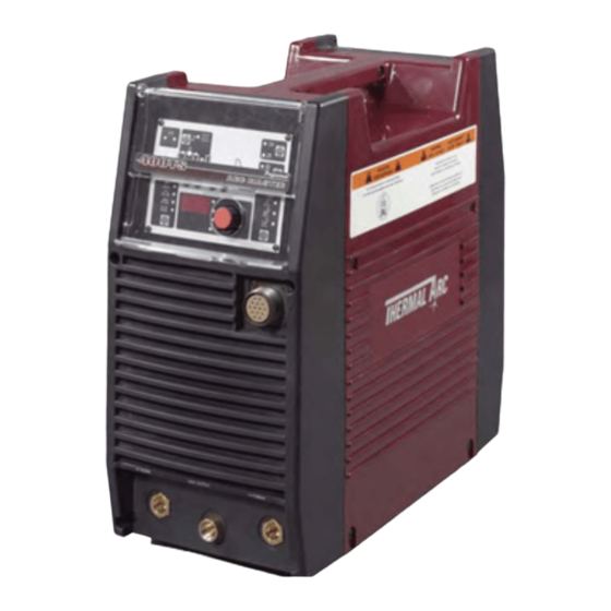
400TS 400S ARCMASTER ® INVERTER ARC WELDERS 300TS 300S Art # A-07263 Service Manual V V V V V ersion No: ersion No: ersion No: ersion No: AA.03 ersion No: Issue Date: Issue Date: Issue Date: Issue Date: Issue Date: May 22, 2006 Manual No Manual No Manual No: 0-4895B... - Page 3 Part Number 10-3071 ArcMaster 400S Inverter Arc Welder Part Number 10-3070 ArcMaster 300TS Inverter Arc Welder Part Number 10-3096 ArcMaster 300S Inverter Arc Welder Part Number 10-3093 Published by: Thermadyne Inc. 82 Benning Street West Lebanon, New Hampshire, USA 03784 (603) 298-5711 www.thermalarc.com...
-
Page 4: Table Of Contents
C O N TE N TS 1 SA FETY I N STR U C TI O N S A N D W A R N I N G S 1 Arc Welding Hazards................1–1 2 PRINCIPAL SAFETY STANDARDS . - Page 5 8 B A SI C TR O U B LESH O O TI N G 1 TIG Welding Problems ................8–1 2 Stick Welding Problems .
- Page 6 C O N TE N TS 3. 7 PCB8, PCB9 (WK-5479) and Q1-Q12 “Primary IGBT” ..........12–12 3.
-
Page 7: Safety Instructions And Warnings
ARCMASTER 400TS, 400S, 300TS, 300S SECTION 1: SAFETY INSTRUCTIONS AND WARNINGS WARNING PROTECT YOURSELF AND OTHERS FROM POSSIBLE SERIOUS INJURY OR DEATH. KEEP CHILDREN AWAY. PACEMAKER WEARERS KEEP AWAY UNTIL CONSULTING YOUR DOCTOR. DO NOT LOSE THESE INSTRUCTIONS. READ OPERATING/INSTRUCTION MANUAL BEFORE INSTALLING, OPERATING OR SERVICING THIS EQUIPMENT. Welding products and welding processes can cause serious injury or death, or damage to other equipment or property, if the operator does not strictly observe all safety rules and take precautionary actions. - Page 8 ARCMASTER 400TS, 400S, 300TS, 300S 11. Do not touch electrode while in contact with the work 4. Wear protective clothing made from durable, flame- (ground) circuit. resistant material (wool and leather) and foot protection. 12. Use only well-maintained equipment. Repair or replace damaged parts at once.
- Page 9 ARCMASTER 400TS, 400S, 300TS, 300S 6. Do not weld in locations near degreasing, cleaning, or spraying operations. The heat and rays of the arc can WARNING react with vapors to form highly toxic and irritating gases. FLYING SPARKS AND HOT METAL can cause 7.
- Page 10 ARCMASTER 400TS, 400S, 300TS, 300S 4. To prevent accidental starting during servicing, disconnect negative (-) battery cable from battery. WARNING 5. Keep hands, hair, loose clothing, and tools away from moving parts. Engines can be dangerous. 6. Reinstall panels or guards and close doors when servicing is finished and before starting engine.
-
Page 11: Principal Safety Standards
ARCMASTER 400TS, 400S, 300TS, 300S 1.02 Principal Safety Standards WARNING Safety in Welding and Cutting, ANSI Standard Z49.1, from American Welding Society, 550 N.W. LeJeune Rd., Miami, This product, when used for welding or FL 33126. cutting, produces fumes or gases which contain chemicals know to the State of Safety and Health Standards, OSHA 29 CFR 1910, from California to cause birth defects and, in some... -
Page 12: Precautions De Securite En Soundage A L'arc
ARCMASTER 400TS, 400S, 300TS, 300S 1.03 Precautions de Securite en Soudage à L’Arc MISE EN GARDE LE SOUDAGE A L’ARC EST DANGEREUX PROTEGEZ-VOUS, AINSI QUE LES AUTRES, CONTRE LES BLESSURES GRAVES POSSIBLES OU LA MORT. NE LAISSEZ PAS LES ENFANTS S’APPROCHER, NI LES PORTEURS DE STIMULATEUR CARDIAQUE (A MOINS QU’ILS N’AIENT CONSULTE UN MEDECIN). - Page 13 ARCMASTER 400TS, 400S, 300TS, 300S 9. N’enroulez pas de câbles électriques autour de votre 1. Portez une casque de soudeur avec filtre oculaire de corps. nuance appropriée (consultez la norme ANSI Z49 indiquée ci-après) pour vous protéger le visage et les 10.
- Page 14 ARCMASTER 400TS, 400S, 300TS, 300S 1. Eloignez la tête des fumées pour éviter de les respirer. 1. Protégez-vous, ainsi que les autres, contre les étincelles et du métal chaud. 2. A l’intérieur, assurez-vous que l’aire de soudage est bien ventilée ou que les fumées et les vapeurs sont 2.
- Page 15 ARCMASTER 400TS, 400S, 300TS, 300S 1. Utilisez l’équipement à l’extérieur dans des aires ouvertes et bien ventilées. AVERTISSEMENT 2. Si vous utilisez ces équipements dans un endroit confiné, les fumées d’échappement doivent être envoyées à l’extérieur, loin des prises d’air du bâtiment. LES BOUTEILLES ENDOMMAGEES PEUVENT EXPLOSER AVERTISSEMENT...
-
Page 16: Principales Normes De Securite
ARCMASTER 400TS, 400S, 300TS, 300S 4. Pour empêcher un démarrage accidentel pendant l’entretien, débranchez le câble d’accumulateur à la borne négative. AVERTISSEMENT 5. N’approchez pas les mains ou les cheveux de pièces en mouvement; elles peuvent aussi accrocher des vêtements amples et des outils. VAPEUR LIQUIDE REFROIDISSEMENT BRULANT SOUS... -
Page 17: N Tr O D U C Ti O N
Electronic copies of this manual can also be down- loaded at no charge in Acrobat PDF format by going to the Thermal Arc web site listed below and clicking on the Literature Library link: http://www.thermalarc.com... -
Page 18: Symbol Chart
300/400TS and 300/400S INTRODUCTION Symbol Chart Note that only some of these symbols will appear on your model. STICK Amperage (Shielded Metal Arc SMAW) Pulse Current Function Voltage Spot Time (GTAW) Hertz (frequency) Remote Control Seconds (Panel/Remote) Remote Function Percent Arc Control (SMAW) DC (Direct Current) Gas Post-Flow... -
Page 19: Description
The Thermal Arc Model ARCMASTER 300S and 400S is a self contained single/three-phase DC arc weld- ing power source with Constant Current (CC) output characteristics. This unit is equipped with a Digital Volt/ Amperage Meter and lift arc starter for use with Gas Tungsten Arc Welding (GTAW) and Shielded Metal Arc Welding (SMAW) processes. -
Page 20: Functional Block Diagrams
300/ 400TS and 300/ 400S I N TR O D U C TI O N Funct i onal B l ock D i agram s Figure 2-2 illustrates the functional block diagram of the 300TS and 400TS power supply. Figure 2-3 illus- trates the functional block diagram of the 300S and 400S power supply. -
Page 21: Transporting Methods
300/ 400TS and 300/ 400S I N TR O D U C TI O N Tr ansport i ng M et hods These units are equipped with a handle for carrying purposes. W A R N I N G ELEC TR I C SH O C K can ki l l . DO NOT TOUCH live electrical parts. - Page 22 300/ 400TS and 300/ 400S I N TR O D U C TI O N PA G E LEFT I N TEN TI O N A LLY B LA N K 2 – 6...
-
Page 23: N Sta Lla Ti O N
I N STA LLA TI O N I N STA LLA TI O N Envi ronm ent El ect ri cal I nput C onnec- t i ons The ARC MASTER 300/400TS and 300/400S are designed for use in adverse environments. Examples of environments with increased adverse W A R N I N G conditions are:... -
Page 24: Input Power
Figure 3-1: Electrical Input Connections The ARC MASTER 300/400TS and 300/400S are designed for use with a generator as an input power source. Contact an accredited Thermal Arc Input Power service agent for the proper sizing and set-up rec- ommendations of a generator power source sys- Each unit incorporates an INRUSH circuit and input tem. -
Page 25: High Frequency Introduction (300/400Ts Only)
300/ 400TS and 300/ 400S I N STA LLA TI O N 3. R adi at i on f r om W el di ng Leads: Radiated H i gh Frequency I nt roduc- interference from welding leads, although pro- t i on ( 300/ 400TS onl y) nounced in the vicinity of the leads, diminishes rapidly with distance. -
Page 26: Specifications
460V I nput Vol t s Si ngl e Phase 208V 230V Thermal Arc continuously strives to produce the the following; variations or changes in manufac- best product possible and therefore reserves the tured components, installation location and condi- right to change, improve or revise the specifica- tions and local power grid supply conditions. -
Page 27: Per A To R C O N Tr O Ls
O PER A TO R C O N TR O LS O PER A TO R C O N TR O LS A R C M A STER 300/ 400TS and 300/ 400S C ont rol s 1. C ont r ol K nob: This control sets the selected weld parameter, rotating it clockwise increases the parameter that is indicated on the digital meter. - Page 28 300/ 400TS and 300/ 400S O PER A TO R C O N TR O LS 3. Posi t i ve Ter m i nal : Welding current flows from W el d Process sel ect i on f or the Power Source via heavy duty Dinse type A R C M A STER 300/ 400TS terminal (50 mm).
-
Page 29: Weld Parameter Descriptions For Arc Master 300/400Ts And 300/400S
300/ 400TS and 300/ 400S O PER A TO R C O N TR O LS W el d Param et er D escri pt i ons f or A R C M A STER 300/ 400TS and 300/ 400S Fi gur e4-3: A RC M A STER 300/ 400TS Fr ont Panel w i t h Par am et er Descr i pt i on... - Page 30 300/ 400TS and 300/ 400S O PER A TO R C O N TR O LS Parameter Description POST-FLOW This parameter operates in TIG modes only and is used to adjust the post gas flow time once the arc has extinguished. This control is used to dramatically reduce oxidation of the tungsten electrode.
-
Page 31: Weld Parameters For Arc Master 300/400Ts And 300/400S
300/ 400TS and 300/ 400S O PER A TO R C O N TR O LS W el d Param et ers f or A R C M A STER 300/ 400TS and 300/ 400S Weld Mode Parameter Weld Parameter Factory Setting Incremental Unit STICK... -
Page 32: Power Source Features
300/ 400TS and 300/ 400S O PER A TO R C O N TR O LS Pow er Sour ce Feat ures Feature Description Feature Description Self An error code is displayed on the Almost all welding parameters are New Digital Diagnosis Digital Meter when a problem adjustable. -
Page 33: Set-Up For Smaw (Stick) And Gtaw (Tig)
SET-UP FOR SMAW (STICK) AND GTAW (TIG) Conventional operating procedures apply when using the Welding Power Source, i.e. connect work lead directly to work piece and electrode lead is used to hold electrode. Wide safety margins pro- vided by the coil design ensure that the Welding Power Source will withstand short-term overload without adverse effects. - Page 34 300/ 400TS and 300/ 400S SET- U P FO R SM A W ( STI C K ) A N D G TA W ( TI G ) PA G E LEFT I N TEN TI O N A LLY B LA N K 5 –...
-
Page 35: Seq U En C E O F O Per A Ti O N
SEQ U EN C E O F O PER A TI O N 4. D i gi t al LED di spl ay: SEQ U EN C E O F O PER A TI O N N O TE Welding amperage and parameter values are Scr ol l But t ons ar e used t o sel ect t he par am et er s t o displayed in this window. -
Page 36: Hf Tig Welding (300/400Ts Only)
300/ 400TS and 300/ 400S SEQ U EN C E O F O PER A TI O N H F TI G W el di ng Sl ope M ode Sequence ( 300/ 400TS onl y) ( 300/ 400TS onl y) Connect work lead to positive terminal. -
Page 37: Slope Mode With Repeat Sequence (300/400Ts Only)
300/ 400TS and 300/ 400S SEQ U EN C E O F O PER A TI O N increase and decrease the welding current on a Sl ope M ode w i t h repeat regular basis. The faster you move the foot rheo- sequence stat up and down, the faster the frequency. - Page 38 300/ 400TS and 300/ 400S SEQ U EN C E O F O PER A TI O N PA G E LEFT I N TEN TI O N A LLY B LA N K 6 – 4...
-
Page 39: O U Ti N E M A I N Ten A N C E
R O U TI N E M A I N TEN A N C E R O U TI N E M A I N TEN A N C E The only routine maintenance required for the power supply is a thorough cleaning and inspec- tion, with the frequency depending on the usage and the operating environment. - Page 40 6 Months Bring the unit to an authorized Thermal Arc Service Center to remove any accumulated dirt and dust from the interior. This may need to be done more frequently under exceptionally dirty conditions.
-
Page 41: A Si C Tr O U B Lesh O O Ti N G
If major complex subassemblies are faulty, then the Welding Power Source must be returned to an Accred- ited Thermal Arc Service Agent for repair. The basic level of troubleshooting is that which can be performed without special equipment or knowledge. - Page 42 300/ 400TS and 300/ 400S B A SI C TR O U B LESH O O TI N G 9. Poor weld finish. Inadequate shielding gas. Increase gas flow or check gas line for gas flow problems. 10.Arc flutters during TIG welding. A.
-
Page 43: Stick Welding Problems
300/ 400TS and 300/ 400S B A SI C TR O U B LESH O O TI N G St i ck W el di ng Probl em s Description Possible Cause Remedy 1. Gas pockets or voids in weld A. - Page 44 300/ 400TS and 300/ 400S B A SI C TR O U B LESH O O TI N G Description Possible Cause Remedy 5. Non-metallic particles are trapped A. Non-metallic particles may be A. If bad undercut is present, clean in the weld metal (slag inclusion).
-
Page 45: Power Source Problems
B. The Welding Power Source switch B. Switch ON the Welding Power is switched OFF. Source. C. Loose connections internally. C. Have an Accredited Thermal Arc Service Agent repair the connection. 2. Maximum output welding current Defective control circuit. Have an Accredited Thermal Arc can not be achieved with nominal Service Agent repair the connection. - Page 46 300/ 400TS and 300/ 400S B A SI C TR O U B LESH O O TI N G PA G E LEFT I N TEN TI O N A LLY B LA N K 8 – 6...
-
Page 47: Voltage Reduction Device (Vrd)
In addition to the above tests and specifically in relation to the VRD fitted to this machine, the fol- lowing periodic tests should also be conducted by an accredited Thermal Arc service agent. Description IEC 60974-1 Requirements VRD Open Less than 20V;... -
Page 48: Switching Vrd On/Off
300/ 400TS and 300/ 400S Vol t age R educt i on D evi ce ( VR D ) C) Access the VRD control by gently prying back Sw i t chi ng VR D O n/ O f f the front panel controls to reveal the VRD on/ off potentiometer (see Figure 9-3). -
Page 49: Po W Er So U R C E Er R O R C O D E
E01 resets when TH1 B. Fan ceases to operate. B. Have an Accredited about 1 second. decreases to 70 C for about Thermal Arc Service 30 seconds. Agent investigate. C. Air flow is restricted by C. Unblock vents then let vents being blocked. - Page 50 E99 error. B. Mains supply (input) B. Have an Accredited power from the primary voltage has been turned Thermal Arc Service capacitors. off. Agent or a qualified electrician check the Mains voltage and fuses.
-
Page 51: D Va N C Ed Tr O U B Lesh O O Ti N G
Service Manual, the subas- sembly should be replaced with a new one. The faulty subassembly should then be returned to Thermal Arc through established procedures. Fi gur e 11-1: Sw i t ch O FF W A R N I N G... - Page 52 300/ 400TS and 300/ 400S A D VA N C ED TR O U B LESH O O TI N G 2) Remove all screws and nuts on the side cov- 4) Pull the front panel slightly forward and pull the ers.
-
Page 53: Verification And Remedy To The Indicated Error Codes
300/ 400TS and 300/ 400S A D VA N C ED TR O U B LESH O O TI N G 6) Remove protection cover sheet by removing 2. 1 E01 "O ver - Tem per at ur e at the plastic tabs. -
Page 54: E02 "Over-Temperature At The Secondary Side
300/ 400TS and 300/ 400S A D VA N C ED TR O U B LESH O O TI N G 2. 2 E02 "O ver - Tem per at ur e at 2. 3 E03 "Tr ansf or m er Over-Curr ent Fai l ur e"... -
Page 55: E04 "Torch Cable Failure
300/ 400TS and 300/ 400S A D VA N C ED TR O U B LESH O O TI N G 2. 4 E04 "Tor ch C abl e Fai l ur e" 2. 6 E12 "M ai n Suppl y U nder Vol t - age"... -
Page 56: E82 "Rated Voltage Selection Circuit Abnormality
300/ 400TS and 300/ 400S A D VA N C ED TR O U B LESH O O TI N G c) Verify PCB4 (WK-4819) and replace it if neces- 2. 8 E82 "R at ed Vol t age Sel ect i on sary. -
Page 57: E94 "Thermistor Malfunction
300/ 400TS and 300/ 400S A D VA N C ED TR O U B LESH O O TI N G 2. 11 E94 "Ther m i st or m al f unct i on" Veri f i cat i on and R em edy t o Fai l ures w i t hout I ndi cat i on C ause C odes... -
Page 58: Gas Valve Failure" (No Gas Flow Through Unit)(300/400Ts Only)
300/ 400TS and 300/ 400S A D VA N C ED TR O U B LESH O O TI N G 3. 2 "G as Val ve Fai l ur e" ( N o G as 3. 3 "N o W el d O ut put " f l ow t hr ough uni t ) When in High Frequency TIG (HF TIG) mode, if the ( 300/ 400TS onl y) -
Page 59: Operating Panel Failure" (Led's Do Not Light Properly Or Welding Setting Cannot Be Established.)
300/ 400TS and 300/ 400S A D VA N C ED TR O U B LESH O O TI N G c) Verify the no-load voltage (OCV). b) Verify the connection between PCB6 (Applies to STICK, High Frequency TIG [HF (WK-5549) and PCB12 (WK-5527). -
Page 60: Fault Isolation Tests
300/ 400TS and 300/ 400S A D VA N C ED TR O U B LESH O O TI N G b) Verify the connection between High Frequency Faul t I sol at i on Test s Unit (HF UNIT1) and the current limiting resistor (R2). -
Page 61: Verification Of The Power Input Circuitry
300/400TS and 300/400S ADVANCED TROUBLESHOOTING Verification of the Power 3) Verify input voltage after the input switch (S1) using an AC voltmeter. (The capability of the Input Circuitry voltmeter should be more than 600VAC.) • Using an AC voltmeter, measure between CAUTION the points U2 and V2 on the input switch, S1. -
Page 62: Verification Of The Power Supply Voltage
ADVANCED TROUBLESHOOTING 2) On the PCB3 (WK-5548) and PCB6 (WK- 6) Verify bus voltage (the voltage of the electrolytic capacitor after rectification) using a 5549), measure the voltages according to the DC Voltmeter. The capacity of the DVM should following table. The check points and the refer- be more than 1000VDC. -
Page 63: Verification Of The Cooling Fan, Fan1, Drive Circuitry
300/ 400TS and 300/ 400S A D VA N C ED TR O U B LESH O O TI N G 3) If any of these voltages are not present or 2) Using the measurement taken above, follow are below a 10% tolerance, replace the the chart below for possible failure modes. -
Page 64: Verification Of The Gas Valve, Sol1, Drive Circuitry
300/ 400TS and 300/ 400S A D VA N C ED TR O U B LESH O O TI N G 5. 4 Ver i f i cat i on of t he G as Val ve, 5. 5 Ver i f i cat i on of t he pr i m ar y SO L1, D r i ve C i r cui t r y D i ode ( D 1) C A U TI O N... -
Page 65: Verification Of The Secondary Diode (D2-D7)
300/ 400TS and 300/ 400S A D VA N C ED TR O U B LESH O O TI N G 1) Check whether there are any abnormalities in 5. 6 Ver i f i cat i on of t he secondar y the appearance of PCB8-PCB11. -
Page 66: Verification Of No-Load Voltage (Ocv)
300/ 400TS and 300/ 400S A D VA N C ED TR O U B LESH O O TI N G 5. 8 Ver i f i cat i on of t he secondar y 5. 9 Ver i f i cat i on of N o- l oad Vol t - I G B T ( Q 25- Q 26) age ( O C V) C A U TI O N... - Page 67 300/400TS and 300/400S ADVANCED TROUBLESHOOTING b. Verify the no-load voltage (OCV) in High Fre- quency TIG mode. WARNING This welding mode produces high frequency and high voltage. Extra care shoul d be taken to prevent electric shock. 1) When in HF TIG mode, the unit will gener- ate high voltage.
-
Page 68: Maintenance List
M A I N TEN A N C E M ai nt enance Li st M A I N TEN A N C E DWG No. Parts name Reference page Part No. 12- 7 W7001313 PCB2 Printed Circuit Board (WK-5597) 12- 9 W7001314 PCB3... - Page 69 300/400TS and 300/400S MAINTENANCE DWG No. Parts name Reference page Part No. Printed Circuit Board (WK-5493) PCB1 12- 6 W7001312 Printed Circuit Board (WK-5549) 300S PCB6 12- 11 W7001730 12- 11 W7001731 Printed Circuit Board (WK-5549) 400S PCB6 12- 11 W7001734 PCB6 Printed Circuit Board (WK-5549) 300TS...
- Page 70 300/ 400TS and 300/ 400S M A I N TEN A N C E DWG No. Parts name Reference page Part No. CON1 Remote Socket 12- 26 W7001666 Primary Diode 12- 28 10-6769 Secondary Diode 12- 28 10-6629 Secondary Diode 12- 28 10-6629 Secondary Diode...
- Page 71 300/400TS and 300/400S MAINTENANCE DWG No. Parts name Reference page Part No. Coupling Coil 12- 20 W7001382 Current Trans 12- 29 W7001304 Current Trans 12- 29 W7001304 FAN1 Cooling Fan 12- 22 W7001307 FCH1 Reactor 12- 20 W7001681 HCT1 Hall Current Sensor 12- 27 10-5003 Ring Core...
-
Page 72: Service Tools
300/ 400TS and 300/ 400S M A I N TEN A N C E Servi ce Tool s 2. 1 Tool s and par t s The tools and parts to be used for maintenance are shown by icons. Long Nose Philips Head Silicon Spanner... -
Page 73: Replacement Procedure
300/ 400TS and 300/ 400S M A I N TEN A N C E R epl acem ent Procedure 3. 1 PC B 1 ( W K - 5493) 1) Remove the Side Panel. [Reference page : 11-1] 2) Remove the PCB2 (WK-5597). [Reference page : 12-7] 3) Remove the Primary Diode (D1). -
Page 74: Pcb2 (Wk-5597)
300/ 400TS and 300/ 400S M A I N TEN A N C E 8) Remove the 18 screws and remove the PCB1 (WK-5493). 3. 2 PC B 2 ( W K - 5597) 1) Remove the Side Panel. [Reference page : 11-1] 2) Remove the screw and then disconnect the four ground terminals. - Page 75 300/ 400TS and 300/ 400S M A I N TEN A N C E 4) Remove the four screws. Remove the PCB3, PCB4, PCB5, PCB6, and PCB7 unit. Disconnect the three connectors. CN13 CN15 CN14 5) Remove the six screws, three terminals and three connectors. 6) Remove the two PCB supporters and then the PCB2 (WK-5597) and insulation sheet.
-
Page 76: Pcb3 (Wk-5548), Pcb7 (Wk-5550)
300/ 400TS and 300/ 400S M A I N TEN A N C E 3. 3 PC B 3 ( W K - 5548) , PC B 7 ( W K - 5550) 1) Remove the Side Panel. [Reference page : 11-1] 2) Remove the PCB4 (WK-4819). -
Page 77: Pcb4 (Wk-4819)
300/ 400TS and 300/ 400S M A I N TEN A N C E 8) Disconnect the one connector and remove the two screws, and then remove the PCB7 (WK-5550) from the PCB3 (WK-5548). Remove one screw and one ground terminal from the PCB7 (WK-5550). CN20 9) Disconnect the two connectors from the PCB3 (WK-5548). -
Page 78: Pcb5 (Wk-5551)
300/ 400TS and 300/ 400S M A I N TEN A N C E 3. 5 PC B 5 ( W K - 5551) 1) Remove the side cover. [Reference page : 11-1] 2) Remove the PCB6 (WK-5549). [Reference page : 12-11] 3) Remove the two screws and three connectors. -
Page 79: Pcb8, Pcb9 (Wk-5479) And Q1-Q12 "Primary Igbt"
300/ 400TS and 300/ 400S M A I N TEN A N C E 3. 7 PC B 8, PC B 9 ( W K - 5479) and Q 1- Q 12 “Pr i m ar y I G B T” 1) Remove the side cover. -
Page 80: Pcb13 (Wk-5528)
300/ 400TS and 300/ 400S M A I N TEN A N C E When reinstalling the PCB12 (WK-5527), engage two latches of Front Control Cover first. 3. 10 PC B 13 ( W K - 5528) 1) Remove the side cover. [Reference page : 11-1] 2) Remove the Protection Cover. -
Page 81: Pcb14 (Wk-5594)
300/ 400TS and 300/ 400S M A I N TEN A N C E 4) Disconnect the one connector from the PCB12 (WK-5527). Remove the nut, washer and terminal. Remove the four screws. Pull out the Operation Panel and bring it down. 5) Remove the one connector and two screws. - Page 82 300/ 400TS and 300/ 400S M A I N TEN A N C E 6) Remove the Nylon Hose and two terminals of SOL1. Remove the four screws and open the Rear Panel. 7) Remove the four screws from the PCB1 (WK-5477). Remove the seven terminals. The cables are drawn out.
-
Page 83: Pcb15 (Wk-5606)
300/ 400TS and 300/ 400S M A I N TEN A N C E 3. 12 PC B 15 ( W K - 5606) 1) Remove the Side Panel. [Reference page : 11-1] 2) Remove the Nylon Hose and two terminals of SOL1. 3) Open the Dust sheet. -
Page 84: Pcb21 (Wk-4917)
300/ 400TS and 300/ 400S M A I N TEN A N C E 3. 14 PC B 21 ( W K - 4917) 1) Remove the Side Panel. [Reference page : 11-1] 2) Remove the six screws from the S1 and remove the six terminals. 3) Remove the four screws and then open the Rear Board. -
Page 85: Current Limiting Resistor (R6)
300/ 400TS and 300/ 400S M A I N TEN A N C E 5) Remove the three screws and the S1 Bus Bar from the PCB21 (WK-4917). 3. 15 C ur r ent Li m i t i ng R esi st or ( R 6) 1) Remove the Side Panel. -
Page 86: Resistor (R7, R8)
300/ 400TS and 300/ 400S M A I N TEN A N C E 3. 16 R esi st or ( R 7, R 8) 1) Remove the Side Panel. [Reference page : 11-1] 2) Remove the main ON/OFF switch (S1). [Reference page : 12-24] 3) Remove the four screws and four terminals. -
Page 87: Coupling Coil (Cc1) 300/400Ts Only
300/ 400TS and 300/ 400S M A I N TEN A N C E 3. 17 C oupl i ng C oi l ( C C 1) 300/ 400TS onl y 1) Remove the side cover. [Reference page : 11-1] 2) Remove the Nylon Hose. -
Page 88: Primary Thermistor (Th1)
300/ 400TS and 300/ 400S M A I N TEN A N C E 3) Remove one screw, one nut and two terminals. Remove one screw, one nut and one terminal. 4) Remove four screws and remove the Reactor (FCH1). 3. -
Page 89: Secondary Thermistor (Th2)
300/ 400TS and 300/ 400S M A I N TEN A N C E 3. 20 Secondar y Ther m i st or ( TH 2) 1) Remove the Side Panel. [Reference page : 11-1] 2) Remove the PCB16 (WK-5569). [Reference page : 12-16] 3) Cut the three snap bands and disconnect the one connector CN9 on the PCB6. -
Page 90: Solenoid Valve (Sol1) 300/400Ts Only
300/ 400TS and 300/ 400S M A I N TEN A N C E 3) Cut the one snap band and disconnect the one connector CN11 on the PCB3. CN11 4) Remove the two screws and detach the Cooling Fan (FAN1). Be sure that the fan is in the correct direction when reinstalling. -
Page 91: Main On/Off Switch (S1)
300/ 400TS and 300/ 400S M A I N TEN A N C E 3) Remove the C-ring and detach the Solenoid Valve (SOL1). When reinstalling, make sure that the C-ring seats in the Solenoid Valve groove. 3. 23 M ai n O N / O FF Sw i t ch ( S1) 1) Remove the Side Panel. -
Page 92: Input Voltage Switch (S2)
300/ 400TS and 300/ 400S M A I N TEN A N C E 3. 24 I nput Vol t age Sw i t ch ( S2) 1) Remove the Side Panel. [Reference page : 11-1] 2) Remove the six screws and six terminals. 3) Remove the four screws, and open the Rear Board. -
Page 93: Remote Socket (Con1)
300/ 400TS and 300/ 400S M A I N TEN A N C E 3. 25 R em ot e Socket ( C O N 1) 1) Remove the Side Panel. [Reference page : 11-1] 2) Remove the Ring Core (L105). [Reference page : 12-30] 3) Disconnect the three connectors CNB-15 on the PCB7. -
Page 94: Hall Current Sensor (Hct1)
300/ 400TS and 300/ 400S M A I N TEN A N C E 3) Remove the two screws and detach the High Frequency Unit (HF. UNIT1). 3. 27 H al l C ur r ent Sensor ( H C T1) 1) Remove the Side cover. -
Page 95: Primary Diode (D1)
300/ 400TS and 300/ 400S M A I N TEN A N C E 3. 28 Pr i m ar y D i ode ( D 1) 1) Remove the Side Panel. [Reference page : 11-1] 2) Remove the PCB3 (WK-5548). [Reference page : 12-9] 3) Remove the six screws and 13 terminals. -
Page 96: Current Trans (Ct2, Ct3)
300/ 400TS and 300/ 400S M A I N TEN A N C E 4) Remove the eight screws and then detach the Secondary Diodes (D2, D4, D5, D7). Be sure that the diodes are placed in the correct direction when reinstalling. Before installing a new diodes, apply a uniform coat of silicone compound (Shinetsu Silicone G-747 or equivalent) on the base. -
Page 97: Ring Core (L1)
300/ 400TS and 300/ 400S M A I N TEN A N C E 3. 31 R i ng C or e ( L1) 1) Remove the Side Panel. [Reference page : 11-1] 2) Remove the Nylon Hose and two terminals. Remove the four screws and open the Rear Panel. 3) Remove the two screws and two terminals. - Page 98 300/ 400TS and 300/ 400S M A I N TEN A N C E 3) Remove the four screws. Pull out the Operation Panel and bring it down. 4) Cut the snap band remove the Ring Core (L105). 12 – 31...
- Page 99 THIS PAGE LEFT INTENTIONALLY BLANK...
-
Page 100: Appendix 1 Parts List
APPENDIX 1 PARTS LIST Equipment Identification All identification numbers as described in the Introduction chapter must be furnished when ordering parts or making inquiries. This information is usually found on the nameplate attached to the equipment. Be sure to include any dash numbers following the Part or Assembly numbers. How To Use This Parts List The Parts List is a combination of an illustration and a corresponding list of parts which contains a break- down of the equipment into assemblies, subassemblies, and detail parts. - Page 101 300/400TS and 300/400S PARTS LIST DWG No. Part No. Description Additi onal Information QTY. MHS20A101KI 20W 100 W7001451 Resistor, gen 3.1, IPS R7-8 MHS20A151JI 20W 150OHM W7001325 Resistor, gen 3.1, IPS DCP-103SR100C-480V 3P-480V 10-6857 Switch, gen 3.1, IPS SDKGA4-A-1-A 10-5222 Switch, gen 3.1, IPS SOL1 5505NBR1.5 DC24V 11VA/10W (with Gas Inlet and PC4-02)
- Page 102 300/400TS and 300/400S PARTS LIST DWG No. Part No. Description Additi onal Information QTY. EDA047300 W7001367 Bus Bar, T-CC, gen 3.1, IPS ECA867900 W7001368 Post, Output, gen 3.1, IPS E1B872000 W7001369 Insulated Board, gen 3.1, IPS E1B859700 W7001370 Insulation Sheet, gen 3.1, IPS EDA079800 W7001371 Insulation Sheet, gen 3.1, IPS...
- Page 103 300/400TS and 300/400S PARTS LIST 300/400TS 4 84...
- Page 104 300/400TS and 300/400S PARTS LIST 300/400S No. DWG No. Part No. Description Additional Information QTY. CON1 MS3102A20-27S(NIC) 14P (with wiring assembly) W7001666 Socket, Remote, gen 3.1, IPS CT2-3 F2A503001 CT 1:40 W7001304 Transformer, gen 3.1, IPS DFA100BA160 10-6769 Diode, gen 3.1, IPS D2,4,5,7 10-6629 Diode, gen 3.1, IPS...
- Page 105 300/400TS and 300/400S PARTS LIST No. DWG No. Part No. Description Additional Information QTY. N4A146500 W7001342 Label, Switch, gen 3.1, IPS N4A598700 W7001511 Label, VRD, gen 3.1, IPS TRAK-BE35-70S 10-6660 Terminal, Output, gen 3.1, IPS Cable, Input, gen 3.1, IPS SOOW AWG8X4C L=3.4m EBA156800 10-6795...
- Page 106 300/ 400TS and 300/ 400S PA R TS LI ST...
- Page 107 300/ 400TS and 300/ 400S PA R TS LI ST 3 74...
-
Page 108: A Ppen D I X 2 C O N N Ec Ti O N W I R I N G G U I D E
A PPEN D I X 2 C O N N EC TI O N W I R I N G G U I D E C O NN EC TI O N W I RI NG G UI DE A PPEN D I X 2 C onnect i on W i ri ng G ui de Destination PCB2 PCB4... - Page 109 300/ 400TS and 300/ 400S C O N N EC TI O N W I R I N G G U I D E CN17 CN21 PCB6 CN20 PCB21 PCB13 PCB12 PCB4 CN22 CN23 PCB10 CN33 CN11 PCB11 FAN1 PCB3 PCB7 CN13 CN18...
-
Page 110: Appendix 3 Interconnect Diagram
APPENDIX 3 INTERCONNECT DIAGRAM INTERCONNECT DIAGRAM APPENDIX 3 INTERCONNECT DIAGRAM 300/400TS TB13 TB10 TB14 TB11 PCB8 PCB10 TB15 TB12 PCB1 IGBT IGBT K(7) Main Gate Gate Circuit G(6) Circuit Circuit Board Board Board [WK-5493] R(3) Line1 [WK-5479] [WK-5479] S(4) Line2 T(5) Line3 Ground... - Page 111 300/400TS and 300/400S INTERCONNECT DIAGRAM PCB15 DIODE Snubber Circuit Board [WK-5606] PCB14 TRANS Board 1 2 3 [WK-5594] TB35 +Output Terminal TB33 HCT1 TB21 TB34 TB30 TB16 1 2 3 4 5 Ground TB32 RY+15V PCB20 Filter Circuit /RY_ON Board SIDE CHASSIS 3 TB22 [WK-5499]...
- Page 112 300/ 400TS and 300/ 400S I N TER C O N N EC T D I A G R A M 300/400S TB13 TB10 TB14 TB11 PCB8 PCB10 TB15 TB12 PCB1 IGBT IGBT K(7) Main Gate Gate Circuit G(6) Circuit Circuit Board Board...
- Page 113 300/ 400TS and 300/ 400S I N TER C O N N EC T D I A G R A M PCB15 DIODE Snubber Circuit Board [WK-5606] PCB14 TRANS Board 1 2 3 [WK-5594] TB35 +Output Terminal TB33 HCT1 TB21 TB34 TB30 TB16...
- Page 114 A PPEN D I X 4 D I O D E TESTI N G B A SI C S D I O D E TESTI N G B ASI C A PP EN D I X 4 D I O D E Test i ng B asi c Testing of diode modules requires a digital Volt/ Ohmmeter that has a diode test scale.
-
Page 116: Limited Warranty
No employee, agent, or representative of Thermal Arc is authorized to change this warranty in any way or grant any other warranty, and Thermal Arc shall not be bound by any such attempt. -
Page 117: Warranty Schedule
WARRANTY SCHEDULE This information applies to Thermal Arc products that were purchased in the USA and Canada. April 2006 ENGINE DRIVEN WELDERS ARRANTY ERIOD ABOR Scout, Raider, Explorer Original Main Power Stators and Inductors .................. 3 years 3 years Original Main Power Rectifiers, Control P.C. Boards ..............3 years... -
Page 119: Global Customer Service Contact Information
GLOBAL CUSTOMER SERVICE CONTACT INFORMATION Thermadyne Asia Sdn Bhd Thermadyne USA Lot 151, Jalan Industri 3/5A 2800 Airport Road Rawang Integrated Industrial Park - Jln Batu Arang Denton, Tx 76207 USA 48000 Rawang Selangor Darul Ehsan Telephone: (940) 566-2000 800-426-1888 West Malaysia Fax: 800-535-0557 Telephone: 603+ 6092 2988... - Page 120 World Headquarters Thermadyne Holdings Corporation Suite 300, 16052 Swingley Ridge Road St. Louis, MO 63017 Telephone: (636) 728-3000 Fascimile: (636) 728-3010 Email: sales@thermalarc.com www.thermalarc.com...
Need help?
Do you have a question about the ARCMASTER 300S and is the answer not in the manual?
Questions and answers