
Related Manuals for Thermal Arc 300GTSW Pro-Wave


Summary of Contents for Thermal Arc 300GTSW Pro-Wave
-
Page 1: Service Manual
300GtSw pro-wave Inverter arc welder Art # A-06102 Service Manual Version No: AB Issue Date: June 21, 2012 Manual No.: 0-2515 Operating Features:... - Page 2 WE APPRECIATE YOUR BUSINESS! Congratulations on your new Thermal Arc product. We are proud to have you as our customer and will strive to provide you with the best service and reliability in the industry. This product is backed by our extensive warranty and world-wide service network.
- Page 3 WARNINGS Read and understand this entire Manual and your employer’s safety practices before installing, operating, or servicing the equipment. While the information contained in this Manual represents the Manufacturer's best judgement, the Manufacturer assumes no liability for its use. Pro-Wavel 300GTSW Inverter Arc Welder Service Manual Number 0-2515 for: 208/230VAC Single-Voltage, Single-/Three-Phase Spec Number: 10-3024...
-
Page 4: Table Of Contents
TABLE OF CONTENTS SECTION 1: SAFETY INSTRUCTIONS AND WARNINGS ............1-1 1.01 Arc Welding Hazards ..................1-1 1.02 PRINCIPAL SAFETY STANDARDS ..............1-5 1.03 PRECAUTIONS DE SECURITE EN SOUDAGE A L’ARC ........1-6 1.04 Dangers relatifs au soudage à l’arc ..............1-6 1.05 PRINCIPALES NORMES DE SECURITE ............ - Page 5 TABLE OF CONTENTS (continued) TABLE OF CONTENTS 6.08 High Frequency (HF) START Circuit Test ............6-7 6.09 Subsystem Test Preparation ................6-8 6.10 Main Circuit Breaker (MCB) Replacement Procedure ........6-8 6.11 Main PCB1 Gate Drive Enable Signal Test ............. 6-10 6.12 Lift Start Test ....................
- Page 6 TABLE OF CONTENTS APPENDIX 1: GENERAL INFORMATION ..............A-1 APPENDIX 2: 208/230VAC SINGLE-VOLTAGE SINGLE-/THREE-PHASE ......A-2 APPENDIX 3: 208/230/460VAC SINGLE-/THREE-PHASE ..........A-4 APPENDIX 4: 380/415VAC SINGLE-VOLTAGE THREE-PHASE ........A-6 APPENDIX 5: WIRE CHART MAIN BOARD PCB1 ............A-8 APPENDIX 6: WIRE CHART FRONT PANEL PCB6 ............A-12 APPENDIX 7: WIRE CHART AC IGBT GATE DRIVE PCB8 ..........A-14 APPENDIX 8: BOTTOM WIRING PLACEMENT DIAGRAM ..........A-15 APPENDIX 9: DIODE TESTING BASICS ..............A-16...
-
Page 7: Safety Instructions And Warnings
pro-wave 300gtsw SECTION 1: SAFETY INSTRUCTIONS AND WARNINGS WARNING PROTECT YOURSELF AND OTHERS FROM POSSIBLE SERIOUS INJURY OR DEATH. KEEP CHILDREN AWAY. PACEMAKER WEARERS KEEP AWAY UNTIL CONSULTING YOUR DOCTOR. DO NOT LOSE THESE INSTRUCTIONS. READ OPERATING/INSTRUCTION MANUAL BEFORE INSTALLING, OPERATING OR SERVICING THIS EQUIPMENT. Welding products and welding processes can cause serious injury or death, or damage to other equipment or property, if the operator does not strictly observe all safety rules and take precautionary actions. - Page 8 pro-wave 300gtsw 13. In confined spaces or damp locations, do not use a welder with AC output unless it is equipped with a voltage reducer. Use equipment with DC output. WARNING 14. Wear a safety harness to prevent falling if working FUMES AND GASES can be hazardous to above floor level.
- Page 9 pro-wave 300gtsw 7. Do not weld on coated metals, such as galvanized, lead, or cadmium plated steel, unless the coating is WARNING removed from the weld area, the area is well ventilated, and if necessary, while wearing an air-supplied FLYING SPARKS AND HOT METAL can cause respirator.
- Page 10 pro-wave 300gtsw 6. Reinstall panels or guards and close doors when servicing is finished and before starting engine. WARNING Engines can be dangerous. WARNING SPARKS can cause BATTERY GASES TO EXPLODE; BATTERY ACID can burn eyes and WARNING skin. ENGINE EXHAUST GASES can kill. Batteries contain acid and generate explosive gases.
-
Page 11: Principal Safety Standards
pro-wave 300gtsw 1.02 PRINCIPAL SAFETY STANDARDS WARNING Safety in Welding and Cutting, ANSI Standard Z49.1, from American Welding Society, 550 N.W. LeJeune Rd., This product, when used for welding or Miami, FL 33126. cutting, produces fumes or gases which contain chemicals know to the State of Safety and Health Standards, OSHA 29 CFR 1910, from California to cause birth defects and, in some Superintendent of Documents, U.S. -
Page 12: Precautions De Securite En Soudage A L'arc
pro-wave 300gtsw 1.03 PRECAUTIONS DE SECURITE EN SOUDAGE A L’ARC MISE EN GARDE LE SOUDAGE A L’ARC EST DANGEREUX PROTEGEZ-VOUS, AINSI QUE LES AUTRES, CONTRE LES BLESSURES GRAVES POSSIBLES OU LA MORT. NE LAISSEZ PAS LES ENFANTS S’APPROCHER, NI LES PORTEURS DE STIMULATEUR CARDIAQUE (A MOINS QU’ILS N’AIENT CONSULTE UN MEDECIN). - Page 13 pro-wave 300gtsw 9. N’enroulez pas de câbles électriques autour de votre corps. 10. N’utilisez qu’une bonne prise de masse pour la mise AVERTISSEMENT à la terre de la pièce à souder. LE RAYONNEMENT DE L’ARC PEUT BRÛLER 11. Ne touchez pas à l’électrode lorsqu’en contact avec le LES YEUX ET LA PEAU;...
- Page 14 pro-wave 300gtsw 1. Protégez-vous, ainsi que les autres, contre les étin- celles et du métal chaud. 2. Ne soudez pas dans un endroit où des particules AVERTISSEMENT volantes ou des projections peuvent atteindre des LES VAPEURS ET LES FUMEES SONT DAN- matériaux inflammables.
- Page 15 pro-wave 300gtsw 2. Si vous utilisez ces équipements dans un endroit con- finé, les fumées d’échappement doivent être envoyées à l’extérieur, loin des prises d’air du bâtiment. AVERTISSEMENT LES BOUTEILLES ENDOMMAGEES PEUVENT EXPLOSER AVERTISSEMENT Les bouteilles contiennent des gaz protecteurs LE CARBURANT PEUR CAUSER UN INCENDIE sous haute pression.
-
Page 16: Principales Normes De Securite
pro-wave 300gtsw 6. Réinstallez les capots ou les protecteurs et fermez les 1.05 PRINCIPALES NORMES DE portes après des travaux d’entretien et avant de faire SECURITE démarrer le moteur. Safety in Welding and Cutting, norme ANSI Z49.1, American Welding Society, 550 N.W. LeJeune Rd., Miami, FL 33128. S a f e t y a n d H e a l t h S t a n d a r d s , O S H A 2 9 C F R 1 9 1 0 , Superintendent of Documents, U.S. -
Page 17: Declaration Of Conformity
pro-wave 300gtsw 1.06 DECLARATION OF CONFORMITY Manufacturer: Victor Technologies Address: 16052 Swingley Ridge Road, Suite 300 Chersterfiedl, MO 63017 The equipment described in this manual conforms to all applicable aspects and regulations of the ‘Low Voltage Direc- tive’ (European Council Directive 73/23/EEC as amended by Council Directive 93/68/EEC) and to the National legislation for the enforcement of this Directive. -
Page 18: Limited Warranty
No employee, agent, or representative of Thermal Arc is authorized to change this warranty in any way or grant any other warranty. -
Page 19: Introduction
Manual number and equipment identification numbers. Electronic copies of this manual can also be downloaded at no charge in Acrobat PDF format by going to the Thermal Arc web site listed below and clicking on the Literature Library link: http://www.thermalarc.com... -
Page 20: Symbol Chart
pro-wave 300gtsw 2.04 Symbol Chart Note that only some of these symbols will appear on your model. Wire Feed Function Single Phase Wire Feed Towards Workpiece With Three Phase Output Voltage Off. Three Phase Static Frequency Converter- Welding Gun Dangerous Voltage Transformer-Rectifier Purging Of Gas Increase/Decrease... -
Page 21: General Description
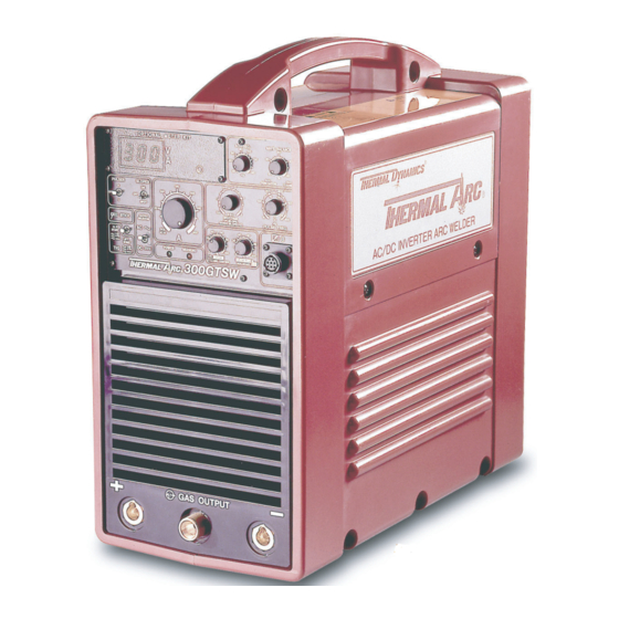
300gtsw 2.05 General Description The Thermal Arc Model 300GTSW is a three-phase or ™ single-phase (if derated) AC/DC arc welding power source with Constant Current (CC) output characteristics. The unit is equipped with a gas control valve, built-in Sloper... -
Page 22: Functional Block Diagram
pro-wave 300gtsw 2.06 Functional Block Diagram Figure 2-2 illustrates the functional block diagram of the 300GTSW power supply. Input Main Current Input Inrush Current IGBT Inverter Output Output Output IGBT Inverter Capacitor Circuit Diode Diodes Suppresor Module Transformers Inductor Module Transformer Power Breaker... -
Page 23: Transporting Methods
pro-wave 300gtsw 2.07 Transporting Methods These units are equipped with a handle for carrying purposes. WARNING ELECTRIC SHOCK can kill. • DO NOT TOUCH live electrical parts. • Disconnect input power conductors from de- energized supply line before moving welding power source. WARNING FALLING EQUIPMENT can cause serious personal injury and equipment damage. -
Page 24: Specifications
pro-wave 300gtsw 2.08 Specifications Parameter 208V/230V/460V Rated Output Three Phase Single Phase Amperes Volts Duty Cycle Output Range (Min. - Max.) TIG/STICK Amperes 5-300 DC or 10-300 AC Volts 10-32 Volts Open Circuit Voltage Maximum OCV 64 V Input Data 50/60 Hz Dimensions/Weight Width... -
Page 25: Duty Cycle
pro-wave 300gtsw 2.09 Duty Cycle The duty cycle of a welding power source is the percentage of a ten (10) minute period that it can be operated at a given output without causing overheating and damage to the unit. If the welding amperes decrease, the duty cycle increases. - Page 26 pro-wave 300gtsw This page left blank intentially June 21, 2012...
-
Page 27: Installation
pro-wave 300gtsw SECTION 3: INSTALLATION 3.01 Electrical Input Connections WARNING ELECTRIC SHOCK can kill; SIGNIFICANT DC VOLTAGE is present after removal of input power. • DO NOT TOUCH live electrical parts. • SHUT DOWN welding power source, disconnect input power employing lockout/tag out procedures. Lockout/tag out procedures consist of padlocking line disconnect switch in open position, removing fuses from fuse box, or shutting off and red-tagging circuit breaker or other disconnecting device. - Page 28 pro-wave 300gtsw 1. Connect end of ground (GREEN) conductor to a suitable ground. Use a grounding method that complies with all applicable electrical codes. 2. Connect ends of line 1 (BLACK), line 2 (WHITE) and line 3 (RED) input conductors to a de-energized line disconnect switch.
-
Page 29: Operation
pro-wave 300gtsw SECTION 4: 8. sloper switch: OPERATION When in the OFF position the Sloper is inactive. Selecting the ON position activates the Sloper. Selecting the SPOT position activates the spot 4.01 Operator Controls welding timer. The Slope sequence and spot modes are activated by a remote ON/OFF switch connected 1. - Page 30 pro-wave 300gtsw 11. wave Balance: sloper sequence: This controls the portion of each AC output cycle A. Remote ON/OFF switch closed: that has its polarity reversed. The reverse polarity Pre-flow starts to flow. In HF TIG mode HF and portion of the waveform is used to clean the oxides initial current is present after pre-flow.
- Page 31 pro-wave 300gtsw 1. primary power switch: Placing the Primary Power Switch (circuit breaker) located on the rear panel to the ON position energizes the welding power source. 2. voltage selector: Manual slide switch selects the proper input voltage range. (208-230/460VAC Model only) 3.
- Page 32 pro-wave 300gtsw This page left blank intentially June 21, 2012...
-
Page 33: Service
pro-wave 300gtsw 5.02 Basic Troubleshooting SECTION 5: SERVICE You should always attempt to isolate and fix a problem using this section first. This section on basic troubleshooting will help you isolate faults and problems that are easily 5.01 Routine Maintenance remedied without requiring that the power supply be opened, or requiring specialized test equipment and The only routine maintenance required for the power... -
Page 34: Specific Problems
pro-wave 300gtsw 5.04 Specific Problems B. WARNING Indicator is ON 1. Unit is in thermal shutdown mode How to Use this guide a. Allow cooling period of approximately five (5) The following information is a guide to help you determine minutes with the power ON. - Page 35 pro-wave 300gtsw D. Wandering Arc, Poor Control of Arc Direction a. Reduce stand-off. 1. Wrong size tungsten electrode, typically larger than 7. Faulty Main Circuit Board (PCB1) recommended a. Refer to the Main Circuit Board section 6.11, a. Use proper size electrode for amperage page 6-10.
- Page 36 pro-wave 300gtsw 3. Thermal sensor TH1 open (thermal shutdown) H. Green AC POWER Indicator OFF; Fan Not Operating a. Allow the unit to cool for five minutes before 1. Input line disconnect switch in OFF position turning the power supply ON. If the problem still occurs, perform the PCA Thermal Sensor a.
- Page 37 pro-wave 300gtsw M. Limited Weld Output O. No Weld Output; Fan Not Operating; WARNING Indicator OFF 1. Poor primary input voltage 1. Line voltage too low a. Check primary input voltageis within ±10% of nominal voltage, i.e. 230VAC ±10%. a. Verify that input voltage matches setting on rear panel INPUT SELECTOR switch.
- Page 38 pro-wave 300gtsw This page left blank intentially June 21, 2012...
-
Page 39: Advanced Troubleshooting
pro-wave 300gtsw SECTION 6: 6.01 System-Level Fault Isolation ADVANCED TROUBLESHOOTING If none of the suggestions provided in Section 5 have solved the problem or corrected the faulty operation, the next step is to isolate one or more of the internal If you are here, all of the troubleshooting suggestions in subassemblies that may be defective. -
Page 40: Opening The Enclosure
pro-wave 300gtsw 6.02 Opening the Enclosure to open the enclosure: 1. Turn off the MAIN CIRCUIT BREAKER (MCB) on the rear of the power supply. 2. Wait at least two minutes to allow the input capacitors to discharge. 3. Remove the two screws on the top and three screws from bottom of the unit. -
Page 41: Easy Link Fault Isolation Test (208-230/460Vac Model Only)
pro-wave 300gtsw 6.04 Easy Link Fault Isolation Test (208- 230/460VAC Model only) The Easy Link circuit configures the internal power circuits to accept the input power. This test verifies that the INPUT SELECT switch is functioning properly, and the Easy Link circuit can detect both the maximum 460 and the minimum 208-230V input power, and correctly configure the internal power circuits for proper operation under both input power conditions. -
Page 42: Power Supply Voltage Test
pro-wave 300gtsw 6.05 Power Supply Voltage Test 12. On the Main Circuit Board (PCB1), measure the voltages between the following points: Refer to figure 6-2. For location of ribbon cables. CN1: Hall Effect 1. Connect the power supply to a source of either Pin 1 and pin 4 +12VDC 208-230VAC or 460VAC. - Page 43 pro-wave 300gtsw CN9 (PCB6) CN8 (PCB6) CN7 (PCB6) Art # A-06111 CN10 CN13 Figure 6-2: Power supply voltage connector locations. June 21, 2012...
-
Page 44: Output Load Test
pro-wave 300gtsw 6.06 Output Load Test 6.07 LIFT START Circuit Test This test verifies that the output controls are functioning This test verifies proper operation of the LIFT START properly. A clamp-type amperage meter or equivalent circuit. A clamp-type amperage meter or equivalent meter meter capable of reading approximately 300A full-scale capable of reading approximately 20A full-scale, and a will be needed for this test if a digital meter is not present... -
Page 45: High Frequency (Hf) Start Circuit Test
pro-wave 300gtsw 12. Place the power supply MCB on the rear of the 6.08 High Frequency (HF) START Circuit unit to the ON position. After five (5) seconds, Test the amperage meter will indicate approximately 17Amps. This test verifies the operation of the HF START circuit. 13. -
Page 46: Subsystem Test Preparation
pro-wave 300gtsw 6.09 Subsystem Test Preparation 6.10 Main Circuit Breaker (MCB) Replacement Procedure The following initial conditions must be met prior to starting any of the procedures in the subsystem tests. 1. Set the PROCESS SELECTOR switch to STICK WARNING mode. - Page 47 pro-wave 300gtsw Retaining Screws Art # A-06112 Figure 6-3: Main Circuit Breaker White Black Art # A-06113 Figure 6-4: Main Circuit Breaker connections - single phase Art # A-06114 Black White Figure 6-5: Main Circuit Breaker connection - three phase June 21, 2012...
-
Page 48: Main Pcb1 Gate Drive Enable Signal Test
pro-wave 300gtsw 6.11 Main PCB1 Gate Drive Enable Signal Test The gate drive signals are 21.3kHz square wave signals, with an OFF level of -4VDC for 26µs, and the ON level of +11VDC for 21µs. There is a 2.5µs dead time before and after the ON time of each channel before the other goes through its OFF/ON transition. - Page 49 pro-wave 300gtsw CN16 Art # A-06115 CN24 Figure 6-6: Main Circuit Board Art # A-06116 10.0µs/div. +11.0V -4.0V +11.0V -4.0V Figure 6-7: Gate drive enable waveform June 21, 2012 6-11...
-
Page 50: Lift Start Test
pro-wave 300gtsw 6.12 Lift Start Test 6.14 High Frequency Test 1. Disconnect primary power at the source. Make 1. Place the PROCESS SELECTOR Switch in the sure the MAIN CIRCUIT BREAKER is in the OFF STICK position. position. 2. Jumper pins 1 and 5 on the CN7 plug. Apply power 2. -
Page 51: Main Circuit Board (Pcb1) Replacement Procedure
pro-wave 300gtsw 6.15 Main Circuit Board (PCB1) Replacement Procedure to remove the Main Circuit Board: 1. Locate connectors CN7, CN8 and CN9 at the top edge of the Front Panel Circuit Board. 2. Gently pull up on the retainer bar on each side of each connector to release the ribbon cable in the connectors. - Page 52 pro-wave 300gtsw 4. On the Main Circuit Board, remove the screw from TB12 and remove the GREEN ground wire lug from the terminal (figure 6-9). Art # A-06117 TB12 Figure 6-9: Location of TB12 on main circuit board 5. Remove all connectors from the left side and front of the Main Circuit Board — CN1 , CN2 , CN4, CN5 , CN7, CN10, CN13 and CN26 (not shown).
- Page 53 pro-wave 300gtsw Art # A-06118 Figure 6-11: Location of TB1 through TB6 on main circuit board 8. Remove the screws securing the MAIN CIRCUIT BREAKER to the rear panel. 9. Remove connectors CN6, CN8, CN9, and CN14 from the rear of the Main Circuit Board. 10.
- Page 54 pro-wave 300gtsw 11. Cut the cable tie securing the CN18-to-CN24 ORANGE/GRAY wire pair to the BLACK lead attached to TB1. 12. Remove the four (4) mounting screws from the corners of the Main Circuit Board. Art # A-06119 Figure 6-13: Main circuit board retaining screws 13.
- Page 55 pro-wave 300gtsw Art # A-06118 Figure 6-14: TB1 through TB6 reconnections June 21, 2012 6-17...
-
Page 56: Gaining Access To Front Panel Circuit Board (Pcb6) Wk-3988
pro-wave 300gtsw 6.16 Gaining Access to Front Panel Circuit Board (PCB6) WK-3988 To gain access to the test points on the Front Panel Circuit Board, it is necessary to remove the front panel of the power supply unit. To accomplish this, do the following: 1. -
Page 57: Front Panel Pcb6 (Wk-3988) Test Point Voltages
pro-wave 300gtsw 6.17 Front Panel PCB6 (WK-3988) Test Point Voltages The test point voltages on the Front Panel Circuit Board should be verified as follows. 1. Set up the contactor closure circuit by installing a jumper between pins 2 and 3 of the REMOTE 8 receptacle; 2. -
Page 58: Input Power Selector Switch Test
pro-wave 300gtsw 6.18 Input Power Selector Switch Test 1. Using an ohmmeter check continuity from CN13 Pin1 and Pin 3 with the input voltage selector switch in the 208/230 volt position. 2. Using an ohmmeter check continuity from CN13 Pin 2 and Pin 3 with the input voltage selector switch in the 460 volt position. - Page 59 pro-wave 300gtsw Art # A-06123 Figure 6-18: Component side of front panel circuit board 5. Remove the Front Panel Circuit Board from the power supply. To replace the Front Panel Circuit Board, reverse the removal steps. June 21, 2012 6-21...
-
Page 60: Current Transformer Test Procedure
pro-wave 300gtsw 6.20 Current Transformer Test Procedure 5. Remove the Output Bus Bar/CT. 6. At the end removed from the POSITIVE (+) 1. Disconnect connector CN1 from the Main Circuit OUTPUT TERMINAL, bend the Output Bus Bar Board (PCB1). sufficiently to allow the CT to slide off the end of 2. -
Page 61: Power Control Assembly
pro-wave 300gtsw 6.22 Power Control Assembly The Power Control Assembly (PCA) consists of input diode (D1), IGBT Inverters (Q1-Q4), output diodes (D2-D5), heat sinks, main and auxiliary transformers, output inductors and high frequency coupling coil. Perform a careful inspection of all components of the PCA first. Failure may be identified by burned insulation or other physical symptoms. If there are no signs of physical damage, conduct the procedure that follows. -
Page 62: Pca Input Diode Bridge (D1) Test Procedure
pro-wave 300gtsw 6.24 PCA Input Diode Bridge (D1) Test 6.25 PCA Input Diode Bridge (D1) Procedure Replacement Procedure Refer to figure 6-21 Refer to figure 6-21. 1. Select the Ohms scale on the digital meter. to remove the Input Diode Bridge (D1), do the following: 2. - Page 63 pro-wave 300gtsw Red Input Line Art # A-06126 R2 (Junction) Thyristor Gate Thyristor Cathode (+) Diode Anode (–) Figure 6-21: Power control assembly - input diode bridge (D1) June 21, 2012 6-25...
-
Page 64: Pca Igbt Inverter Test Procedure
pro-wave 300gtsw 6.26 PCA IGBT Inverter Test Procedure Refer to figures 6-22 and 6-23. The IGBT Inverter sections contain four IGBT transistor/diode assemblies, Q1, Q2, Q3 and Q4. These can be tested with the power OFF to verify their proper function. IGBT Inverter Q2 Auxiliary Transformer (T3) TB2 Primary Lead... - Page 65 pro-wave 300gtsw power oFF test procedure Pin 5 Pin 4 Pin 2 1. Set the diode test scale on the digital meter. Pin 1 Art # A-06128 2. For Q1, check the diodes between: TB3 and TB1 TB4 and TB1 3.
-
Page 66: Pca Igbt Inverters Q1 And Q2 Replacement Procedure
pro-wave 300gtsw 6.27 PCA IGBT Inverters Q1 and Q2 4. Remove the two (2) screws securing the Inverter to the main chassis frame. Replacement Procedure to replace either Inverter (Q1 or Q2), do the Refer to figure 6-26. following: to remove either of the IgBt Inverters Q1 or Q2, do 1. - Page 67 pro-wave 300gtsw THIS PAGE INTENTIONALLY LEFT BLANK June 21, 2012 6-29...
-
Page 68: Pca Igbt Inverter Q3/Q4 Replacement Procedure
pro-wave 300gtsw 6.28 PCA IGBT Inverter Q3/Q4 to replace either Inverter Q3/Q4, do the following: Replacement Procedure 1. Spread a light coating of thermal compound on the bottom surface of the Inverters. Refer to figure 6-27. 2. Reverse the remaining removal steps above. When to remove IgBt Inverters Q3/Q4, do the following. - Page 69 pro-wave 300gtsw Art # A-06127 IGBT's HF Unit Coupling Coil Leads Inverter Q3/Q4 Figure 6-28: IGBT Inverter Q3/Q4 June 21, 2012 6-31...
-
Page 70: Pca Output Diodes (D2-D5) Test Procedure
pro-wave 300gtsw 6.29 PCA Output Diodes (D2-D5) Test Procedure WARNING Disconnect primary power at the source before performing this procedure. Refer to figure 6-29 below. The output section contains four diodes, D2 through D5. Check each diode between its POSITIVE (A) and NEGATIVE (K) TERMINALS. -
Page 71: Pca Output Diodes (D2 - D5) Replacement Procedure
pro-wave 300gtsw 6.30 PCA Output Diodes (D2 - D5) Replacement Procedure to gain access to the output Diodes: The Main Transformers T1 and T2 and their metal mounting brackets must be removed from the chassis. 1. Remove the Output Inductor Assembly refer to section 6.37 page 6-42. 2. - Page 72 pro-wave 300gtsw 3. Remove hardware at Coupling Coil/Bus Bar 8. Remove the two (2) screws securing the output junction. Remove bus bar. (Figure 6-31) diode to the chassis. 4. Remove the compression nut from the gas inlet to replace the output Diodes (D2 -D5), do the fitting on rear panel and move gas line away from following: Main Transformers.
- Page 73 pro-wave 300gtsw T1/T2 Mounting Brackets IGBT Inverter Q3 Art # A-06133 Figure 6-32: Output diodes and T1/T2 mounting brackets Art # A-06134 Figure 6-33: Output diodes D2-D5 June 21, 2012 6-35...
-
Page 74: Pca Thermal Sensor (Th1) Test Procedure
pro-wave 300gtsw 6.31 PCA Thermal Sensor (TH1) Test Procedure WARNING Disconnect primary power at the source before performing this procedure. Refer to figure 6-34. 1. Select the Ohms scale on the digital meter. 2. Disconnect the connector at CN10 on the Main Circuit Board (PCB1). 3. -
Page 75: Thermal Sensor (Th1) Replacement
pro-wave 300gtsw 6.32 Thermal Sensor (TH1) Replacement 4. Cut cable ties as appropriate to free the BLACK/ BLACK wire harness that connects the Thermal Refer to figure 6-35. Sensor to connector CN10 plug. to remove the thermal sensor (tH1), do the to replace the thermal sensor (tH1), do the following: following:... -
Page 76: Auxiliary Transformer (T3) Test Procedure
pro-wave 300gtsw 6.33 Auxiliary Transformer (T3) Test power oFF test Procedure The auxiliary transformer can be checked with either a WARNING power OFF or power ON test. Do the power OFF test first. Disconnect primary power at the source before performing this procedure. -
Page 77: Auxiliary Transformer (T3) Replacement
pro-wave 300gtsw 6.34 Auxiliary Transformer (T3) Replacement Refer to figure 6-36. to remove the auxiliary transformer (t3), do the following: 1. Remove Main Circuit Board, per page 6-13. 2. Remove connector CN1 from PCB8. 3. Remove the RED and WHITE lugged wires from the R and S terminals of the Input Diode Bridge (D1). -
Page 78: Main Transformer Assembly (T1 And T2) Test Procedure
pro-wave 300gtsw 6.35 Main Transformer Assembly (T1 2. To test the primary of T1, measure the continuity between Main Circuit Board connector CN8 pin 2 and T2) Test Procedure and the lugged transformer lead removed from TB1. 3. To test the primary of T2, measure the continuity WARNING between Main Circuit Board connector CN9 pin 2 Disconnect primary power at the source before... -
Page 79: Main Transformer (T1 And T2) Assembly Replacement Procedure
pro-wave 300gtsw 6.36 Main Transformer (T1 and T2) 8. Remove the Output Inductor Assembly section 6.37 page 6-42. Assembly Replacement Procedure 9. Bend the secondary center tap leads of both to remove Main transformer t1 or t2: transformers T1 and T2 (“D)” up to expose the “C”... -
Page 80: Output Inductor Assembly Test And Replacement Procedures
pro-wave 300gtsw 6.37 Output Inductor Assembly Test and replacement procedure Replacement Procedures Refer to Figures 6-40 and 6-41 To remove the Output Inductor Assembly: test procedure 1. Remove the four (4) bolts and hardware from the 1. Inspect the Output Inductor Assembly for signs Output Diode/Inductor Assembly junctions at W, of overheating or loose connections. - Page 81 pro-wave 300gtsw Art # A-06139 Cable ties to cut Figure 6-41: Coupling coil cable ties June 21, 2012 6-43...
-
Page 82: Fan Assembly Replacement Procedure
pro-wave 300gtsw 6.38 Fan Assembly Replacement Procedure Refer to figures 6-42 and 6-43. to remove fan: 1. Remove the Output Inductor Assembly per section 6.37 page 6-42. 2. Remove the bolt inside the POSITIVE (+) OUTPUT TERMINAL and the hardware from the Output Bus Bar/IGBT Inverter Q3/Q4 junction. - Page 83 pro-wave 300gtsw Bolt, Positive (+) Output Output Bus Bar Current Transformer Art # A-06124 Junction Hardware IGBT Inverter Q3 Figure 6-42: Output bus bar/CT assembly IGBT Inverter Q3/Q4 Driver Board CN1 Art # A-06140 R6 Topscrew Fan Assembly Fan Retaining Screw Figure 6-43: Cable ties and R6 on right side of unit June 21, 2012 6-45...
-
Page 84: Hf Unit Test And Replacement Procedures
pro-wave 300gtsw 6.39 HF Unit Test and Replacement Procedures HF Unit test procedure 1. Place the PROCESS SELECTOR Switch in the STICK position. 2. Jumper pins 1 and 5 on the CN7 plug. Apply power to the unit. 3. If the high frequency buzz is heard coming from the HF Unit, the Main Circuit Board (PCB1) should be replaced. - Page 85 pro-wave 300gtsw Art # A-06141 HF Unit AC1/AC2 Coupling Coil Connections Figure 6-44: HF Unit replacement June 21, 2012 6-47...
-
Page 86: Hf Coupling Coil Test And Replacement Procedures
pro-wave 300gtsw 6.40 HF Coupling Coil Test and Replacement Procedures HF Coupling Coil test procedure 1. Visually inspect coil primary and secondary for overheating or other damage. 2. Check connections of coil wires on HF Unit terminals CC1 and CC2. 3. - Page 87 pro-wave 300gtsw Bolt, Positive (+) Output Output Bus Bar Current Transformer Art # A-06124 Junction Hardware IGBT Inverter Q3 Figure 6-45: Output bus bar/CT assembly Art # A-06127 IGBT's HF Unit Coupling Coil Leads Inverter Q3/Q4 Figure 6-46: Coupling coil replacement June 21, 2012 6-49...
-
Page 88: Gas Solenoid Valve Replacement Procedure
pro-wave 300gtsw 6.41 Gas Solenoid Valve Replacement Procedure Refer to figure 6-47. to remove the gas solenoid valve: 1. Remove the YELLOW/VIOLET wires from the lugs on the solenoid valve. 2. Remove the compression nut securing the black gas line to the solenoid valve. 3. -
Page 89: Igbt Inverter Q3/Q4 Driver Circuit Board (Pcb8) Test Procedure
pro-wave 300gtsw 6.42 IGBT Inverter Q3/Q4 Driver Circuit Board (PCB8) Test Procedure Refer to figure 6-48. 1. Locate and remove connector CN1 on the IGBT Inverter Q3/Q4. 2. Using a digital meter on the diode scale, test for diodes on the CN1 connector plug between pin pairs 1-2 and 4-5. -
Page 90: Igbt Inverter Q3/Q4 Driver Circuit Board (Pcb8) Replacement Procedure
pro-wave 300gtsw 6.43 IGBT Inverter Q3/Q4 Driver Circuit Board (PCB8) Replacement Procedure Refer to figure 6-49. to remove pCB8, do the following: 1. Remove the Main Circuit Board, per page 6.13. 2. Remove connector CN1, CN2 and CN4 from PCB8. 3. -
Page 91: Sequence Timing Diagrams
pro-wave 300gtsw 6.44 Sequence Timing Diagrams HF tIg Mode Figure 6-50 shows the HF TIG timing waveforms with the SLOPE control ON and OFF. (SLOPE OFF) mode (SLOPE ON) mode Output Contactor Shielding Gas Output Current Art # A-06145 Figure 6-50: HF TIG mode timing Lift tIg Mode Figure 6-51 shows the LIFT TIG timing waveforms with the SLOPE control ON and OFF. - Page 92 pro-wave 300gtsw spot Mode Figure 6-53 shows the SPOT timing waveforms with the SLOPE control OFF and ON. Works only in HF TIG mode (SLOPE OFF) mode (SLOPE ON) mode Output Contactor Shielding Gas Output Current Art # A-06148 Figure 6-53: SPOT/HF TIG mode timing 6-54 June 21, 2012...
-
Page 93: Parts List
pro-wave 300gtsw SECTION 7: PARTS LIST 7.01 Equipment Identification All identification numbers as described in the Introduction chapter must be furnished when ordering parts or making inquiries. This information is usually found on the nameplate attached to the equipment. Be sure to include any dash numbers following the Specification or Assembly numbers. -
Page 94: Parts List
pro-wave 300gtsw 7.03 Parts List 208/230 380/415 230/460 ITEM # DESCRIPTION LOCATION QTY. MODEL CAT. # MODEL CAT. # MODEL CAT. # VENDOR # Front Upper Metal Panel 10-5341 10-5341 10-5341 A3A439400 Front Upper Metal Panel* 10-6346 10-6346 10-6346 600019 r a l r e t l l a... - Page 95 pro-wave 300gtsw 208/230 380/415 230/460 ITEM # DESCRIPTION LOCATION QTY. MODEL CAT. # MODEL CAT. # MODEL CAT. # VENDOR # Fan Assembly FAN1 10-5092 10-5092 10-5092 33311123600 Fan Assembly before 9/29/95 10-5142 10-5142 10-5142 33311119700 Current Transformer 10-5003 10-5003 10-5003 11251003000 Coupling Coil...
- Page 96 pro-wave 300gtsw 208/230 380/415 230/460 ITEM # DESCRIPTION LOCATION QTY. MODEL CAT. # MODEL CAT. # MODEL CAT. # VENDOR # not shown Digital Meter Kit (opt.) PCB7 10-4000 10-4000 10-4000 r e t not shown Meter PCB PCB7 10-5126 10-5126 10-5126 P0A337500...
- Page 97 pro-wave 300gtsw 208/230 MODEL 380/415 MODEL 230/460 MODEL ITEM # DESCRIPTION LOCATION QTY. CAT. # CAT. # CAT. # VENDOR # not shown CN3 Plug 7pos. PCB6 10-2666 10-2666 10-2666 not shown CN4 Plug 3pos. PCB6 10-2613 10-2613 10-2613 not shown CN6 Plug 2pos.
-
Page 98: Parts Pictures
pro-wave 300gtsw 7.04 Parts Pictures Art # A-06149 Figure 7-1: Front Panel June 21, 2012... - Page 99 pro-wave 300gtsw (4 places) Art # A-06150 (4 Places) (5 Places) Figure 7-2: Enclosure June 21, 2012...
- Page 100 pro-wave 300gtsw Art # A-06151 Figure 7-3: Rear Panel June 21, 2012...
- Page 101 pro-wave 300gtsw Heat Main Circuit Main Circuit Sink Board Breaker Art # A-06152 Figure 7-5 Coupling Main Output Current Coil Transformer Unit Inductor Transformer Figure 7-4: Left Side Parts Art # A-06153 Figure 7-5: PCB 11 June 21, 2012...
- Page 102 pro-wave 300gtsw Art # A-06154 Figure 7-6: Right Side Parts Art # A-06155 Figure 7-7: Top View Parts June 21, 2012 7-10...
- Page 103 pro-wave 300gtsw Art # A-06156 Figure 7-8: Bottom View Parts Art # A-06157 Figure 7-9: Internal Parts June 21, 2012 7-11...
- Page 104 pro-wave 300gtsw Art # A-06158 Figure 7-10: Primary IGBT assembly June 21, 2012 7-12...
- Page 105 pro-wave 300gtsw Art # A-06159 36.1 Figure 7-11: Output diode bus bar June 21, 2012 7-13...
- Page 106 pro-wave 300gtsw Art # A-06160 Figure 7-12: Main Transformer June 21, 2012 7-14...
- Page 107 pro-wave 300gtsw 45 (D2) 45 (D4) Art # A-06161 45 (D3) 45 (D5) Figure 7-13: Internal Parts continued June 21, 2012 7-15...
- Page 108 pro-wave 300gtsw Art # A-06162 Figure 7-14: Output diode assembly June 21, 2012 7-16...
- Page 109 pro-wave 300gtsw Art # A-06163 Figure 7-15: Internal Parts continued Art # A-06164 Figure 7-16: Q3, Q4 assembly June 21, 2012 7-17...
- Page 110 pro-wave 300gtsw This page left blank intentially June 21, 2012 7-18...
-
Page 111: Appendix 1: General Information
pro-wave 300gtsw APPENDIX 1: GENERAL INFORMATION • Note the model and specification number shown on the equipment nameplate. • Locate these numbers in the model and specification number columns below. • Use only those diagrams and instructions that are applicable. Specification Number Model Appendix Location 103024 208/230VAC Single-Voltage, Single-/Three-Phase 103025 208/230/460VAC Single-/Three-Phase 103038 380/415VAC Single-Voltgae, Three-Phase June 21, 2012... -
Page 112: Appendix 2: 208/230Vac Single-Voltage Single-/Three-Phase
pro-wave 300gtsw APPENDIX 2: 208/230VAC SINGLE-VOLTAGE SINGLE-/THREE-PHASE 208/230/460VAC PCB4 PCB5 Single-/Three-Phase C21E1 C21E1 IGBT IGBT C2E1 C2E1 Inverter Inverter (Q1) (Q2) Ground PCB2 PCB3 Single - Phase Input Diode Black Bridge (D1) Line 1 Black White Orange Line 3 White Line 2 –... - Page 113 pro-wave 300gtsw (Brown) PCB10 C2E1 Output Filter Network FCH1 – IGBT IGBT PCB9 (White) (Blue) (Black) (White) FCH2 (Black) (Yellow) (Gray) (Blue) (Gray) +12VDC (Brown) –12VDC (Red) Output Current Detect - 0V to –4V (Orange) Ground (Yellow) (Blue) Output Short Detect (White) Output Short Detect (Black) Case Ground (Green) HF Unit...
-
Page 114: Appendix 3: 208/230/460Vac Single-/Three-Phase
pro-wave 300gtsw APPENDIX 3: 208/230/460VAC SINGLE-/THREE-PHASE 208/230VAC Single-Voltage PCB4 PCB5 Single-/Three-Phase C21E1 C21E1 IGBT IGBT C2E1 C2E1 Inverter Inverter (Q1) (Q2) Ground PCB2 PCB3 Single - Phase Input Diode Black Bridge (D1) Line 1 Black White Orange Line 3 White Line 2 –... - Page 115 pro-wave 300gtsw (Brown) PCB10 C2E1 Output Filter Network FCH1 – IGBT IGBT PCB9 (White) (Blue) (Black) (White) FCH2 (Black) (Yellow) (Gray) (Blue) (Gray) +12VDC (Brown) –12VDC (Red) Output Current Detect - 0V to –4V (Orange) Ground (Yellow) (Blue) Output Short Detect (White) Output Short Detect (Black) Case Ground (Green) HF Unit...
-
Page 116: Appendix 4: 380/415Vac Single-Voltage Three-Phase
pro-wave 300gtsw APPENDIX 4: 380/415VAC SINGLE-VOLTAGE THREE-PHASE 380/415VAC Single-Voltage PCB4 PCB5 Three-Phase C21E1 C21E1 IGBT IGBT C2E1 C2E1 Inverter Inverter (Q1) (Q2) Ground PCB2 PCB3 Input Diode Black Bridge (D1) Line 1 Black White Orange Line 3 White Line 2 –... - Page 117 pro-wave 300gtsw (Brown) PCB10 C2E1 Output Filter Network FCH1 – IGBT IGBT PCB9 (White) (Blue) (Black) (White) FCH2 (Black) (Yellow) (Gray) (Blue) (Gray) +12VDC (Brown) –12VDC (Red) Output Current Detect - 0V to –4V (Orange) Ground (Yellow) (Blue) Output Short Detect (White) Output Short Detect (Black) Case Ground (Green) HF Unit...
-
Page 118: Appendix 5: Wire Chart Main Board Pcb1
pro-wave 300gtsw APPENDIX 5: WIRE CHART MAIN BOARD PCB1 Connector Meter Reading Comments Wire color Number o l l CN2-1 +24Vdc Fan supply voltage CN2-3 +24Vdc Gas Valve supply voltage Black CN2-4 0Vdc When gas valve on White o l l CN5-1 +9Vdc Output short detect... - Page 119 pro-wave 300gtsw Connector Meter Reading Comments Wire color Number CN21-7 1V=50A Output current detect Ribbon CN21-8 squarewave Output voltage detect Ribbon CN21-9 squarewave Output voltage detect Ribbon CN21-10 +5Vdc power supply for thermal Ribbon i r a CN22-1 squarewave Primary current detect Ribbon CN22-2 squarewave...
- Page 120 pro-wave 300gtsw Connector Meter Reading Comments Wire color Number CN26-1 15V squarewave Super-impose gate drive CN26-2 common CN30-1 +12Vdc PCB11 p i r l e r A-10 June 21, 2012...
- Page 121 pro-wave 300gtsw THIS PAGE INTENTIONALLY LEFT BLANK June 21, 2012 A-11...
-
Page 122: Appendix 6: Wire Chart Front Panel Pcb6
pro-wave 300gtsw APPENDIX 6: WIRE CHART FRONT PANEL PCB6 Connector Meter Reading Comments Wire color Number c r i t u i c r i t u i o l l CN3-2 common Remote Reference Common Pin 6 Violet CN3-3 0V to 4V "F"... - Page 123 pro-wave 300gtsw Connector Meter Reading Comments Wire color Number CN8-11 +12 off / +11 on PWM Gate drive( squarewave) Ribbon CN8-12 +12 off / +11 on PWM Gate drive( squarewave) Ribbon CN8-14 0V = 230V input 12V = 460V input Input changeover circuit Ribbon CN8-15...
-
Page 124: Appendix 7: Wire Chart Ac Igbt Gate Drive Pcb8
pro-wave 300gtsw APPENDIX 7: WIRE CHART AC IGBT GATE DRIVE PCB8 Connector Meter Reading Comments Wire color Number CN2-1 squarewave Q3 G5 gate drive White CN2-2 squarewave Q3 E5 gate drive Black CN2-4 squarewave Q3 G6 gate drive Blue CN2-5 squarewave Q3 E6 gate drive White... -
Page 125: Appendix 8: Bottom Wiring Placement Diagram
pro-wave 300gtsw APPENDIX 8: BOTTOM WIRING PLACEMENT DIAGRAM White on lower diode bus Gray to bus Black, Black, and Blue Wires bar rear of unit bar in center (2) black to top center bus bar Blue on front lower diode bus Art # A-06168 White to outside Brown to outside... -
Page 126: Appendix 9: Diode Testing Basics
pro-wave 300gtsw APPENDIX 9: DIODE TESTING BASICS Testing of diode modules requires a digital Volt/Ohmmeter that has a diode test scale. 1. Locate the diode module to be tested. 2. Remove cables from mounting studs on diodes to isolate them within the module. 3. - Page 127 pro-wave 300gtsw Reverse Bias Diode Not Conducting Art # A-06016 Anode Cathode Reverse Bias Diode Test June 21, 2012 A-17...
-
Page 128: Appendix 10: Meter Calibration Procedure
pro-wave 300gtsw APPENDIX 10: METER CALIBRATION PROCEDURE The digital meter (Cat. # 10-4000) calibration is controlled by a microprocessor inside the machine and adjusts for variations in calibration. If you suspect a problem with the meter due to damage, etc. you can check the calibration of the meter by the following test procedure below: Make sure the remote voltage and amperage meters are calibrated and can measure frequencies above 42K Hz. - Page 129 This page left blank intentially...
- Page 130 THE AMERICAS Denton, TX USA U.S. Customer Care Ph: 1-800-426-1888 (tollfree) Fax: 1-800-535-0557 (tollfree) International Customer Care Ph: 1-940-381-1212 Fax: 1-940-483-8178 Miami, FL USA Sales Office, Latin America Ph: 1-954-727-8371 Fax: 1-954-727-8376 Oakville, Ontario, Canada Canada Customer Care Ph: 1-905-827-4515 Fax: 1-800-588-1714 (tollfree) EUROPE Chorley, United Kingdom...
Need help?
Do you have a question about the 300GTSW Pro-Wave and is the answer not in the manual?
Questions and answers