Sign In
Upload
Manuals
Brands
Thermal Arc Manuals
Welding System
POWERMASTER 500SP
Thermal Arc POWERMASTER 500SP Manuals
Manuals and User Guides for Thermal Arc POWERMASTER 500SP. We have
4
Thermal Arc POWERMASTER 500SP manuals available for free PDF download: Service Manual, Operator's Manual
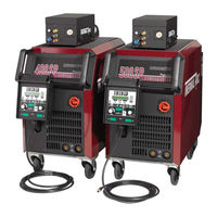
Thermal Arc POWERMASTER 500SP Service Manual (146 pages)
Brand:
Thermal Arc
| Category:
Welding System
| Size: 9 MB
Table of Contents
Service Manual
1
Table of Contents
4
Section 1
9
Safety Instructions and Warnings
9
Arc Welding Hazards
9
Principal Safety Standards
12
Symbol Chart
13
Precautions de Securite en Soudage a L'arc
14
Dangers Relatifs Au Soudage À L'arc
14
Principales Normes de Securite
17
Graphique de Symbole
18
Section 2
19
Introduction
19
How to Use this Manual
19
Equipment Identification
19
Receipt of Equipment
19
Machine Components (500SP, 400SP, and SP4000W)
20
Machine Components (400SP Compact Model)
21
Machine Components (320SP Compact Model)
22
Lifting Points
23
Power Supply Specifications (Part 1)
24
Power Supply Specifications (Part 2)
25
Wire Feeder Specifications
26
Features and Benefits Common to All Powermaster SP Systems
27
Section 3
29
Installation
29
Location
29
Transportation and Positioning
29
Fitting the Mains Cable into the Cable Gland
29
Voltage Change-Over
30
Connecting 3-Phase Input Power to 400SP or 500SP
31
Connecting Single-Phase Input Power to 320SP or 400SP or 500SP
33
Section
35
Quick Start Set up
35
Recommended Setup for MIG
35
TWECO PULSEMASTER PMA5512 500 AMP Weld Gun
39
Installing a New Wire Conduit
40
Section 4
41
Operation
41
General Safety Precautions
41
Welding Controls
42
Menu Structure
44
Main Menu
45
Special Functions
48
Smart GMAW, Pulse GMAW & Twinpulse Programs
49
Welding Setting Selection Guide
50
Section 5
53
Manual Gmaw Welding
53
Types of Weld Transfer Modes
53
Holding and Manipulating the Torch
54
Basics of Pulsed Arc Welding
56
Pulsed Arc Welding Parameters
57
Smart, Pulse or Twinpulse GMAW Welding
58
Conventional Manual GMAW/FCAW Welding
58
SMAW/STICK Welding
59
Section 6
61
Basic Service
61
Maintenance
61
System Troubleshooting Guide
62
Welding Process Troubleshooting Guide
63
Section 7
65
Advanced Service
65
Safety Precautions
65
Multivoltage Principle
66
Inverter Principle
67
Common Logic Functions
68
Gas Test
68
Pump Test
68
Reset Adjustments
68
Master Reset
68
Torque Setting(S)
68
Error Codes and Troubleshooting Guide
69
Overview of Mains Voltage Limits
69
Flowchart: Soft Power-Up Cycle at Switch on
70
Power-Up Schematic
71
Flowchart: Voltage Monitoring
72
Monitoring Bus Voltage
73
DP-MAPRO PC Board
74
MAPRO Connector Descriptions & Measuring Points
75
MV-MAPRO Diagram
79
DMR PC Board
80
DMR Connector Descriptions & Measuring Points
80
DMR Diagram
82
DMR Schematic
83
DS20BF PC Board
84
DS20BF Diagram
84
DS20BF Display Test
84
MVDRV / MVMDRV PC Board
85
MVMRV / MVMDRV Connector Descriptions & Measuring Points
87
MVDRV Schematic
88
MVMDRV Schematic
88
MVDRV Diagram
89
MVMDRV Diagram
90
MVPWRUP PC Board
91
MVPWRUP Connector Descriptions & Measuring Points
91
MVPWRUP Diagram
91
DK-GLCL PC Board
92
DK-GLCL PC Board Diagram
92
DP-UFI-BO PC Board
93
DP-UFI-BO PC Board Diagram
93
DP-EMV PC Board
94
DP-EMV Connector Descriptions & Measuring Points
94
DP-EMV PC Board Diagram
94
DS-VA PC Board
95
DS-VA Connector Descriptions & Measuring Points
95
DS-VA PC Board Diagram
95
DP-S3NEFI PC Board
95
Current Sensor VAC
96
Current Sensor VAC Connector Descriptions & Measuring Points
96
Current Sensor VAC Diagram
96
Control Transformer
97
Measuring Temperature
97
PCB Connection Diagram
98
Supply Voltages
99
Measuring Welding Current
100
Measuring the Flow Rate of the Cooling System
100
Measuring Output Voltage
101
Overcurrent Protection
101
Encoding Power Units
102
Parts List
103
Equipment Identification
103
How to Use this Parts List
103
Powermaster 320SP Exploded View Parts List (1 of 2)
104
Powermaster 320SP Exploded View Parts List (2 of 2)
106
Powermaster 400SP Compact Exploded View Parts List (1 of 2)
108
Powermaster 400SP Compact Exploded View Parts List (2 of 2)
110
Powermaster 400SP Remote, Water Exploded View Parts List
112
Powermaster 500SP Remote, Water Exploded View Parts List
114
Powermaster 400SP Power Module
116
Powermaster 500SP Power Module
117
Powermaster SP Water Cooling System
118
Powermaster SP HR911 Remote Pendant
119
Powermaster SP4000W Wire Feeder (Part 1 of 2)
120
Powermaster SP4000W Wire Feeder (Part 2 of 2)
122
Powermaster SP4000W Feed Plate Assembly
124
Appendix 1: Options and Accessories
127
Appendix 2: Feed Roll Information
128
Drive Roll Kits
128
Ordering Information
128
Appendix 3: Mounting the Torch Holder
129
Appendix 4: Sp-Series Block Diagram
130
Appendix 5: Powermaster 320P Power Schematic
132
Appendix 6: Powermaster 400Sp Power Schematic
134
Appendix 7: Powermaster 400Sp Compact Power Schematic
136
Appendix 8: Powermaster 500Sp Power Schematic
138
Appendix 9: Rectifier Diode Data Sheet
140
Appendix 10: Mosfet Data Sheet
141
Limited Warranty
142
Warranty Schedule
143
Global Customer Service Contact Information
145
Advertisement
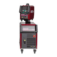
Thermal Arc POWERMASTER 500SP Service Manual (110 pages)
Powermaster Automation
Brand:
Thermal Arc
| Category:
Welding System
| Size: 7 MB
Table of Contents
Service Manual
1
Table of Contents
4
Safety Instructions and Warnings
7
Arc Welding Hazards
7
Principal Safety Standards
10
Symbol Chart
11
Precautions de Securite en Soudage a L'arc
12
Dangers Relatifs Au Soudage À L'arc
12
Principales Normes de Securite
15
Graphique de Symbole
16
Introduction
17
How to Use this Manual
17
Equipment Identification
17
Receipt of Equipment
17
Machine Components
18
Power Supply Specifications (Part 1)
19
Power Supply Specifications (Part 2)
20
Wire Feeder Specifications
21
Installation
23
Location
23
Voltage Changeover
23
Connecting 3-Phase Input Power to 400SP or 500SP
24
Connecting Single-Phase Input Power to 400SP or 500SP
26
Quick Start Set up
28
Recommended Setup for MIG
28
Pulsemaster PMA512S-3545 500 Amp Weld Gun (When Welding by Hand)
32
Installing a New Wire Conduit
33
Manual Operation
35
General Safety Precautions
35
Welding Controls
36
Menu Structure
38
Main Menu
39
Special Functions
42
Smart GMAW, Pulse GMAW & Twinpulse Programs
43
Welding Setting Selection Guide
44
Robotic Operation
47
Robot Interface INT06
47
Digital Inputs and Outputs
47
Analog Inputs
48
Robot Interface Schematic
49
Robot Interface INT06 PC Board Schematic
51
42-Pin Harting Socket
52
Configuration at Front Panel Menu
56
Robot Tool Software Installation
57
Decimal-Binary Conversion
58
Manual Gmaw Welding
59
Types of Weld Transfer Modes
59
Holding and Manipulating the Torch
60
Basics of Pulsed Arc Welding
62
Pulsed Arc Welding Parameters
63
Smart, Pulse or Twinpulse GMAW Welding
64
Conventional Manual GMAW/FCAW Welding
64
SMAW/STICK Welding
65
Basic Service
67
Maintenance
67
System Troubleshooting Guide
68
Welding Process Troubleshooting Guide
69
Error Codes
70
Advanced Service
71
Safety Precautions
71
Inverter Principle
72
Common Logic Functions
73
Gas Test
73
Pump Test
73
Reset Adjustments
73
Master Reset
73
Torque Setting(S)
73
Control Transformer
74
DP-MAPRO PC Board
75
DMR PC Board
76
DS20BF PC Board
76
DK-PWRUP04 PC Board
76
DP-S3NEFI PB Board
76
DK-DCDRV / DK-S3DRV PC Board
77
DK-GLCL PC Board
78
DP-UFI-BO PC Board
78
DP-EMV PC Board
78
LSW PC Board
78
DS-VA PC Board
78
DS-ERW PC Board
78
Section 9
79
Parts List
79
Equipment Identification
79
How to Use this Parts List
79
Powermaster 400SP & 500SP Robotic Exploded View Parts List (1 of 2)
80
Powermaster 400SP & 500SP Robotic Exploded View Parts List (2 of 2)
82
Powermaster 400SP Power Module
84
Powermaster 500SP Power Module
85
Powermaster SP Water Cooling System
86
Powermaster SP HR911 Remote Pendant
87
Powermaster SP 4000R Wire Feeder
88
Powermaster SP4000R Feed Plate Assembly
90
Appendix 1: Options and Accessories
93
Appendix 2: Feed Roll Information
94
Appendix 3: Mounting the Torch Holder
95
Appendix 4: Sp-Series Block Diagram
96
Appendix 5: Powermaster 400Sp Power Schematic
98
Appendix 6: Powermaster 500Sp Power Schematic
100
Appendix 7:Robotic Interface Diagram
102
Appendix 8: Rectifier Diode Data Sheet
103
Appendix 9: Hybrid Esbt Data Sheet
104
Limited Warranty
106
Warranty Schedule
107
Global Customer Service Contact Information
109
Thermal Arc POWERMASTER 500SP Operator's Manual (70 pages)
Brand:
Thermal Arc
| Category:
Welding System
| Size: 3 MB
Table of Contents
Operator Manual
1
Table of Contents
4
Safety Instructions and Warnings
7
Arc Welding Hazards
7
Principal Safety Standards
10
Symbol Chart
11
Precautions de Securite en Soudage a L'arc
12
Dangers Relatifs Au Soudage À L'arc
12
Principales Normes de Securite
15
Graphique de Symbole
16
Introduction
17
How to Use this Manual
17
Equipment Identification
17
Receipt of Equipment
17
Machine Components (500SP, 400SP, and SP4000W)
18
Machine Components (400SP Compact Model)
19
Machine Components (320SP Compact Model)
20
Lifting Points
21
Power Supply Specifications (Part 1)
22
Power Supply Specifications (Part 2)
23
Wire Feeder Specifications
24
Features and Benefits Common to All Powermaster SP Systems
25
Features and Benefits Common to All Powermaster SP Systems (Con't)
26
Installation
27
Location
27
Transportation and Positioning
27
Fitting the Mains Cable into the Cable Gland
27
Voltage Change-Over
28
Connecting 3-Phase Input Power to 400SP or 500SP
29
Connecting Single-Phase Input Power to 320SP or 400SP or 500SP
31
Quick Start Set up
33
Recommended Setup for MIG
33
TWECO PULSEMASTER PMA5512 500 AMP Weld Gun
37
Installing a New Wire Conduit
38
Operation
39
General Safety Precautions
39
Welding Controls
40
Menu Structure
42
Main Menu
43
Special Functions
46
Smart GMAW, Pulse GMAW & Twinpulse Programs
47
Welding Setting Selection Guide
48
Section 5
51
Manual Gmaw Welding
51
Types of Weld Transfer Modes
51
Holding and Manipulating the Torch
52
Basics of Pulsed Arc Welding
54
Pulsed Arc Welding Parameters
55
Smart, Pulse or Twinpulse GMAW Welding
56
Conventional Manual GMAW/FCAW Welding
56
SMAW/STICK Welding
57
Section 6
59
Service
59
Maintenance
59
System Troubleshooting Guide
60
Welding Process Troubleshooting Guide
61
Error Codes
62
Appendix 1: Optional Accessories and Consumables
63
Appendix 2: Feed Roll Information
64
Appendix 3: Mounting the Torch Holder
65
Limited Warranty
66
Warranty Schedule
67
Global Customer Service Contact Information
69
Advertisement
Thermal Arc POWERMASTER 500SP Service Manual (40 pages)
Brand:
Thermal Arc
| Category:
Welding System
| Size: 2 MB
Table of Contents
Table of Contents
2
Safety Precautions
3
Common Logic Functions
4
Inverter Principle
5
Troubleshooting Guide
6
Pc-Board DP-MAPRO
7
Pc-Board DMR
10
Pc-Board DS20BF
12
Pc-Board DK-DCDRV / DK-S3DRV
14
Pc-Board PWRUP04
19
Pc-Board DP-S3NEFI
20
Pc-Board DP-UFI-BO
22
Pc-Board DP-EMV
22
Pc-Board LSW
23
Current Sensor VAC
23
Pc-Board DS-VA
24
Pc-Board PP-90R
24
Control Transformer
25
Temperature Monitoring
26
Supply Voltages
27
Monitoring Welding Current
28
Cooling Unit
29
Welding Voltage Monitoring
30
Control and Monitoring Wire Feed Motor
31
Remote Control Interface
32
Monitoring Primary Current
33
Power-Up Cycle
34
Monitoring Bus Voltage
35
Identifi Cation Power Units
36
Testing Mosfets
37
Inside Diagram Diodes
38
Advertisement
Related Products
Thermal Arc 500
Thermal Arc 500P
Thermal Arc POWERMASTER 400SP
Thermal Arc POWERMASTER 320SP
Thermal Arc POWERMASTER 350P
Thermal Arc PowerMaster 350
Thermal Arc Fabricator 500S III
Thermal Arc PowerMaster 250
Thermal Arc 000 Pro K
Thermal Arc 155 SE
Thermal Arc Categories
Welding System
Inverter
Power Supply
More Thermal Arc Manuals
Login
Sign In
OR
Sign in with Facebook
Sign in with Google
Upload manual
Upload from disk
Upload from URL