Table of Contents
Advertisement
Quick Links
Advertisement
Table of Contents

Related Manuals for Guntamatic BIOSTAR FLEX


Summary of Contents for Guntamatic BIOSTAR FLEX
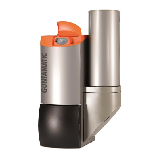
- Page 1 Pellet Boiler BIOSTAR FLEX/BOX/W Installation Instructions BS-A-00-00-00-01-IADE DE-B31-003-V07-0511 (Taurus) UK Distributor Treco Ltd Pyramid House Tiverton Business Park Tiverton, Devon EX16 6TG www.treco.co.uk info@treco.co.uk 0845 130 9012/ 01884 250 970...
- Page 2 We are always looking to improve our products and documentation. Any ideas and suggestions you may have will be gratefully received. GUNTAMATIC Heiztechnik GmbH a Georg Fischer Group Company Bruck 7 A-4722 PEUERBACH Tel: 0043 (0) 7276 / 2441-0 Fax: 0043 (0) 7276 / 3031 E-mail: info@guntamatic.com...
-
Page 3: Table Of Contents
Wiring requirements Electrical connections Final checks/Commissioning ......27 Standards/Regulations ........28 Plumbing diagrams........29-34 Electrical wiring diagram ........35 Control panel Wall controller set MK261 Boiler circuit board Technical data ............ 40 BIOSTAR FLEX/W 40-41 FLEX outfeed system BOX outfeed system... -
Page 4: Introduction
GUNTAMATIC provides no guarantee of any kind for any type of site work. Without making any claims as to completeness or... -
Page 5: Fire Safety (Minimum Fire Safety Requirements)
Caution: Compliance with the GUNTAMATIC minimum fire safety requirements is subject only to verification by the operator. The operator alone is responsible for strict compliance. Verification during commissioning is not provided for. - Page 6 BIOSTAR Installation instructions Minimum fire safety requirements BS-01-04-01-01-01-IADE BS-01-04-01-02-01-IADE Boiler room Floor of concrete construction, either bare or tiled. All materials for floor, walls and ceiling must be fire-resistant to F60 rating. If a fabric hopper is installed in the boiler room (not allowed in all countries), the floor walls and ceiling must be F90-rated.
-
Page 7: Boiler Room Requirements
The boiler room, pipes carrying water and any district heating pipes must be protected against freezing. BS-01-04-02-05-01-IADE Minimum room size Biostar FLEX at least 148 x 193 cm (W x L) Biostar W at least 194 x 193 cm (W x L) -
Page 8: Flue Requirements
BIOSTAR Installation instructions 1.4.3 Flue requirements BS-01-04-03-00-01-IADE The flue must be matched to the system in order to ensure economical and trouble-free operation. BS-01-04-03-01-01-IADE Important Use heat-insulated fireclay flues that are insensitive to damp. The flue gas temperature can be less than 105°C. -
Page 9: Fuel Store Requirements
BIOSTAR Installation instructions 1.4.4 Fuel store requirements BS-01-04-04-00-01-IADE BS-01-04-04-01-01-IADE Access doors/hatches Above-ground fuel stores must be provided with a door or hatch that opens outwards. So that the fuel cannot run out if the fuel store is opened by mistake, the inside of the access door/hatch opening must be covered with boarding (which must be removable from the outside). - Page 10 BIOSTAR Installation instructions BS-01-04-04-07-01-IADE Wall penetration If there is an auger conveyor passing through the storeroom wall, the gap in the wall must be filled with mineral wool and sealed by means of the non-contact (sound insulation) finishing plates provided. BS-01-04-04-08-01-IADE Filling the fuel store When pressure-filling the fuel store from a tanker truck, the air...
-
Page 11: Installation And Assembly
Carrying in dismantled The boiler body can be dismantled into parts for carrying in. If that is done, a person authorised by GUNTAMATIC must be consulted. Positioning and aligning the boiler... -
Page 12: Plumbing Connections
BIOSTAR Installation instructions Plumbing connections BS-02-04-00-00-01-IADE Biostar 12/15/23 - FLEX/W F → Heating return, 1" B → Heating flow, 1" C → Boiler sensor/STL D → External thermostat, ½" (if required) E → Safety valve BS-02-04-00-01-01-IADE Temperature-relief heat exchanger Connection of a temperature-relief valve is not required according to the standards ÖNORM B 8131 and DIN 4751. - Page 13 BIOSTAR Installation instructions Connection with low-temperature systems (mixer valves only): With low-temperature systems (underfloor or warm-air systems only) that are operated exclusively using mixer valves and low flow temperatures, it is necessary to fit a bypass pump between the flow and return pipes (see plumbing diagram in the Appendix).
-
Page 14: Filling And Bleeding The System
°dH > 8.4 > 500kW: if °dH > 0.11 Water heater If a water heater is also used in addition to the GUNTAMATIC boiler, it should be filled according to the installation instructions for it. Filling the system ... -
Page 15: Connecting The Flue
BIOSTAR Installation instructions Connecting the flue BS-02-06-00-00-01-IADE BS-02-06-00-01-01-IADE The boiler is connected to the flue by means of a flue connecting pipe which must be gas-tight and insulated between the heating boiler and the chimney (insulation thickness 50 mm). Flue connecting pipe The following diameters should be used: ... -
Page 16: Energy Saving Draught Regulator And Pressure-Surge Compensator
BIOSTAR Installation instructions Energy-saving flue draught regulator and pressure-surge compensator BS-02-07-00-00-01-IADE Fitting an energy-saving flue draught regulator/pressure-surge compensator (Class RE) is absolutely imperative. Purpose To ventilate the flue when the system is not in operation To compensate for pressure surges ... -
Page 17: Fuel Outfeed Installation
BIOSTAR Installation instructions Fuel outfeed installation BS-02-08-00-00-01-IADE 2.8.1 FLEX system BS-02-08-01-00-01-IADE Important → Ensure the inlet opening is on the correct side. A → Conveying direction B → Inlet opening always this side C → Direction of rotation D → Scraper E →... - Page 18 BIOSTAR Installation instructions Fill the gap (6) in the wall around the conveyor with mineral wool. Cover the hole on both sides of the wall with the masking plates supplied (7), fitting them so that they do not touch the conveyor. FLEX fuel outfeed system Fig.
- Page 19 BIOSTAR Installation instructions Fitting the boarding in the FLEX system storeroom (Fig. 10) A → Batten B → Board trimmed by 3 cm C → Supporting batten (10 x 10) D → Wooden boards, planed, or blockboard (3 cm) E → Square batten, 10 x 10 F →...
- Page 20 BIOSTAR Installation instructions Filler set The pellet store requires at least 2 filler pipes (for pressure- filling and air extraction). Whenever possible, the filler pipes should be placed centrally in the shorter side of the storeroom. Minimum distance from ceiling and walls 25 cm. ...
-
Page 21: Box System
BIOSTAR Installation instructions 2.8.2 BOX system BS-02-08-02-00-01-IADE The BOX fabric hopper system is installed as described in the separate installation instructions. They are supplied with the BOX system. 2.8.3 Boiler-mounted hopper system BS-02-08-03-00-01-IADE The base surface and immediate area of the boiler must only be constructed of fire-resistant materials. - Page 22 BIOSTAR Installation instructions Sprinkler system In Austria the system may legally be operated without a sprinkler system. Connection of a sprinkler system is at the discretion of the operator or else is subject to the locally applicable regulations. The fire extinguishing system cannot be installed until the boiler and boiler-mounted hopper positions have been adjusted.
-
Page 23: Electrical Connections
BIOSTAR Installation instructions Electrical connections BS-03-00-00-00-01-IADE Heating system electrical connections BS-03-01-00-00-01-IADE Mains connection 230V, 50Hz, 13A fuse (surge protector recommended) Standard specifications 1 Boiler control panel (BCE) 1 Boiler circuit board (230V AC) 1 Safety temperature limiter (STL) ... -
Page 24: Wiring Requirements
BIOSTAR Installation instructions Wiring requirements BS-03-02-00-00-01-IADE Surge protection Where CAN bus cables run between different buildings, the earthing conductors of the buildings must be connected to each other for potential equalisation purposes. If the earthing conductors cannot be interconnected, a 10 mm rustless ring earth must be laid along with the CAN bus cable in the ground. -
Page 25: Electrical Connections
BIOSTAR Installation instructions Electrical connections BS-03-03-00-00-01-IADE The electrical connections to the boiler system on site may only be made by an approved electrical installer observing all the applicable regulations. In addition, it is essential that electrical system components are protected against damage from heat radiation. - Page 26 BIOSTAR Installation instructions BS-03-03-00-03-01-IADE Outside-temperature based controller The MKR outside-temperature based heating circuit controller set is offered as an option and activated on the boiler circuit board if required. The MK261 wall controller set, on the other hand, can only be fitted externally and connected to the system via the CAN bus.
-
Page 27: Final Checks/Commissioning
Always leave the boiler room clean. Initial commissioning Commissioning must only be carried out by GUNTAMATIC or a qualified specialist. The precondition is that the flue technician, heating installer and electrician have cleared the system for operation. The authorised GUNTAMATIC specialist will carry out the following work during commissioning: ... -
Page 28: Standards/Regulations
BIOSTAR Installation instructions Standards/Regulations BS-05-00-00-00-01-IADE The boiler is designed as a Class 3 appliance as defined by the draft standard ÖNORM EN 303-5 (CEN/TC7/WG 1 – Doc. N 36-D) of 15/12/1996 and the agreement of the [Austrian] Federal States according to Art. 15a BVG, in accordance with the Austrian fire safety regulations, safety systems, CE and on safety measures for small combustion heating systems and the combustion heating system approval regulations (LGB.33/1992) of the Austrian Federal State of Steiermark. -
Page 29: Plumbing Diagrams
BIOSTAR Installation instructions Plumbing diagrams BS-06-00-00-00-01-IADE Diagram no.: BS-01-1 BS with modulating control radiator system outside-temperature based controller, ECO305 DHW cylinder Diagram no.: BS-02-1 BS with pure low-temperature system outside-temperature based controller, ECO305 DHW cylinder Diagram no.: BC-03-2 BS with PSF thermal store inc. water supply unit outside-temperature based controller, PSF thermal store Diagram no.: BS-04-1 BS Duo with KOBRA solid-fuel boiler... - Page 30 Outside-temperature based controller, ECO305 DHW cylinder Caution: For modulating control mode, one heating circuit must be in the form of a radiator heating circuit. www.guntamatic.com Diagram no. BS-01-1 GUNTAMATIC components Electrical connections as per operating and installation instructions 1. BIOSTAR boiler As price list 2.
- Page 31 Outside-temperature based controller, ECO305 DHW cylinder www.guntamatic.com Diagram no. BS-02-1 Electrical connections as per operating and installation instructions GUNTAMATIC components 1. BIOSTAR boiler As price list 2. Flue draught regulator RE (size to suit flue diameter) As price list 3.
- Page 32 Outside-temperature based controller, thermal store PSF inc. water supply unit www.guntamatic.com Diagram no. BS-03-2 Electrical connections as per operating and installation instructions GUNTAMATIC components 1. BIOSTAR boiler As price list 2. Flue draught regulator RE (size to suit flue diameter) As price list 3.
- Page 33 Diagram no. BS-04-1 Electrical connections as per operating and installation instructions GUNTAMATIC components 1. BIOSTAR DUO boiler with KOBRA solid-fuel boiler Flue gas thermostat supplied opens the enabling switch (terminals 22/23) at above 88°C 2. Outside temp. based controller set MKR Art.
- Page 34 Outside-temperature based controller, thermal store PSF inc. water supply unit www.guntamatic.com Diagram no. BSM-06-1 Electrical connections as per operating and installation instructions GUNTAMATIC components 1. BIOSTAR boiler combined with BIOSMART wood-burning boiler 2. Flue draught regulator RE (size to suit flue diameter) As price list ...
-
Page 35: Electrical Wiring Diagram
BIOSTAR Installation instructions Electrical wiring diagram BS-07-00-00-00-01-IADE Control panel (use only flexible cables for wiring) BS-07-01-00-00-01-IADE = Display and control unit (touch screen) Service = Connection socket SY-BUS = Connection socket/cable connection betw. BCE and boiler PCB Ethern. = Connection socket (inactive) SD-Card = Slot for SD memory card = Connection socket for CAN bus... -
Page 36: Wall Controller Set Mk261
BIOSTAR Installation instructions Wall controller set MK261 (use only flexible cables for wiring) BS-07-02-00-00-01-IADE Connector: H1/H2 – H3/H4 – H5/H6 RG 0-8 = Analogue room stat input for HC 0 - 8 = Connect only if not connected on boiler PCB Connector: H7/H8 Connector: H9/H10 –... -
Page 37: Boiler Circuit Board
BIOSTAR Installation instructions Boiler circuit board (use only flexible cables for wiring) BS-07-03-00-00-01-IADE RG 0 (1, 2) = Analogue room stat input for HC 0 (1, 2) Connector: H1/H2 (H3/H4, H5/H6) = Outside sensor input Connector: H7/H8 VF 2 (1) = Flow temperature sensor input for heating circuit 2 (1) Connector: H9/H10 (H11/H12) SF 0... - Page 38 BIOSTAR Installation instructions Notes BS-D-00-00-00-01-IADE...
- Page 39 BIOSTAR Installation instructions Notes BS-D-00-00-00-01-IADE...
-
Page 40: Technical Data
BIOSTAR Installation instructions Technical data BS-08-00-00-00-01-IADE BIOSTAR FLEX BS-08-01-00-00-01-IADE BIOSTAR 12 BIOSTAR 15 BIOSTAR 23 Type FLEX FLEX FLEX Fuel Pellets, 6mm Pellets, 6mm Pellets, 6mm ÖNORM M7135 Boiler output Pellets, 3.3 - 12 kW Pellets, 3.5 - 15 kW Pellets, 6.9 - 23 kW... - Page 41 BIOSTAR Installation instructions BIOSTAR W BIOSTAR 12 BIOSTAR 15 BIOSTAR 23 Type Fuel Pellets, 6mm Pellets, 6mm Pellets, 6mm ÖNORM M7135 Boiler output Pellets, 3.3 - 12 kW Pellets, 3.5 - 15 kW Pellets, 6.7 - 20 kW ÖNORM M7135 Required flue draught 0.10 0.10...
-
Page 42: Flex Outfeed System
BIOSTAR Installation instructions FLEX system outfeed BS-08-02-00-00-01-IADE Wall opening for auger: Width 330 mm Height 250 mm Dimension A > Dimension B > Storeroom Auger length internal clear length 1080 mm – 1559 mm FLEX 1.0 m 1560 mm – 2039 mm FLEX 1.5 m 2040 mm –... -
Page 43: Box Outfeed System
BIOSTAR Installation instructions BOX system outfeed BS-08-03-00-00-01-IADE Dimension A - B Dimension C (variable) Hopper capacity in m³ Hopper capacity in BOX 5.2 170 cm x 170 cm 180 cm - 250 cm 3.0 m³ to 5.2m³ 2.0 t to 3.4 t BOX 7.5 210 cm x 210 cm 180 cm - 250 cm... - Page 44 Treco Ltd Pyramid House Tiverton Business Park Tiverton, Devon EX16 6TG www.treco.co.uk info@treco.co.uk 0845 130 9012 or 01884 250790 GUNTAMATIC Heiztechnik GmbH A – 4722 PEUERBACH Bruck 7 Tel: 0043 (0) 7276 / 2441-0 Fax: 0043 (0)7276 / 3031 E-mail: info@guntamatic.com...
Need help?
Do you have a question about the BIOSTAR FLEX and is the answer not in the manual?
Questions and answers