Table of Contents
Advertisement
WARRANTY
Top Flite Models guarantees this kit to be free from defects in both material and workmanship at the date of
purchase. This warranty does not cover any component parts damaged by use or modification. In no case
shall Top Flite's liability exceed the original cost of the purchased kit. Further, Top Flite reserves the
right to change or modify this warranty without notice.
In that Top Flite has no control over the final assembly or material used for final assembly, no liability shall be
assumed nor accepted for any damage resulting from the use by the user of the final user-assembled prod-
uct. By the act of using the user-assembled product, the user accepts all resulting liability.
If the buyer is not prepared to accept the liability associated with the use of this product, the buyer is
advised to return this kit immediately in new and unused condition to the place of purchase.
To make a warranty claim send the
defective part or item to Hobby
Services at this address:
Include a letter stating your name, return shipping address, as much contact information as possible (daytime
telephone number, fax number, e-mail address), a detailed description of the problem and a photocopy of the
purchase receipt. Upon receipt of the package the problem will be evaluated as quickly as possible.
READ THROUGH THIS MANUAL BEFORE STARTING CONSTRUCTION. IT CONTAINS IMPORTANT INSTRUCTIONS AND WARNINGS CONCERNING THE ASSEMBLY AND USE OF THIS MODEL.
© 2015 Top Flite, a Hobbico
®
company.
Hobby Services
3002 N. Apollo Dr. Suite 1
Champaign IL 61822 USA
INSTRUCTION MANUAL
Top Flite Models Champaign, IL
Telephone (217) 398-8970, Ext. 5
airsupport@top-flite.com
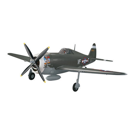
SPECIFICATIONS
Wingspan:
85 in [ 2160 mm]
Wing Area:
1329 sq in [85.7 dm
Weight:
19.5 – 21.5 lb [8842 – 9749 g]
Wing
34 – 37 oz/sq ft
2
Loading:
[104 –113 g/dm
]
Length:
75 in [1905 mm]
Radio:
5-8 channel
2.6 – 4.0 cu in
Engine:
[43 – 65 cc] spark ignition gas
Elec. Motor:
RimFire 65 cc 80-85-160kV
Flight
12S 5000 mAh
Battery:
2
]
TOPA0714
Advertisement
Table of Contents

Related Manuals for Top Flite P-47 Razorback


Summary of Contents for Top Flite P-47 Razorback
-
Page 1: Instruction Manual
Weight: 19.5 – 21.5 lb [8842 – 9749 g] In that Top Flite has no control over the final assembly or material used for final assembly, no liability shall be Wing 34 – 37 oz/sq ft... -
Page 2: Table Of Contents
ELECTRIC MOTOR INSTALLATION ..21 – especially for a warbird! The Top Flite Giant P-47 (with DECISIONS YOU MUST MAKE ....3 INSTALL THE AIR RETRACT CONTROLS . -
Page 3: Safety Precautions
The radio equipment and number of channels required the photos. In those instances the written instructions to fl y the Top Flite Giant P-47 Razorback ARF depends REMEMBER: Take your time and follow the instructions should be considered as correct. -
Page 4: S.bus System
The Giant P-47 Razorback ARF requires a servo to separate channels of the receiver and mixed together. Qty. Items Required operate the air control valve if using pneumatic retracts, The two fl ap servos and the two elevator servos also 6"... -
Page 5: How Do You Install
S. Bus servos and receivers are HV or High Voltage, meaning that you could run RETRACTABLE LANDING GEAR a straight 2S LiPo for your receiver battery. The Top Flite Giant P-47 Razorback ARF may be assembled with either the Robart pneumatic or electric... -
Page 6: Additional Items Required
Here is a list of optional tools mentioned in the manual ❍ Propeller and spare propellers suitable for your thrust angles have been factory-built into this model. that will help you build the Giant P-47 Razorback ARF. engine or motor. However, some technically-minded modelers may wish ❍... -
Page 7: Ordering Replacement Parts
ORDERING REPLACEMENT PARTS Replacement parts for the Top Flite Giant P-47 Razorback ARF are available using the order numbers in the Replacement Parts List that follows. The fastest, most economical service can be provided by your hobby dealer or mail-order company. Not all... -
Page 8: Assemble The Wings
ASSEMBLE THE WINGS HINGE THE AILERONS Start with the left wing so the assembly matches the photos the fi rst time through. The P-47 had many attributes that led to its ❏ 1. Pull on the ailerons and elevators, making sure reputation. -
Page 9: Mount The Retracts
metal screws to secure the servo mounting blocks to MOUNT THE RETRACTS the aileron servo hatch. Use thin CA to harden the Install the left retract fi rst. screw threads. ❏ ❏ 1. Use a hex wrench to loosen the strut mounting bolt and remove the strut. - Page 10 ❏ ❏ 13. Install a #4 fl at washer on 4-40 x 3/8" [9.5mm] ❏ ❏ ❏ ❏ 9. Set the retract cover over the retract and drill 6. Hold the retract in the wing. Using the mounting machine screw. Insert the machine screw through a 1/16"...
-
Page 11: Install The Flap Servos
INSTALL THE FLAP SERVOS the aileron servo arm 5/8" [15.9mm] from the center of the arm. HOW TO SOLDER 1. Use denatured alcohol or other solvent to thoroughly clean the pushrod. Roughen the end of the pushrod with coarse sandpaper where it is to be soldered. -
Page 12: Join The Wing
The Thunderbolt was a massive airplane, the biggest and heaviest single engine, single-place fi ghter ever built. The engine, the Pratt & Whitney 18 cylinder twin-row radial, developed 2,000 HP and was the most powerful engine at the time. However, in turn, it needed a highly effi cient duct system for its super-charger. -
Page 13: Assemble The Fuselage
together with rubberbands around the wing dowels Clean the tubes with denatured alcohol and insert and the trailing edge. both tubes back into the fuselage until the end exits on the opposite side by approximately 1" [25.4mm]. ❏ 5. Remove the rubberbands and separate the wing halves. -
Page 14: Mount The Retractable Tail Gear
is too much resistance, or if you are not able to move hinge into the fi n and wipe away any excess epoxy the rudder left and right 2" [50.8mm], widen the gap that squeezes out of the hole. slightly between the rudder and the fi n. ❏... - Page 15 ❏ 4. Enlarge the middle hole in both sides of the steering arm with a 3/32" [2.4mm] drill. Insert a 2-56 ❏ ball link ball in the hole. Secure each ball with a 2-56 8. Now pull on the long end of the cable to reduce nut and a drop of threadlocker.
-
Page 16: Install The Elevator & Rudder Servos
INSTALL THE ELEVATOR & RUDDER SERVOS ❏ 3. Mount the control horns to the elevators and the rudder. Follow the same procedure used for the ❏ ailerons, by drilling 3/32" [2.4mm] holes and using #4 x 5. Install solder clevises on the elevator servo arms ❏... -
Page 17: Gas Engine Installation
GAS ENGINE INSTALLATION ❏ 2. Drill a 13/64" (5 mm) hole through the fi rewall If you are powering the P-47 Razorback with an at each of the appropriate locations marked with an ❏ 9. Cut in half one of the 12" (305 mm) long hook electric motor, skip ahead to ELECTRIC MOTOR “X”... - Page 18 it as shown. Apply thread locker to the screw before reinstalling it. ❏ 5. Temporarily install the engine inverted on the aluminum standoffs. ❏ 9. Glue the forward fuel tank support to the fi rewall, aligning the embossed arrows. The edge of the tank support should align with the two slots.
- Page 19 ❏ ❏ ❏ 15. Position the throttle stick so that it is centered 11. Mount the throttle servo in the servo tray and 13. Glue the plywood pushrod support so that the on the transmitter. Adjust the throttle servo arm so slide a plywood pushrod support onto the outer pushrod is inline with the servo arm and on the outside that it is centered on the throttle servo.
-
Page 20: Assemble & Install The Fuel Tank
excess wire can be secured with a piece of rubber band (not included) glued to the fi rewall box. ❏ 20. Wrap the ignition battery in R/C foam rubber and attach it to the bottom of the fi rewall box with hook and loop material. -
Page 21: Electric Motor Installation
ELECTRIC MOTOR INSTALLATION ❏ 3. Glue the aft battery tray support to the battery tray and the fuselage sides. ❏ 1. The removable battery hatch is secured at the factory with four #2 x 3/8" (9.5 mm) sheet metal screws. Remove the four screws from the inside of the fuselage. - Page 22 ❏ 6. Follow the Stand Off Motor Mount instructions to install the motor on the fi rewall box. The RimFire 65 motor uses the embossed ‘X’ pattern on the front of the fi rewall box. Drill a 5/16" [8mm] hole at each mark. ❏...
-
Page 23: Install The Air Retract Controls
a 1/16" (1.6 mm) pilot hole in the servo tray using the four mounting holes in the retract servo tray as guides. Attach the retract servo tray with #2 x 3/8" (9.5 mm) sheet metal screws and #2 fl at washers. ❏... -
Page 24: Install The Cowl
INSTALL THE TAIL GEAR COVER Drill a 1/16" [1.6mm] hole through the forward former using the hole in the cowl mounting bracket as a guide. ❏ 1. Operate the tail gear retract a couple of times, Attach the cowl mounting bracket to the forward former making any adjustments as needed. - Page 25 ❏ 6. The plywood engine frame can be painted black. ❏ 10. Drill 1/8" (3.2 mm) holes in the bottom of the ❏ Use 6-minute epoxy to glue the plastic radial engine 12. The plywood engine frame can be painted black. rocker arms and in the crankcase as shown.
-
Page 26: Apply The Final Details
❏ in the cowl. It should fi t over the rocker arm covers 19. Route the vent fuel line from the fuel tank out of the radial engine, against the inner lip of the cowl. the exhaust exit in the bottom of the cowl. Once satisfi... - Page 27 ❏ ❏ ❏ 6. Trim the sides of the cockpit leaving approximately 3. Glue the two oil cooler louvers to the forward 5. Insert one of the red round headed pins in the 1/16" [1.6mm] lip around the edges. Apply the decals lower fuselage following the same procedure used to lower right corner of the instrument panel to represent to the numbered locations on the side cockpit panels.
-
Page 28: Finish The Wing
FINISH THE WING ❏ 5. Glue the belly pan to the wing using 30-minute ❏ epoxy. Make sure that the belly pan is tight against 8. Now is the time to securely install a pilot before the bottom of the wing and centered between the gluing the canopy on. -
Page 29: Apply The Decals
6-minute epoxy. Note the distance from the leading edge of the wing to the end of each gun barrel. The “belly pan” under the wing conceals the air ducting for the supercharger. One duct carries air from the intake in the front of the cowl back ❏... -
Page 30: Get The Model Ready To Fly
We use a Top Flite Precision Magnetic Prop Balancer (TOPQ5700) in the workshop and keep a Great Planes Fingertip Prop Balancer (GPMQ5000) in our fl ight box. -
Page 31: Balance The Model Laterally
1. Turn on the transmitter and receiver and center Giant P-47 Razorback ARF fl ies, you would like to the trims. If necessary, remove the servo arms from change the throws to suit your taste, that is fi ne. -
Page 32: Balance The Model (C.g.)
ruler forward so it will remain contacting the trailing If your radio does not have dual rates, we recommend BALANCE THE MODEL (C.G.) edge. The distance the elevator moves up from center setting the throws at the high rate settings. More than any other factor, the C.G. -
Page 33: Check List
❏ weight required, it can be permanently attached. If 6. Use threadlocking compound to secure critical This is where your model should balance for the fi rst required, tail weight may be added by cutting open fasteners such as the set screws that hold the wheel fl... -
Page 34: Preflight
GROUND CHECK AND RANGE CHECK Make all engine adjustments from behind the rotating propeller. Run the engine for a few minutes to make sure it idles The engine or motor gets hot! Do not touch it during or right reliably, transitions smoothly and maintains full power after operation. -
Page 35: Ama Safety Code (Excerpts)
Insecure servo mounting; and one of air shows, or model fl ying demonstrations until it has Since the Giant P-47 Razorback ARF qualifi es as a the most prevalent causes of fl utter; Flying an over- been proven to be airworthy by having been previously, “giant scale’... -
Page 36: Flight
Take it easy with the Giant P-47 Razorback ARF for the maintain your glide path and airspeed. If you are going to fi rst few fl ights, gradually getting acquainted with it as you overshoot, smoothly advance the throttle (always ready gain confi... - Page 37 O.S. GT60 MOUNTING HOLES I.D. TAG GEAR DOOR DRILL GUIDE...
- Page 38 See templates on reverse side.
- Page 39 NOTES:...
Need help?
Do you have a question about the P-47 Razorback and is the answer not in the manual?
Questions and answers