Advertisement
Table of Contents
- 1 Table of Contents
- 2 Safety Information
- 3 Package Contents
- 4 Hardware Contents
- 5 Preparation
- 6 Initial Installation
- 7 Wiring
- 8 Final Installation
- 9 Installing Fan Without Included Light Kit (Optional)
- 10 Operating Instructions
- 11 Care and Maintenance
- 12 Troubleshooting
- 13 Warranty
- 14 Replacement Parts List
- Download this manual
See also:
Installation Manual
Harbor Breeze® is a registered trademark
of LF, LLC. All Rights Reserved.
ATTACH YOUR RECEIPT HERE
Serial Number
Questions, problems, missing parts? Before returning to your retailer, call our customer
service department at
5 p.m., EST, Friday.
XXXXXX
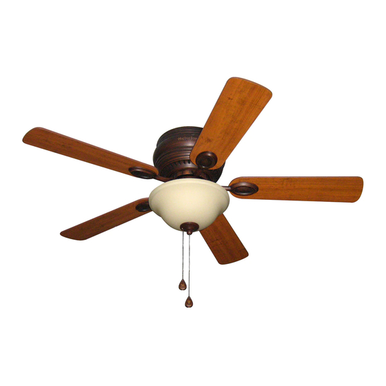
MAYFIELD CEILING FAN
Purchase Date
1-800-643-0067, 8 a.m. - 6 p.m., EST, Monday - Thursday, 8 a.m. -
Lowes.com/harborbreeze
1
ITEM
#0331094
0331096
MODEL
#BTH44ABZC5C
BTH44BNK5C
Español p. 20
LISTED
E124404
Advertisement
Table of Contents

Subscribe to Our Youtube Channel
Related Manuals for Harbor Breeze BTH44ABZC5C


Summary of Contents for Harbor Breeze BTH44ABZC5C
- Page 1 ITEM #0331094 0331096 MAYFIELD CEILING FAN MODEL #BTH44ABZC5C BTH44BNK5C Harbor Breeze® is a registered trademark Español p. 20 of LF, LLC. All Rights Reserved. LISTED ATTACH YOUR RECEIPT HERE E124404 Serial Number Purchase Date Questions, problems, missing parts? Before returning to your retailer, call our customer service department at 1-800-643-0067, 8 a.m.
-
Page 2: Table Of Contents
TABLE OF CONTENTS Safety Information .......................2 Package Contents .......................4 Hardware Contents ..........................5 Preparation ..........................5 Initial Installation ........................6 Wiring ..........................8 Final Installation ........................10 Installing Fan Without Included Light Kit (Optional) ............14 Operating Instructions .......................15 Care and Maintenance ......................16 Troubleshooting .........................17 Warranty ..........................18 Replacement Parts List .....................19 SAFETY INFORMATION READ AND SAVE THESE INSTRUCTIONS... - Page 3 SAFETY INFORMATION WARNINGS To reduce the risk of fire, electrical shock, or personal injury, mount fan to outlet box marked "ACCEPTABLE FOR FAN SUPPORT OF 35 LBS. (15.9 KG) OR LESS" and use mounting screws provided with the outlet box. Most outlet boxes commonly used for the support of lighting fixtures are not acceptable for fan support and may need to be replaced.
-
Page 4: Package Contents
PACKAGE CONTENTS PART DESCRIPTION PART DESCRIPTION QUANTITY QUANTITY Motor Screw Mounting Bracket (preassembled) + 1 extra Motor Housing 5.4 mm Lock Washer Motor Assembly (preassembled) + 1 extra Light Kit Fitter Hex Nut (preassembled) Glass Shade Lock Washer Pull Chain Extension (preassembled) Blade Mounting Bracket Screw... -
Page 5: Hardware Contents
HARDWARE CONTENTS (shown actual size) Blade Fiber Screw Blade E3 Wire Washer Connector Qty. 15 + 1 extra Qty. 15 Qty. 4 + 1 extra PREPARATION Before beginning assembly of product, make sure all parts are present. Compare parts with package contents list and hardware contents list. -
Page 6: Initial Installation
INITIAL INSTALLATION Turn off circuit breakers and wall switch to the fan supply line leads. DANGER: Failure to disconnect power supply prior to installation may result in serious injury or death. Check to make sure blades (G) are at least 30 in. from any obstruction and at least 7 ft. - Page 7 INITIAL INSTALLATION Remove motor screws (N) and 5.4 mm lock washers (O) from underside of motor and save for blade arm (J) attachment later on. [If there are plastic motor blocks installed with the motor screws (N) and 5.4 mm lock washers (O), discard the plastic motor blocks.] Motor Install ball end of motor assembly (C) into...
-
Page 8: Wiring
WIRING WARNING: To reduce the risk of fire, electrical shock, or personal injury, wire connectors provided with this fan are designed to accept only one 12-gauge house wire and two lead wires from the fan. If your house wire is larger than 12-gauge or there is more than one house wire to connect to the corresponding fan lead wires, consult an electrician for the proper size wire connectors to use. - Page 9 WIRING 1C. FAN AND LIGHT CONTROLLED BY TWO FAN AND LIGHT CONTROLLED BY TWO WALL SWITCHES WALL SWITCHES: If you intend to control the fan and light with separate wall switches, connect BLACK (WALL SWITCH) BLACK wire from fan to BLACK wire from the (WALL SWITCH FOR LIGHT) 120 V Power independent wall switch for the fan.
-
Page 10: Final Installation
WIRING IMPORTANT: Using a full range dimmer switch (not included) to control fan speed will cause a loud humming noise from fan. To reduce the risk of fire or electrical shock, do NOT use a full range dimmer switch to control fan speed. - Page 11 FINAL INSTALLATION Locate motor screws (N) and lock washers (O) that were removed in Step 4 on page 7. Insert two motor screws (N), along with 5.4 mm lock washers (O), through one blade arm (J) to attach blade arm (J) to motor. Tighten motor screws (N) securely.
- Page 12 FINAL INSTALLATION To attach light kit fitter (D) to motor assembly (C), align holes in switch housing cap, at top of light kit fitter (D), with holes in switch housing. (Make Switch sure to align gap on top edge of the switch Housing housing cap with the reverse switch on switch housing for the correct fit.) Re-insert switch...
- Page 13 FINAL INSTALLATION Locate rubber washer (T), finial plate (H), and finial (I) that were removed in Step 4 of this section. Place rubber washer (T) inside glass shade (E) over center hole. Align hole in center of glass shade (E) with threaded rod on light kit fitter (D), allowing pull chains to come through corresponding holes in glass shade (E).
-
Page 14: Installing Fan Without Included Light Kit (Optional)
INSTALLING FAN WITHOUT INCLUDED LIGHT KIT (OPTIONAL) If you do NOT wish to use the light kit, remove the hex nut (P) and lock washer (Q) WHITE BLACK from the threaded rod at the top of the light kit fitter (D). Unscrew the switch housing cap to remove it from the light kit fitter (D), and then gently feed the BLACK and WHITE wires from the light kit fitter (D) through the hole in the... -
Page 15: Operating Instructions
OPERATING INSTRUCTIONS The pull chain located on the switch housing Switch has four positions to control fan speed. One pull Housing is HIGH, two is MEDIUM, three is LOW and four turns the fan OFF. The pull chain located in the center is used to turn the light ON or OFF. -
Page 16: Care And Maintenance
OPERATING INSTRUCTIONS 3A. In warmer weather, setting the reverse switch in the DOWN position will result in downward airflow creating a wind chill effect. (Fig. 3A) 3B. In cooler weather, setting the reverse switch in the UP position will result in upward airflow that can help move stagnant, hot air off the ceiling area. -
Page 17: Troubleshooting
TROUBLESHOOTING WARNING: Before beginning work, shut off the power supply to avoid electrical shock. PROBLEM POSSIBLE CAUSE CORRECTIVE ACTION Fan does not 1. Reverse switch not engaged. 1. Push switch firmly either up or move. down. 2. Power is off or fuse is blown. 2. -
Page 18: Warranty
WARRANTY LIMITED LIFETIME WARRANTY: The distributor warrants this fan to be free from defects in workmanship and materials present at time of shipment from the factory for Lifetime limited from the date of purchase. This warranty applies only to the original purchaser. The distributor agrees to correct any defect at no charge or, at our option, replace the ceiling fan with a comparable or superior model. -
Page 19: Replacement Parts List
Hex Nut Lock Washer Mounting Bracket Screw Star Washer Rubber Washer Switch Housing Cap Screw Blade Screw Fiber Blade Screw E3 Wire Connector Printed in China Harbor Breeze® is a registered trademark of LF, LLC. All Rights Reserved. Lowes.com/harborbreeze LI1208...
Need help?
Do you have a question about the BTH44ABZC5C and is the answer not in the manual?
Questions and answers