Table of Contents
Advertisement
Available languages
Available languages
Quick Links
HARBOR BREEZE and logo design are
trademarks or registered trademarks of
LF, LLC. All rights reserved.
Purchase Date
Questions, problems, missing parts? Before returning to your retailer, call our customer
service department at 1-888-251-1003, 8 a.m. - 8 p.m., EST, Monday - Sunday. You could also
contact us at partsplus@lowes.com or visit www.lowespartsplus.com.
AS21509
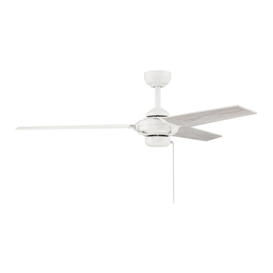
BREES CEILING FAN
1
ITEM #4057328
MODEL #BOD52MW3
Español p. 17
ATTACH YOUR RECEIPT HERE
ADJUNTE SU RECIBO AQUÍ
4007498
Advertisement
Chapters
Table of Contents

Related Manuals for Harbor Breeze BOD52MW3


Summary of Contents for Harbor Breeze BOD52MW3
- Page 1 ITEM #4057328 BREES CEILING FAN MODEL #BOD52MW3 Español p. 17 HARBOR BREEZE and logo design are trademarks or registered trademarks of LF, LLC. All rights reserved. ATTACH YOUR RECEIPT HERE ADJUNTE SU RECIBO AQUÍ 4007498 Purchase Date Questions, problems, missing parts? Before returning to your retailer, call our customer service department at 1-888-251-1003, 8 a.m.
-
Page 2: Table Of Contents
TABLE OF CONTENTS Safety Information ......................... 2 Package Contents ......................... 4 Hardware Contents ....................... 5 Preparation ........................... 5 Initial Installation ........................5 Wiring ..........................11 Final Installation ........................12 Operating Instructions ......................13 Care and Maintenance ......................14 Troubleshooting ........................15 Limited Lifetime Warranty .................... - Page 3 SAFETY INFORMATION WARNING WARNING To reduce the risk of fire, electrical shock or personal injury, mount fan to outlet box marked "ACCEPTABLE FOR FAN SUPPORT OF 35 LBS. OR LESS" and use mounting screws provided with the outlet box. Most outlet boxes commonly used for the support of lighting fixtures are not acceptable for fan support and may need to be replaced.
-
Page 4: Package Contents
PACKAGE CONTENTS PART DESCRIPTION PART DESCRIPTION QUANTITY QUANTITY Downrod Canopy Cover Canopy Canopy Mounting Screw (preassembled) Mounting Bracket Pin (preassembled) Motor Housing Clip (preassembled) Yoke Cover Switch Housing Screw Switch Housing (preassembled) Blade Motor Screw/Lock Washer Blade (preassembled) + 1 extra IMPORTANT REMINDER: You must use the parts provided with this fan for proper installation and safety. -
Page 5: Hardware Contents
HARDWARE CONTENTS (shown actual size) Screw Wire Blade Fiber /Lock Washer Connector Screw Blade Washer Pull Chain Qty. 1 extra Qty. 4 Qty. 9 Extension Qty. 9 + 1 extra + 1 extra Qty. 1 PREPARATION Before beginning assembly of product, make sure all parts are present. Place motor on carpet or on foam to avoid damage to finish. - Page 6 INITIAL INSTALLATION Determine mounting method to use. A. Standard mount B. Angle mount IMPORTANT: If using the angle mount, ensure the ceiling angle is not steeper than 19°. NOTE: Flushmount and closemount options are not available for this fan. 19° max. *Helpful Hint: Downrod-style mounting is best suited for ceilings 8 ft.
- Page 7 INITIAL INSTALLATION Remove six motor screws/lock washers (N) from topside of motor housing (D). Then, remove six motor screws/lock washers (N) from underside of motor housing (D). (underside) (topside) DANGER: To reduce the risk of serious bodily injury, DO NOT use power tools to assemble the blades (H).
- Page 8 INITIAL INSTALLATION Align top of blade arm (G) (labeled THIS SIDE UP) with two motor screw holes on topside of motor housing (D) while allowing the bottom of the blade arm (G) to align with the two corresponding motor screw holes on the underside of the motor housing (D).
- Page 9 INITIAL INSTALLATION 10. Slip downrod (A) into motor housing yoke, align holes and re-install pin (K) and clip (L). Tighten set screws in motor housing yoke and then tighten preassembled nut on one of the set screws. Then, slide yoke cover (E) down until it rests on top of motor housing (D).
- Page 10 INITIAL INSTALLATION If you decided to cut back the lead wires in Step 11, strip 3/4 in. of insulation from end of each wire -- white, black, green and blue (if applicable). Twist stripped ends of each strand of wire within the insulation with pliers (not included).
-
Page 11: Wiring
WIRING WARNING: To reduce the risk of fire, electrical shock or personal injury, wire connectors provided with this fan are designed to accept only one 12-gauge house wire and two lead wires from the fan. If your house wire is larger than 12-gauge or there is more than one house wire to connect to the corresponding fan lead wires, consult an electrician for the proper size wire connectors to use. -
Page 12: Final Installation
FINAL INSTALLATION Locate two canopy mounting screws (J) on underside of mounting bracket (C) and remove canopy mounting screw (J) closest to the open end of the mounting bracket (C). Partially loosen the other canopy mounting screw (J). Lift canopy (B) to mounting bracket (C). -
Page 13: Operating Instructions
FINAL INSTRUCTIONS 3. Attach pull chain extension (DD) or custom pull chain extension (sold separately) to fan pull chain. Hardware Used Pull Chain Extension OPERATING INSTRUCTIONS The pull chain, located on the switch housing (F), has four positions to control fan speed. One pull is HIGH, two is MEDIUM, three is LOW and four turns the fan OFF. -
Page 14: Care And Maintenance
OPERATING INSTRUCTIONS 3a. In warmer weather, setting the reverse switch in the LEFT position will result in downward airflow creating a wind chill effect. 3b. In cooler weather, setting the reverse switch in the RIGHT position will result in upward airflow that can help move stagnant, hot air off the ceiling area. -
Page 15: Troubleshooting
TROUBLESHOOTING WARNING: Before beginning work, shut off the power supply to avoid electrical shock. PROBLEM POSSIBLE CAUSE CORRECTIVE ACTION Fan does not move. 1. Reverse switch not engaged. 1. Push switch firmly either left or right. 2. Power is off or fuse is blown. 2. -
Page 16: Limited Lifetime Warranty
LIMITED LIFETIME WARRANTY The distributor warrants this fan to be free from defects in workmanship and materials present at time of shipment from the factory for Lifetime limited from the date of purchase. This warranty applies only to the original purchaser. The distributor agrees to correct any defect at no charge or, at our option, replace the ceiling fan with a comparable or superior model. - Page 17 ARTÍCULO #4057328 VENTILADOR DE TECHO BREES MODELO #BOD52MW3 HARBOR BREEZE y el diseño del logotipo son marcas comerciales o marcas registradas de LF, LLC. Todos los derechos reservados. 4007498 APTO PARA USO EN Fecha de compra LUGARES HÚMEDOS ¿Preguntas, problemas, piezas faltantes? Antes de volver a la tienda, llame a nuestro Departamento de Servicio al Cliente al 1-888-251-1003, de lunes a domingo de 8 a.
-
Page 18: Información De Seguridad
ÍNDICE Información de seguridad....................18 Contenido del paquete ....................20 Aditamentos ........................21 Preparación ........................21 Instalación inicial ......................21 Cableado ........................27 Instalación final ....................... 28 Instrucciones de funcionamiento ..................29 Cuidado y mantenimiento ..................... 30 Solución de problemas ....................31 Garantía limitada de por vida .................. - Page 19 INFORMACIÓN DE SEGURIDAD ADVERTENCIA ADVERTENCIA Para reducir el riesgo de incendio, descargas eléctricas o lesiones personales, monte el ventilador en una caja de salida marcada como “ACCEPTABLE FOR FAN SUPPORT OF 35 LBS. OR LESS” (APTA PARA SOSTENER VENTILADORES DE 15,87 KG O MENOS) y utilice los tornillos de montaje que se proporcionan con la caja de salida.
-
Page 20: Contenido Del Paquete
CONTENIDO DEL PAQUETE PIEZA DESCRIPCIÓN PIEZA DESCRIPCIÓN CANTIDAD CANTIDAD Varilla Cubierta de la base Base Tornillo de montaje de la base (preensamblado) Soporte de montaje Pasador (preensamblado) Carcasa del motor Sujetador (preensamblado) Cubierta de la horquilla Tornillo de la carcasa del Carcasa del interruptor interruptor (preensamblado) Brazo del aspa... -
Page 21: Aditamentos
ADITAMENTOS (se muestran en tamaño real) Tornillo Tornillo Conector Arandela /arandela de para aspa de cables de fibra seguridad para aspa Extensión para la Cant. 9 Cant. 4 cadena de tiro Cant.: + 1 adicional Cant. 9 1 adicional + 1 adicional Cant. - Page 22 INSTALACIÓN INICIAL Determine el método de instalación que utilizará. A. Montaje estándar B. Montaje en ángulo Nota: las opciones de montaje cerrado y de montaje a ras no se encuentran disponibles para este ventilador. IMPORTANTE: si realiza el montaje en ángulo, verifique que el ángulo del techo no tenga una 19°...
- Page 23 INSTALACIÓN INICIAL Retire los seis tornillos del motor/arandelas de seguridad (N) del lado superior de la carcasa del motor (D). Luego, retire los seis tornillos del motor/arandelas de seguridad (N) del lado inferior de la carcasa del motor (D). (lado (lado inferior) superior)
- Page 24 INSTALACIÓN INICIAL Alinee la parte superior del brazo del aspa (G) (etiquetado ESTE LADO HACIA ARRIBA) con dos de los orificios de los tornillos del motor en la parte superior de la carcasa del motor (D) mientras que se alinee la parte inferior del brazo del aspa (G) con los dos orificios de los tornillos del motor correspondientes en la parte inferior de la carcasa del motor (D).
- Page 25 INSTALACIÓN INICIAL 10. Deslice la varilla (A) en la horquilla de la carcasa del motor, alinee los orificios y vuelva a instalar el pasador (K) y el sujetador (L). Apriete los tornillos de fijación en la horquilla de la carcasa del motor y apriete la tuerca previamente ensamblada en uno de los tornillos de fijación.
- Page 26 INSTALACIÓN INICIAL Si decidió acortar los cables conductores en el Paso 11, pele 1,91 cm del aislamiento del extremo de cada cable: blanco, negro, verde y azul (si corresponde). Tuerza los extremos pelados de cada filamento de cable dentro del aislamiento con pinzas (no se incluyen).
-
Page 27: Cableado
CABLEADO ADVERTENCIA: para reducir el riesgo de incendios, descargas eléctricas o lesiones personales, los conectores de cables incluidos con este ventilador están diseñados para soportar solo un cable de la casa de calibre 12 y dos cables conductores del ventilador. Si el cable de la casa es de un calibre superior a 12 o hay más de un cable para conectar a los cables conductores del ventilador correspondientes, consulte a un electricista cuál es el tamaño adecuado de los conectores de cables que debe utilizar. -
Page 28: Instalación Final
INSTALACIÓN FINAL Ubique dos tornillos de montaje de la base (J) debajo del soporte de montaje (C) y retire el tornillo de montaje de la base (J) más cercano al extremo abierto del soporte de montaje (C). Afloje parcialmente el otro tornillo de montaje de la base (J). -
Page 29: Instrucciones De Funcionamiento
INSTALACIÓN FINAL 3. Conecte la extensión para la cadena de tiro (DD) o la extensión para la cadena de tiro personalizada (no incluida) con la cadena de tiro del ventilador. Aditamentos utilizados Extensión para la cadena de tiro INSTRUCCIONES DE FUNCIONAMIENTO La cadena de tiro ubicada en la carcasa del interruptor (F) tiene cuatro posiciones para controlar la velocidad del ventilador. -
Page 30: Cuidado Y Mantenimiento
INSTRUCCIONES DE FUNCIONAMIENTO 3a. En climas más cálidos, configurar el interruptor de reversa en la posición a la IZQUIERDA creará un flujo de aire descendente que generará un efecto de viento refrescante. 3b. En climas más fríos, configurar el interruptor de reversa en la posición a la DERECHA creará... -
Page 31: Solución De Problemas
SOLUCIÓN DE PROBLEMAS ADVERTENCIA: antes de comenzar cualquier trabajo, desconecte el suministro de electricidad para evitar descargas eléctricas. PROBLEMA CAUSA POSIBLE ACCIÓN CORRECTIVA El ventilador 1. El interruptor de reversa no está 1. Mueva el interruptor hacia la derecha no se mueve. activado. -
Page 32: Garantía Limitada De Por Vida
GARANTÍA LIMITADA DE POR VIDA El distribuidor garantiza que este ventilador no presenta defectos en la mano de obra ni en los materiales presentes al momento del transporte desde la fábrica durante un período limitado de por vida a partir de la fecha de compra. Esta garantía es válida solo para el comprador original. El distribuidor acepta reparar cualquier defecto sin cargo o, según nuestro criterio, remplazar el ventilador de techo por un modelo comparable o superior.
Need help?
Do you have a question about the BOD52MW3 and is the answer not in the manual?
Questions and answers