Table of Contents
Advertisement
Quick Links
Harbor Breeze® is a registered trademark
of LF, LLC. All Rights Reserved.
ATTACH YOUR RECEIPT HERE
Serial Number
Questions, problems, missing parts? Before returning to your retailer, call our customer
service department at
5 p.m., EST, Friday.
PH18432
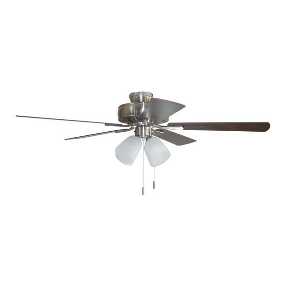
GRACE BAY CEILING FAN
Purchase Date
1-800-643-0067, 8 a.m. - 6 p.m., EST, Monday - Thursday, 8 a.m. -
1
ITEM #0883808
0883807
MODEL #BDB52BNK5L
BDB52OSB5L
Español p. 20
Advertisement
Table of Contents

Related Manuals for Harbor Breeze BDB52BNK5L


Summary of Contents for Harbor Breeze BDB52BNK5L
- Page 1 ITEM #0883808 0883807 GRACE BAY CEILING FAN MODEL #BDB52BNK5L BDB52OSB5L Harbor Breeze® is a registered trademark of LF, LLC. All Rights Reserved. Español p. 20 ATTACH YOUR RECEIPT HERE Serial Number Purchase Date Questions, problems, missing parts? Before returning to your retailer, call our customer service department at 1-800-643-0067, 8 a.m.
-
Page 2: Table Of Contents
TABLE OF CONTENTS Safety Information .......................2 Package Contents .......................4 Hardware Contents ..........................5 Preparation ..........................5 Initial Installation ........................6 Downrod-Style Fan Mounting ....................8 Closemount-Style Fan Mounting ..................10 Wiring ..........................11 Final Installation .........................13 Operating Instructions .......................16 Care and Maintenance ......................17 Troubleshooting........................18 Limited Lifetime Warranty ....................19 Replacement Parts List .....................19 SAFETY INFORMATION READ AND SAVE THESE INSTRUCTIONS... -
Page 3: Safety Information
SAFETY INFORMATION DANGER When using an existing outlet box, make sure the outlet box is securely attached to the building structure and can support the full weight of the fan. Failure to do this can result in serious injury or death. -
Page 4: Package Contents
PACKAGE CONTENTS PART DESCRIPTION QUANTITY PART DESCRIPTION QUANTITY Downrod Canopy Mounting Screw (preassembled) Canopy Pin (preassembled) Mounting Bracket Clip (preassembled) (preassembled) Star Washer Motor Housing (preassembled) Glass Shade Light Kit Fitter Screw Blade (preassembled) Blade Arm Light Kit Fitter Balancing Kit Socket Ring Motor Screw (preassembled) -
Page 5: Hardware Contents
HARDWARE CONTENTS (shown actual size) Blade Fiber Screw Blade Washer Wire Qty. 15 Connector + 1 extra Qty. 15 Pull Chain + 1 extra Qty. 4 Extension Qty. 2 PREPARATION Before beginning assembly of product, make sure all parts are present. Place motor on carpet or on foam to avoid damage to finish. -
Page 6: Initial Installation
INITIAL INSTALLATION Turn off circuit breakers and wall switch to the fan supply line leads. DANGER: Failure to disconnect power supply prior to installation may result in serious injury or death. Determine mounting method to use. A. Downrod mount (standard or angled ceiling) B. - Page 7 INITIAL INSTALLATION 4a. Loosen canopy mounting screws (L) in slotted holes of canopy (B) and remove the other two canopy mounting screws (L) and star washers (O). Save for later use. Remove mounting bracket (C) from canopy (B). Secure mounting bracket (C) to outlet box (not STANDARD ANGLE MOUNT MOUNT...
-
Page 8: Downrod-Style Fan Mounting
DOWNROD-STYLE FAN MOUNTING Remove pin (M) and clip (N) from downrod (A). Partially loosen preassembled set screws and nut in yoke at top of motor housing (D). Set Screw and Nut Yoke 2. Insert downrod (A) through canopy (B). Thread wires from motor housing (D) up through downrod (A). - Page 9 DOWNROD-STYLE FAN MOUNTING Depending on the length of downrod you use, you may need to cut the lead wires back to simplify the wiring. If you decide to cut back the lead wires, it is suggested you do so in the following manner: Ball Take the lead wires and make sure you have...
- Page 10 CLOSEMOUNT-STYLE FAN MOUNTNG Remove preassembled canopy cover from bottom of canopy (B). NOTE: It may be necessary to use a screwdriver (not included) to remove the canopy cover by tapping on the canopy cover from the inside of the canopy (B). NOTE: The downrod (A) and canopy cover are not used in this type of installation.
-
Page 11: Closemount-Style Fan Mounting
CLOSEMOUNT-STYLE FAN MOUNTING Temporarily hang fan on the tab on the mounting bracket (C) using one of the non-slotted holes in the canopy (B). WIRING WARNING: To reduce the risk of fire, electrical shock, or personal injury, wire connectors provided with this fan are designed to accept only one 12-gauge house wire and two lead wires from the fan. -
Page 12: Wiring
WIRING 1b. FAN CONTROLLED BY PULL CHAIN, FAN CONTROLLED BY PULL CHAIN, LIGHT BY WALL SWITCH FAN AND LIGHT CONTROLLED BY TWO WALL SWITCHES LIGHT BY WALL SWITCH: If you intend to control the fan light with a separate wall switch, 120V POWER connect BLACK wire from fan to BLACK wire FROM CEILING... -
Page 13: Final Installation
FINAL INSTALLATION Lift canopy (B) to mounting bracket (C) and align slotted holes in canopy (B) with loosened canopy mounting screws (L) in mounting Closemount Downrod bracket (C). Twist canopy (B) to lock, then Option Option insert the two canopy mounting screws (L) and star washers (O) previously removed (Step 4a, page 7). - Page 14 FINAL INSTALLATION 4. Remove three preassembled light kit fitter screws (P) from light kit fitter (Q). Locate BLUE (or BLACK) and WHITE wires in switch housing preassembled on motor housing (D) labeled FOR LIGHT KIT CONNECTION and remove plastic that holds these two wires together. Switch Housing BLUE (or BLACK)
- Page 15 FINAL INSTALLATION Remove socket rings (R) from sockets on light kit fitter (Q). Attach glass shades (E) to sockets, securing with socket rings (R). WARNING: Do not overtighten socket rings (R) as glass may crack or break. Socket 8. Install bulbs (J). WARNING: When replacing bulbs, allow bulb(s) and glass shade(s) to cool down before touching them.
-
Page 16: Operating Instructions
OPERATING INSTRUCTIONS The pull chain located on the switch housing (labeled FAN) has four positions to control fan speed. One pull is HIGH, two is MEDIUM, three is LOW and four turns the fan OFF. Switch Housing 2. The pull chain located in the middle (labeled LIGHT) is used to turn the lights ON or OFF. -
Page 17: Care And Maintenance
OPERATING INSTRUCTIONS 3A. In warmer weather, setting the reverse switch in the DOWN position will result in downward airflow creating a wind chill effect. 3B. In cooler weather, setting the reverse switch in the UP position will result in upward airflow that can help move stagnant, hot air off the ceiling area. -
Page 18: Troubleshooting
TROUBLESHOOTING WARNING: Before beginning work, shut off the power supply to avoid electrical shock. PROBLEM POSSIBLE CAUSE CORRECTIVE ACTION Fan does not move. 1. Reverse switch not engaged. 1. Push switch firmly either up or down. 2. Power is off or fuse is blown. 2. -
Page 19: Limited Lifetime Warranty
LIMITED LIFETIME WARRANTY The distributor warrants this fan to be free from defects in workmanship and materials present at time of shipment from the factory for Lifetime limited from the date of purchase. This warranty applies only to the original purchaser. The distributor agrees to correct any defect at no charge or, at our option, replace the ceiling fan with a comparable or superior model.
Need help?
Do you have a question about the BDB52BNK5L and is the answer not in the manual?
Questions and answers