Table of Contents
Advertisement
Available languages
Available languages
Harbor Breeze® is a registered trademark of
LF, LLC. All Rights Reserved.
ATTACH YOUR RECEIPT HERE
Serial Number
Questions, problems, missing parts? Before returning to your retailer, call or contact our
customer service department at 1-800-527-1292, 8:30 a.m. - 5:00 p.m., CST, Monday - Friday.
Purchase Date
1
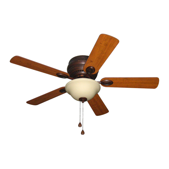
MAYFIELD CEILING FAN
MODEL #BTH44ABZC5C
ITEM #0331094
0331096
BTH44BNK5C
Español p. 18
E124404
Advertisement
Chapters
Table of Contents

Subscribe to Our Youtube Channel
Related Manuals for Harbor Breeze BTH44ABZC5C


Summary of Contents for Harbor Breeze BTH44ABZC5C
- Page 1 ITEM #0331094 0331096 MAYFIELD CEILING FAN Harbor Breeze® is a registered trademark of MODEL #BTH44ABZC5C LF, LLC. All Rights Reserved. BTH44BNK5C Español p. 18 ATTACH YOUR RECEIPT HERE Serial Number E124404 Purchase Date Questions, problems, missing parts? Before returning to your retailer, call or contact our...
-
Page 2: Table Of Contents
TABLE OF CONTENTS Safety Information ........………………………………………………...……..2 - 3 Package Contents ..……………………………………………………………..….….....4 Hardware Contents ........................5 Preparation ....….…………………..……………………….…………….………………..5 Initial Installation ....….……………..……………………….……….…..…......6 - 7 Wiring .........……………………........…………....7 - 9 Final Installation ….…………….……………………….…………….……....……9 - 12 Installing Fan Without Included Light Kit (Optional) .............12 - 13 Operation Instructions ............……………………………..13 - 14 Care and Maintenance …….……………………………………………………..…....14... -
Page 3: Safety Information
SAFETY INFORMATION WARNINGS To reduce the risk of fire, electrical shock, or personal injury, mount fan to outlet box marked "ACCEPTABLE FOR FAN SUPPORT OF 15.9 KG (35 LBS) OR LESS" and use mounting screws provided with the outlet box. Most outlet boxes commonly used for the support of lighting fixtures are not acceptable for fan support and may need to be replaced. -
Page 4: Package Contents
PACKAGE CONTENTS PART DESCRIPTION QUANTITY PART DESCRIPTION QUANTITY Motor Screw Mounting Bracket (preassembled) Motor Housing Lock Washer Motor Assembly (preassembled) Light Kit Fitter Hex Nut (preassembled) Glass Shade Lock Washer Pull Chain Extension (preassembled) Blade Mounting Bracket Screw Finial Plate (preassembled) Finial Star Washer... -
Page 5: Hardware Contents
HARDWARE CONTENTS (shown actual size) Blade Fiber Screw Blade E3 Wire Washer Connector Qty. 15 Qty. 15 Qty. 4 PREPARATION Before beginning assembly and installation of product, make sure all parts are present. Compare parts with package contents list and hardware contents above. If any part is missing or damaged, do not attempt to assemble the product. -
Page 6: Initial Installation
INITIAL INSTALLATION Turn off circuit breakers and wall switch to the fan supply line leads. (Fig. 1) DANGER: Failure to disconnect power supply prior to installation may result in serious injury or death. Check to make sure blades (G) are at least 30 in. from any obstruction and at least 7 ft. -
Page 7: Wiring
INITIAL INSTALLATION Install ball end of motor assembly (C) into mounting bracket (A) opening. Align slot in ball with tab in mounting bracket (A). (Fig. 5) Slot DANGER: Failure to align slot in ball with Ball tab in mounting bracket (A) may result in serious injury or death. - Page 8 WIRING Choose wiring diagram (Fig. 1A, Fig. 1B or Fig. 1C) FAN AND LIGHT CONTROLLED BY PULL CHAINS that fits your situation and make appropriate wiring connections as follows: [NOTE: For each wire BLACK connection below, use one of the wire connectors WHITE 120 V Power FROM...
-
Page 9: Final Installation
WIRING Wrap electrical tape around each individual wire connector (CC) down to the wire as shown in Fig. 2. WARNING: Make sure no bare wire or wire strands are visible after making connections. Place green and white connections on opposite side of box from the black and blue (if applicable) connections. -
Page 10: N Motor Screw
FINAL INSTALLATION Partially insert three blade screws (AA), along with three fiber blade washers (BB), into holes in blade (G) to attach blade arm (J) to blade (G). Then, tighten each blade screw (AA) starting with the one in the middle. (Fig. 2) Repeat with remaining blades (G). - Page 11 FINAL INSTALLATION Locate BLUE (or BLACK) and WHITE wires in switch housing labeled FOR LIGHT and remove plastic that holds these two wires together. Also, remove molex safety caps from bottom of BLUE (or BLACK) and WHITE wires. It may be Switch necessary to pull firmly in order to remove molex Molex...
-
Page 12: Installing Fan Without Included Light Kit (Optional)
FINAL INSTALLATION Locate rubber washer (T), finial plate (H), and finial (I) that were removed in Step 4. Place rubber washer (T) inside glass shade (E) over center hole. Raise glass shade (E) in order to guide pull chains through corresponding holes at the bottom of the glass shade (E). -
Page 13: Operation Instructions
INSTALLING FAN WITHOUT INCLUDED LIGHT KIT (OPTIONAL) Locate cap (K) in one of the hardware packs and place cap (K) firmly in hole in middle of switch housing cap. Align holes in switch housing cap with Switch holes in switch housing and secure switch housing Housing cap with three screws that were removed in Step 4 of “Final Installation”... -
Page 14: Care And Maintenance
OPERATION INSTRUCTIONS Use the fan reverse switch, located on the switch Switch housing, to optimize your fan for seasonal Housing performance. (Fig. 3) A ceiling fan will allow you to raise your thermostat setting in summer and lower your thermostat setting in winter without feeling a difference in your comfort. -
Page 15: Troubleshooting
TROUBLESHOOTING If you have any questions regarding the product please call customer service at 1-800-527-1292, 8:30 a.m. - 5 p.m., CST, Monday - Friday. Warning: Before beginning work, shut off the power supply to avoid electrical shock. PROBLEM POSSIBLE CAUSE CORRECTIVE ACTION Fan does not move. -
Page 16: Warranty
WARRANTY LIMITED LIFETIME WARRANTY: Litex Industries warrants this fan to be free from defects in workmanship and materials present at time of shipment from the factory for Lifetime limited from the date of purchase. This warranty applies only to the original purchaser. Litex Industries agrees to correct any defect at no charge or, at our option, replace the ceiling fan with a comparable or superior model. -
Page 17: Replacement Parts List
ARTICULO #0331094 0331096 VENTILADOR DE TECHO MAYFIELD Harbor Breeze® es marca registrada de LF, LLC. Reservados todos los derechos. MODELO #BTH44ABZC5C BTH44BNK5C ADJUNTE SU RECIBO AQUI E124404 E124404 Número de serie Fecha de compra ¿Preguntas, problemas, faltan piezas? Antes de regresar a la tienda, llame o póngase en contacto con nuestro departamento de servicio al cliente al 1-800-527-1292, de 8:30 a.m. - Page 18 INDICE DE MATERIAS Información de seguridad ..…………………………………………….....19 - 20 Contenido del paquete ....………………………………………………………..21 Contenido de artículos de ferretería ..................22 Preparación ..........….…………………..………………....22 Instalación inicial ..........……………………………………..23 - 24 Conexión de los cables .........…………………………………….24 - 26 Instalación final ....……………….…………….…….………………….…....26 - 29 El Instalar el ventilador sin el juego de luz incluido (opcional) ...........29 - 30 Instrucciones de funcionamiento...
-
Page 19: Información De Seguridad
INFORMACION DE SEGURIDAD ADVERTENCIAS Para reducir el riesgo de incendio, choque eléctrico o daño corporal, sujete el ventilador a una caja de salida marcada "Aceptable para sostener ventilador de 15,9 Kg. (35 lb) o menos" ("ACCEPTABLE FOR FAN SUPPORT OF 15.9 KG (35 LBS) OR LESS" en inglés) y use los tornillos de montaje proporcionados con la caja de salida. -
Page 20: Contenido Del Paquete
CONTENIDO DEL PAQUETE PIEZA DESCRIPCION CANTIDAD PIEZA DESCRIPCION CANTIDAD Tornillo del motor Soporte de montaje (preensamblado) Bastidor del motor Arandela de seguridad Unidad del motor (preensamblada) Conectador para el juego de Tuerca hexagonal (preensamblada) Pantalla de vidrio Arandela de seguridad Extensión para la cadena de (preensamblada) encendido... -
Page 21: Contenido De Artículos De Ferretería
CONTENIDO DE ARTICULOS DE FERRETERIA (se muestra en tamaño natural) Tornillo Arandela para la de fibra paleta para la Conector paleta para cable Ctd. 15 Ctd. 15 Ctd. 4 PREPARACION Antes de empezar con el ensamblaje e instalación del producto, asegúrese de tener todas las piezas. -
Page 22: Instalación Inicial
INSTALACION INICIAL Apague todos los disyuntores del circuito y el interruptor de pared a la línea de suministro de electricidad del ventilador. (Fig. 1) PELIGRO: El no desconectar el suministro de electricidad antes de la instalación puede resultar en daños graves o la muerte. 2. -
Page 23: Conexión De Los Cables
INSTALACION INICIAL Instale el extremo de la unidad del motor (C) con la bola en la abertura del soporte de montaje (A). Alinee la ranura en la bola con la lengüeta del ranura soporte de montaje (A). (Fig. 5) parte bola PELIGRO: El no alinear la ranura en la bola con saliente... - Page 24 CONEXION DE LOS CABLES Escoja el diagrama de instalación eléctrica (Fig. 1A, Fig. VENTILADOR Y LUZ CONTROLADOS POR CADENAS 1B o Fig. 1C) que corresponde a su situación y haga las conexiones apropiadas según lo que sigue: [NOTA: Para NEGRO cada conexión de cable que se va a hacer a continuación, 120 V cables BLANCO...
-
Page 25: Instalación Final
CONEXION DE LOS CABLES Ponga cinta aislante en cada conector para cable (CC) hasta llegar al cable como se muestra en la Fig. 2. ADVERTENCIA: Asegúrese de que no se vean cables pelados ni filamentos después de hacer las conexiones. Coloque las conexiones verdes y blancas en la caja al lado opuesto de las negras y azules (si aplica). - Page 26 INSTALACION FINAL Parcialmente introduzca tres tornillos para la paleta (AA), junto con tres arandelas de fibra para la paleta (BB), en los agujeros de la paleta (G) para sujetar un brazo para la paleta (J) a una paleta (G). Luego, apriete cada tornillo para la paleta (AA), empezando con el de en medio.
- Page 27 INSTALACION FINAL Localice los cables AZUL (o NEGRO) y BLANCO en la caja del interruptor etiquetados "FOR LIGHT" (para la luz) y quite el plástico que liga los dos cables. Además, quite las tapas de seguridad tipo “molex” del fondo de los cables AZUL (o NEGRO) y BLANCO. caja del interruptor Puede que sea necesario jalar las tapas de seguridad...
-
Page 28: El Instalar El Ventilador Sin El Juego De Luz Incluido (Opcional)
INSTALACION FINAL Localize la arandela de hule (T), la placa del adorno con rosca (H), y el adorno con rosca (I) que se quitaron en el paso 4. Ponga la arandela de hule (T) dentro de la pantalla de vidrio (E) encima del agujero de en medio. Levante la pantalla de vidrio (E) para guiar las cadenas de encendido por los agujeros en la parte inferior de la pantalla de vidrio (E). -
Page 29: Instrucciones De Funcionamiento
EL INSTALAR EL VENTILADOR SIN EL JUEGO DE LUZ INCLUIDO (OPCIONAL) Localice la tapa (K) en uno de los paquetes de artículos de ferretería y ponga la tapa (K) firmenente en el agujero de en medio de la cubierta caja del de la caja del interruptor. -
Page 30: Cuidado Y Mantenimiento
INSTRUCCIONES DE FUNCIONAMIENTO Use el interruptor de reversa, localizado en la caja Switch del interruptor, para optimizar el uso del ventilador Housing durante las estaciones del año. (Fig. 3) Un ventilador de techo le permitirá subir el termostato en verano y bajarlo en invierno sin notar una diferencia en su comodidad. -
Page 31: Localización De Fallas
LOCALIZACION DE FALLAS Si tiene alguna pregunta acerca del producto, por favor llame al servicio al cliente al 1-800-527-1292, de 8:30 a.m. a 5:00 p.m., hora central, de lunes a viernes. ADVERTENCIA: Antes de proseguir, desconecte la electricidad, quitando los fusibles o cortando el suministro de energía de los circuitos para evitar un choque eléctrico. -
Page 32: Garantía
LOCALIZACION DE FALLAS PROBLEMA CAUSA POSIBLE ACCION CORRECTIVA 4. No se conectaron correctamente 4. Verifique que se conectaron bien los cables en la caja del interruptor. los cables en la caja del interruptor y, si es necesario, vuelva a conectarlos según las instrucciones en la página 28. -
Page 33: Lista De Piezas De Repuestos
LISTA DE PIEZAS DE REPUESTOS Para piezas de repuesto, llame a nuestro departamento de servicio al cliente al 1-800-527-1292, de 8:30 a.m. a 5:00 p.m., hora central, de lunes a viernes. Al pedir piezas, por favor tenga listo el No. de modelo o No.
Need help?
Do you have a question about the BTH44ABZC5C and is the answer not in the manual?
Questions and answers