Table of Contents
Advertisement
Quick Links
CALDAIA MURALE A GAS PER ESTERNO - ALTO RENDIMENTO - MODULANTE
WALL-HUNG GAS BOILER FOR OUTDOOR INSTALLATION - HIGH EFFICIENCY - MODULATING UNIT
CALDERA MURAL A GAS PARA EXTERIOR - ALTO RENDIMIENTO - MODULANTE
CALDEIRA DE PAREDE A GÁS PARA AMBIENTES EXTERNOS - ALTO RENDIMENTO - MODULÁVEL
MANUALE DI
INSTALLAZIONE E
MANUTENZIONE
AZIENDA CERTIFICATA ISO 9001
INSTALLATION
AND MAINTENANCE
MANUAL
O N
I C
" M
A S
E G
T O
T E N
P R
E R
N S
. U
L ' I
S I G
A K
A L
E M
N U
A S
M A
P L E
T H
S E
T O
" U
E R
L A
O V
N
L E
G A
A R
T E N
E G
L D
T R
U A
E N
R E
A N
N T
" M
R E
L D
V O
U A
T E N
F A
A N
. U
" M
S R
A O
24 MCS W TOP
MANUAL PARA
LA INSTALACIÓN Y
EL MANTENIMIENTO
"
S O
E
A R
D ' U
G N
L E
S E
U A
A N
H E
T T
T E
H A
D
E T
D E
U R
A N
E S
S H
" I
D E
A L
R
S E
A D
E L
E U
I L I D
R I O
A B
U A
A M
U S
A L
"
S O
E U
R O
G A
"
S O
E U
T E
U/IT
MANUAL DE
INSTALAÇÃO E
MANUTENÇÃO
Advertisement
Chapters
Table of Contents

Related Manuals for LAMBORGHINI thin 24 MCS W TOP U/IT


Summary of Contents for LAMBORGHINI thin 24 MCS W TOP U/IT
- Page 1 AZIENDA CERTIFICATA ISO 9001 " D ' U " M T E N L ' I S I G " I I L I D P L E R I O " U " T E N " " M T E N "...
-
Page 2: Table Of Contents
..on an excellent choice. We thank you for the preference accorded to our products. LAMBORGHINI CALORECLIMA has been actively present in Italy and throughout the world since 1959 with a widespread network of agents and concessionary agents to constantly guarantee the presence of our product on the market. -
Page 4: General Instructions
AUTHORISED SKILLED TECHNICIANS. TO ENSURE THAT BOILER IS INSTALLED CORRECTLY AND THAT IT FUNCTIONS PROPERLY, WE RECOMMEND THAT ONLY LAMBORGHINI ACCESSORIES AND SPARE PARTS BE USED. ON NOTICING THE SMELL OF GAS DO NOT TOUCH ANY ELECTRIC SWITCH. OPEN DOORS AND WINDOWS, SHUT OFF THE GAS COCKS. -
Page 5: Description
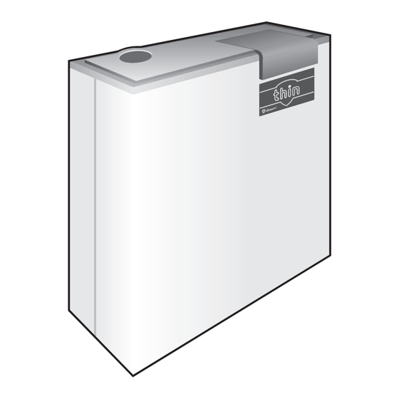
DESCRIPTION The THIN boiler has been designed for outdoor installation in partially protected areas and can operate at winter temperatures as low as –15°C. It is largely intended for installation on balconies and terraces. This unit is practically “invisible” as it is designed to be wall-mounted just 80 mm above the floor. The boiler is equipped with an anti-freeze system designed to protect the heating and domestic hot water circuits;... -
Page 6: Main Components
MAIN COMPONENTS LEGEND Ignition electrodes 15 Instantaneous water-heater Manual air purge valve 16 Hot water circuit drain cock Fumes fan 17 Hot water detector Total safety thermostat 18 Automatic air purge valve Fumes pressure switch 19 Circulating pump Heating detector 20 Heating safety valve 3-way valve 21 Heating circuit drain cock... -
Page 7: Dimensions
DIMENSIONS mm TECHNICAL FEATURES Min. thermal Operating Hot water Thermal capacity Connections capacity pressure supply Expansion Weight MODEL tank Heating Hot water Continuous Min. Main system Hot water system Input Output Input Output circuit circuit supply supply Supply Return Inlet Outlet ∆30ºC min. -
Page 8: Nozzle Calibration
GAS - NOZZLE CALIBRATION The boilers leave the factory calibrated and predisposed to operate with NATURAL GAS and LIQUID GAS. These calibrations are effected without the connection of the compensating joint (Pos. A). For the calibrations to put into effect, see the table related below: Burner Pressure on nozzles mbars Delivery... -
Page 9: Electrical Connections - Wiring Diagrams
ELECTRICAL CONNECTIONS - WIRING DIAGRAMS The boiler must be connected to an earthed, single-phase 220-230V-50 Hz mains supply by means of a three- wire cable, ensuring that connections to the LINE and NEUTRAL terminals are made correctly. A bipolar switch must be used with contacts opening to at least 3 mm. The power lead must only be replaced by another with the following characteristics: “HAR H05 VV-F”... - Page 10 PRINCIPLE DIAGRAM LEGEND Modulating coil R4 relay contact Ignition control unit Honeywell RL2 relay contact Circulating pump Anti-interference resistance Control electrode Lock-out warning light Spark electrode Heating detector Line Hot water/water-heater detector MAX R Max. heating setting SW1 Function selector Neutral TIMER Boiler timer adjustment Fumes pressure switch...
- Page 11 CIRCUIT DIAGRAM NOTE: Check that the microswitches on selector SW1 are as illustrated in the diagram. LEGEND Modulating coil Anti-freeze element Ignition control unit Honeywell Anti-interference resistance Remote control - room thermostat Lock-out warning light Circulating pump Connection card Control electrode Heating detector Spark electrode RX-TX board...
-
Page 12: Installation And Start-Up
INSTALLATION AND START-UP Remove the control unit base-block by levering the two lower hooks (fig. 1). fig. 1 fig. 2 Fix the control unit to the wall via the holes in the base-block. This should be mounted 1.5 m above the floor in an area well away from entry/exit doors, windows or other factors that might influence room temperature readings (fig. -
Page 13: Setting The Time/Day Of The Week
Once the connections have been made power up the boiler and, after the “CON” signal, check that the legend “OFF” appears on the main display and that the time 00:00 on the lower display and the day indicator both appear If the legend “CON”... -
Page 14: Automatic" Temperature Control Mode
G “HOT WATER/HEATING” MODE ( SYMBOLS DISPLAYED) This mode provides both hot water and heating, operated automatically according to requirements. G “HEATING” FUNCTION ( SYMBOL DISPLAYED) This mode enables the boiler for activation of the heating circuit in “Automatic” or “Manual”. When this mode is selected you can adjust heating water temperature and set the on/off times to be used in automatic mode. -
Page 15: Manual" Temperature Control Mode
G COPYING HOURLY PROGRAMMING To speed up programming, you can “paste” the settings for a specific day onto another day. Press V to select the day from which you wish to copy the settings. Press the Copy key within 5 seconds to copy and then press the + and – keys to select the page onto which you intend to “paste”... -
Page 16: Setting The Temperature
SETTING THE TEMPERATURE The control unit allows the user to set 5 basic temperatures in order to provide maximum comfort and maximum system efficiency. G HOT WATER TEMPERATURE This temperature may be set with either the Hot water or Hot water/Heating function enabled. To set press the key and the presently set temperature will appear on the display. -
Page 17: Viewing Main Boiler Parameters
To set press the key: the presently set temperature will appear on the display. Now hold the key down and press the – or + keys to modify the temperature setting as desired. Release the key to memorise the new setting. VIEWING MAIN BOILER PARAMETERS Press the key repeatedly to view the main boiler parameters (illustrated below) in sequence. -
Page 18: Re-Establishing Factory Settings And Control Reset
RE-ESTABLISHING FACTORY SETTINGS AND CONTROL RESET You may wish to re-establish the settings made at the factory: to do so press the key for 10 seconds and the message “Fab” will appear on the display. Going through this procedure resets the following parameters: standard temperature 20°C comfort temperature:... -
Page 19: Installer Settings
INSTALLER SETTINGS The tasks in this section must only be carried out by qualified personnel. Carrying out these procedures wrongly may damage the control unit and boiler or cause them to malfunction. G CONNECTING UP TO THE OUTDOOR TEMPERATURE SENSOR. The control unit can also be fitted with a sensor that monitors outdoor temperature. - Page 20 G CORRECTING ROOM TEMPERATURE MEASUREMENT This allows the user to correct the room temperature detected by the control unit and adapt it to different user needs. The entire correction procedure must be done with the control unit powered and connected to the boiler. Room temperature correction: Press key R and keep it pressed: Press the...
-
Page 21: Hydraulic Connection
HYDRAULIC CONNECTION Fit the supporting hooks and attach the assembly template, moving it up to the wall; fit all the pipes, starting with the end pipe fittings already mounted on the template: system supply, system return, cold water, hot water, any gas pipes and electric mains leads with room thermostat. -
Page 22: Hydraulic Circuit
HYDRAULIC CIRCUIT LEGEND 3-way valve 18 Circulating pump HOT WATER OUTLET Lack of water pressure switch 19 Heating circuit drain cock COLD WATER INLET Burner 20 Heating safety valve SYSTEM SUPPLY 10 Fumes exchanger 21 Hydrometer RETURN 11 Fumes pressure switch 22 Filling cock Hot water circuit drain cock 12 Fumes fan... -
Page 23: Installation
INSTALLATION To be carried out by qualified personnel. The installation must be in compliance with the stipulations of the law regarding the evacuation of combustion materials according to the REGULATIONS IN FORCE. It is compulsory that the gas fumes evacuation is effected with a pipe of a diameter not less than that required by the boiler and that it comes connected to a flue pipe suitable for the capacity of the installation. -
Page 24: Flue Exhaust Types
FLUE EXHAUST TYPES The boiler must be installed and function outdoors. For installation use only original LAMBORGHINI parts. FAN-FORCED DRAUGHT FLUE EXHAUST KIT To install the forced draught kit insert the funnel 1 (supplied with the boiler) in the fan. Insert the diaphragm 3 and the adhesive seal 2. -
Page 25: Flue Exhaust Connection
FLUE EXHAUST CONNECTION FLUE EXHAUST CONNECTION TO FAN-FORCED DRAUGHT VERSION (B22) The boiler is envisaged being connected to a chimney and/or a flue pipe with the following specification: G of being sealed airtight, as with the connection to the chimney itself; G of being of suitable material;... - Page 26 FUMES EVACUATION/AIR INTAKE Concentric flue pipe, from the terrace Fan-forced draught (B22), from a flue pipe Double pipe from separate flues Concentric, connected to concentric flues Fan-forced draught (B22), from the roof For positioning and for distances of draught terminals from windows, doors, etc. see regulations in force.
-
Page 27: Flue Exhaust Installation
ELBOW FITTED AT 90° Flue exhaust for fan-forced draught version (B22) 0,6 m 0,3 m Concentric flue exhaust 0,5 m Double flue pipe (intake/exhaust) 0,6 m 0,3 m ATTENTION: Use only air intake/ fumes evacuation kit produced by Lamborghini Caloreclima. -
Page 28: Adjustments
ADJUSTMENTS The boiler allows to adapt the heating thermal power (without involving the adjustment of the capacity available for the production of hot water) to the thermal need of the rooms to be heated. When leaving the factory all boilers are set to 70% of their maximum output. To adapt the boiler to the thermal power needed by the plant it is necessary to carry out the following operations: G Insert a manometer in the pressure tube (G) G Electrically feed the gas valve with the boiler on in the WINTER position... -
Page 29: Switching Off
SWITCHING OFF BOILER SWITCHED OFF FOR A PROLONGED PERIOD AND INSTALLED INSIDE If the boiler should remain inactive at length close the gas cock and remove the electrical current from the appliance. BOILER SWITCHED OFF FOR A PROLONGED PERIOD AND INSTALLED OUTSIDE. Where there is risk of sub-zero temperatures and thus ice formation empty the hot water circuit and leave the heating circuit filled with the anti-freeze liquid. -
Page 30: Operation With Different Types Of Gas
OPERATION WITH DIFFERENT TYPES OF GAS CONVERSION FROM NATURAL GAS TO LIQUID GAS Proceed with burner jets replacement. Insert the diaphragm (I) included in the kit. Also replace the spring (C) under the rod of the coil (E), checking that it is assembled the right way round. Switch the bridge on the modulation board from NATURAL GAS to the B-P position. -
Page 31: Anti-Freeze Kit (On Request)
ANTI-FREEZE KIT (ON REQUEST) The THIN boiler is fitted as standard with an anti-freeze device that protects the hydraulic circuit. This device is tripped when the temperature falls to about 6°C. The hot water circuit can be provided with even better protection by installing an ANTI-FREEZE KIT which starts functioning at 4°C. -
Page 32: Fault-Finding Chart
FAULT-FINDING CHART FAULT CAUSE RIMEDY A. Gas cock closed A. Open gas cock 1 NO IGNITION B. “Off” button locked B. Reset by pressing C. No flame detection C. Nautral and phase inverted D. No ignition spark D. Call technical service E. - Page 33 TRATTAMENTO ACQUA CONDIZIONAMENTO Le illustrazioni e i dati riportati sono indicativi e non impegnano. La LAMBORGHINI si riserva il diritto di apportare senza obbligo di preavviso tutte le modifiche che ritiene più opportuno per l'evoluzione del prodotto. The illustrations and data given are indicative and are not binding on the manufacturer. LAMBORGHINI reserves the right to make those changes, considered necessary, for the improvement of the product without forwaming the customer.
- Page 34 AZIENDA CERTIFICATA ISO 9001 CALDAIA MURALE A GAS ALTO RENDIMENTO - MODULANTE MANUALE PER L‘UTENTE Alla cortese attenzione del sig. INSTALLATORE: Consegnare il presente manuale d’uso all’UTENTE WALL-HUNG GAS BOILER FOR HIGH EFFICIENCY - MODULATING USER MANUAL For the attention of the INSTALLATION TECHNICIAN: make sure that this manual is handed over to the USER CALDERA MURAL A GAS ALTO RENDIMIENTO - MODULANTE...
- Page 35 Read carefully this guide in order to know any detail concerning the product’s operation system. The “LAMBORGHINI SERVICE” after-sales centres are at your disposal to ensure QUALIFIED MAINTENANCE and PROMPT SERVICE. LAMBORGHINI CALORECLIMA...
-
Page 36: General Instructions
ALL INSTALLATION, MAINTENANCE AND GAS CONVERSION OPERATIONS MUST BE CARRIED OUT BY AUTHORISED SKILLED TECHNICIANS. To ensure that boiler is installed correctly and that it functions properly, we recommend that only Lamborghini accessories and spare parts be used. On noticing the smell of gas do not touch any electric switch. Open doors and windows, shut off the gas cocks. -
Page 37: Instructions For The Use
Call exclusively professionally qualified personnel. Any repair must be carried out by an after-sale service centre “LAMBORGHINI SERVICE” authorised by the manufacturing firm, and using original replacements exclusively. Non-observance of the above could compromise the guarantee and the safety of the appliance. -
Page 38: Checks And Maintenance
CHECKS AND MAINTENANCE G Before starting up the boiler ask qualified personnel “LAMBORGHINI SERVICE” to check: a) that the data on the information plate corresponds to that required by the gas, electrical and water supply networks; b) that the pipes which branch off from the boiler are lined with suitable thermally-insulated sheathing;... -
Page 39: Setting The Time/Day Of The Week
SETTING THE TIME/DAY OF THE WEEK You can set the clock time and the day of the week in any mode. To begin setting press the H/Day key once. The minute figures will then start flashing. Press the + and – keys to set the minutes and then press H/Day again to confirm. The hour figures on the display will now flash. -
Page 40: Automatic" Temperature Control Mode
“AUTOMATIC” TEMPERATURE CONTROL MODE The control unit has a daily/weekly timer that automatically adjusts room temperature to “comfort” or “low temperature” values over a 24 hour period, with independent settings for each of the seven days. To enable automatic operation press the key and the symbol will be displayed. -
Page 41: Manual" Temperature Control Mode
NOTE: Immediately after setting the date and the day (section 2) a factory-set default programme is activated. This programme is given in the table below. Standard Programme from Monday to Friday Saturday and Sunday Low temp. 23:00+06:00 23:00+08:00 Comfort temp. 06:00+09:00 08:00+23:00 Low temp. -
Page 42: Viewing Main Boiler Parameters
Release the key to memorise the new setting. Should the boiler be equipped with an outdoor sensor, the values being displayed and set are outdoor temperature and heating water temperature. G STANDARD ROOM TEMPERATURE Sets the standard Manual temperature in either the Heating or Hot water/Heating modes. Press the –... -
Page 43: Re-Establishing Factory Settings And Control Reset
The appearance of the symbol on the display shows that the user has requested Hot Water or Heating. RE-ESTABLISHING FACTORY SETTINGS AND CONTROL RESET You may wish to re-establish the settings made at the factory: to do so press the key for 10 seconds and the message “Fab”... -
Page 44: Installer Settings
INSTALLER SETTINGS The tasks in this section must only be carried out by qualified personnel. Carrying out these procedures wrongly may damage the control unit and boiler or cause them to malfunction. G CONNECTING UP TO THE OUTDOOR TEMPERATURE SENSOR. The control unit can also be fitted with a sensor that monitors outdoor temperature. - Page 45 G CORRECTING ROOM TEMPERATURE MEASUREMENT This allows the user to correct the room temperature detected by the control unit and adapt it to different user needs. The entire correction procedure must be done with the control unit powered and connected to the boiler. Room temperature correction: Press key R and keep it pressed: Press the...
-
Page 46: Fault-Finding Chart
FAULT-FINDING CHART FAULT CAUSE REMEDY A. Gas cock closed A. Open gas cock 1 NO IGNITION B. “Off” button locked B. Reset by pressing C. No flame detection C. Neutral and phase inverted D. No ignition spark D. Call technical service E. - Page 47 CALDAIE MURALI E TERRA A GAS GRUPPI TERMICI IN GHISA E IN ACCIAIO GENERATORI DI ARIA CALDA TRATTAMENTO ACQUA CONDIZIONAMENTO LAMBORGHINI CALOR S.p.A. VIA STATALE, 342 44040 DOSSO (FERRARA) ITALIA TEL. ITALIA 0532/359811 - EXPORT 0532/359913 FAX ITALIA 0532/359952 - EXPORT 0532/359947 11/00 Cod.
Need help?
Do you have a question about the thin 24 MCS W TOP U/IT and is the answer not in the manual?
Questions and answers