Table of Contents
Advertisement
Quick Links
Advertisement
Table of Contents

Related Manuals for Rugged CCTV Vanguard-700


Summary of Contents for Rugged CCTV Vanguard-700
- Page 1 Vanguard-700 Outdoor Camera INSTRUCTION MANUAL...
-
Page 2: Table Of Contents
CONTENTS WARNING & CAUTION GENERAL FEATURES NAME OF EACH PART INSTALLATION CONNECTION SPECIFICATIONS OSD MENU SETTING TROUBLESHOOTING DIMENSIONS... -
Page 3: Warning & Caution
WARNING & CAUTION If you fail to read this information and handle the product incorrectly, death or serious injury may occur. The unit should be installed by the trained Personnel. Switch off immediately if the product emits smoke or abnormal heat. Never install the product in area exposed to oil or gas. - Page 4 WARNING & CAUTION CAUTION RISK OF ELECTRIC SHOCK DO NOT OPEN CAUTION: TO REDUCE THE RISK OF ELECTRIC SHOCK, DO NOT REMOVE COVER (OR BACK). NO USER SERVICEABLE PARTS INSIDE. REFER SERVICING TO QUALIFIED SERVICE PERSONNEL. This symbol is intended to alert the user to the presence of un-insulated "dangerous voltage"...
-
Page 5: General Features
GENERAL FEATURES IP-67 rated waterproof frame housing An ideal waterproof frame housing suitable for the outdoor circumstance. 3-Axis bracket (Wall, Ceiling, Pole mount available) This 3-Axis bracket enable you to install easily anywhere. Compatible with a junction box (option) It can compatible with a junction box, therefore easy to install. Adjustable Zoom &... - Page 6 GENERAL FEATURES High Resolution By adopting a diagonal 6mm(1/3") SONY EXVIEW HAD CCD II, the camera produces clear picture quality with a horizontal resolution of 700 TV line color, and 800 TV line B/W (960H Type) Low Light Sensitivity By adapting unique digital processing technology, It can clearly distinguish the outline and color of a subject in 0.0001Lux(B/W for Sens-up x256) low illumination environments.
-
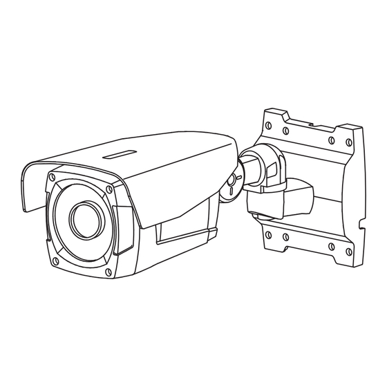
Page 7: Name Of Each Part
NAME OF EACH PART FIG.1 1. Sunvisor 2. Camera Body 3. Function Cover 4. Function Part 5. IR LED Lamp 6. Lens 7. Camera Bracket 8. Lens Control Lever 9. Set Screw groove for Sunvisor 10. X-Axis Set Screw 11. Y-Axis Set Screw 12. - Page 8 NAME OF EACH PART FUNCTION PART FIG.2 FUNCTION Extra Video Out CVBS Output IR Gain IR Gain Control 3 Lux / 6 Lux CDS Sensitivity Control ON / OFF IR LED ON / OFF OSD Button Up, Down, Set, Left, Right...
-
Page 9: Installation
INSTALLATION Calblock( 6x30) Template Label 81mm Hole Diameter : 6mm Depth : 30mm FIG.4 FIG.3 Seal Tape FIG.5 1. When you need to install a camera on the surface of a concrete wall, you can drill a hole like Fig.3 exactly by using a Template Card offered by accessory. 2. - Page 10 INSTALLATION Wrench 2mm Screw 4x30 Wrench 3mm FIG.6 FIG.7 FIG.8 4. Like Fig.6, after put the cable connector part into the bracket, please fix the bracket on the wall by use of screws. 5. Like Fig.7, after set the camera to desired direction, please fix tightly by L-Wrench. 6.
- Page 11 INSTALLATION How to install Junction Box Calblock( 6x30) Template Label 46mm Hole Diameter : 6mm Depth : 30mm FIG.9 FIG.10 Screw 4x30 FIG.11 1. Like Fig.9, please make a screw sign hole on the wall for fixation of Junction Box by use of offered Template Label.
- Page 12 INSTALLATION Screw M4x60 Nut M4 Screw M4x20 FIG.12 FIG.13 4. Joint the Camera bracket to the Junction Box, then put the Screw into a Hinge part after that tighten by Nut. (Fig.12) 5. Connect a cable and like Fig.13, please join Bracket part. (Please refer to Page 12 regarding cable connection) How to install Ceiling &...
-
Page 13: Connection
CONNECTION DUAL POWER TYPE *A power source connection is nonpolar. FIG.16 1. Terminal Block (Accessory) 2. DC Jack Cable (Accessory) 3. Adaptor (DC12V or AC24V) 4. Video Output (CVBS) 5. Seal Tape *A power source connection is nonpolar. DC12V POWER TYPE FIG.17 1. -
Page 14: Specifications
SPECIFICATIONS (760H Type) TV SYSTEM NTSC Total pixels 811(H) x 508(V) 795(H) x 595(V) Effective pixels 768(H) x 494(V) 752(H) x 582(V) Frequency 15.734[KHz] (H) / 59.94[Hz] (V) 15.625[KHz] (H) / 50[Hz] (V) Auto/FLK/Manual(1/60~100,000 sec) Auto/FLK/Manual(1/50~100,000 sec) NEXT CHIP HAWK-II 1/3 inch SONY 760H EXVIEW HAD CCD II Sensor Resolution... - Page 15 SPECIFICATIONS (960H Type) TV SYSTEM NTSC Total pixels 1020(H) x 508(V) 1020(H) x 596(V) Effective pixels 976(H) x 494(V) 976(H) x 582(V) Frequency 15.734[KHz] (H) / 59.94[Hz] (V) 15.625[KHz] (H) / 50[Hz] (V) Auto/FLK/Manual(1/60~100,000 sec) Auto/FLK/Manual(1/50~100,000 sec) NEXT CHIP HAWK-II 1/3 inch SONY 960H EXVIEW HAD CCD II Sensor Resolution...
-
Page 16: Osd Menu Setting
OSD MENU SETTING MENU SUB MENU BRIGHTNESS 0~100 IRIS SPEED LENS VIDEO BRIGHTNESS 0~100 MANUAL AUTO(SHUT.MIN, SHUT.MAX), 1/60(50), FLK, MANUAL(LEVEL1/60, FLK,1/250,1/500, SHUTTER 1/1000,1/2000,1/5000,1/10000,1/20000,1/50000,1/1000000 LOW,MIDDLE,HIGH EXPOSURE SENS-UP x2,x4,x6,x8,x10,x12,x14,x16,x24,x32,x64,x128,x256 AUTO LOW-LEVEL 0~15 D-WDR HIGH-LEVEL 0~15 VALUE LOW, MIDDLE, HIGH AREA SINGLE, DOUBLE DEFAULT BACK LIGHT 0~100... - Page 17 OSD MENU SETTING MENU SUB MENU AREA AREA DISPLAY ON,OFF MOTION 0~100 VALUE ON,OFF MOTION VIEW AREA AREA DISPLAY ON,OFF PRIVACY 0~15 COLOR TRANSFER RANGE x1.0~x32 -100~100 D-ZOOM TILT -100~100 RANGE x2.0~x5.0 POSITION SMART D-ZOOM D-EFFECT SENSITIVITY 0~100 FUNCTION TIME 0~15 ON,OFF FREEZE...
-
Page 18: Troubleshooting
TROUBLESHOOTING PROBLEM SOLUTION No picture Check if the power cable is connected properly. Check if the video cable is connected correctly. Camera with excessive Check if the power supply meets the minimum heat, Abnormal motion requirements and that the power supply is or Black lines on the functioning properly. -
Page 19: Dimensions
DIMENSIONS UNITS:mm... - Page 20 MP86C033...
Need help?
Do you have a question about the Vanguard-700 and is the answer not in the manual?
Questions and answers