
Related Manuals for Rugged CCTV Ruff Ride


Summary of Contents for Rugged CCTV Ruff Ride
-
Page 1: User Manual
USER MANUAL HD Portable All-Condition Rugged PTZ Camera (IR and White Light Versions) - Page 3 Safety Notes Thank You for Choosing Our HD Portable All-Condition Rugged PTZ Camera! When you open the box: 1. Check that the packing and the contents are not visibly damaged. Contact the retailer immediately if any parts are either missing or damaged. 2.
-
Page 4: Table Of Contents
Table of Contents Safety Notes..................... 1 About The Product ..................2 Features ......................2 Functions ......................3 Technical Data ....................6 Preparation ...................... 8 Dip Switch ...................... 8 Initial Power On Test ..................9 Installation Place ..................10 Installation ..................... 11 Fixed Mounts .................... -
Page 5: Safety Notes
Safety Notes --- Important!!! The following important notes must be followed carefully to run the camera and respective accessories in total safety. The camera and relative accessories are called video system in this section. Before installing the camera, please read this manual carefully; when installing please follow instructions of installation indicated in this manual. -
Page 6: About The Product
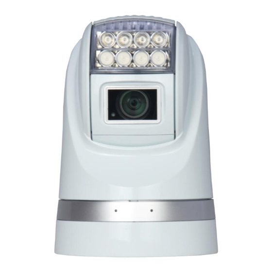
About The Product PAHC series camera is designed for fixed and mobile video surveillance applications, such as marine, law enforcement, army, border patrol, airport, oilfield etc. It consists of: high resolution zoom module, powerful IR or white lighting module, precise PTZ system, optional damping systems. -
Page 7: Functions
About The Product New design of drive system, PTZ positioning precision up to +/-0.05°; Camera address easily changeable via software; Baud rate, protocol self-adaptive; Digital image stabilization; Image flip for stand / ceiling mount; Video freeze; ... -
Page 8: Zoom Control
About The Product Save/Call Preset Preset function is that dome saves current horizontal angle and title angle of pan/tilt, zoom and position parameters into memory. When necessary dome calls these parameters and adjusts Pan/Tilt and camera to that position. User can save and call presets easily and promptly by using keyboard controller or infrared controller. -
Page 9: Auto White Balance
About The Product Auto White Balance Camera can automatically adjust white balance (WB) according to the alteration of background lightness to give a true color image. Back Light Compensation (BLC) If a bright backlight presents, the subjects in the picture may appear dark or as a silhouette. Backlight compensation enhances objects in the center of the picture. -
Page 10: Technical Data
About The Product Technical Data Camera 1/2.8 type solid state Progressive Image Sensor 1/2.8” SONY EX-View HAD CCD Scan CMOS Effective Pixel 1920(H)×1080(V) HD:1080p/30,1080p/25,1080i/60,1080i/50,720p/60,720p/50,720p/30, Video Format 720p/25 SD: PAL/NTSC Video System PAL/NTSC Optical Zoom Digital Zoom Min Illumination 0.4Lux (Lights Off) 0.5Lux (Lights Off) 0.04Lux (Lights On) 0.095Lux (Lights On) - Page 11 About The Product Range 120m Switch Manual General Comm. Interface RS-485 OSD Language English Protocol PELCO-P / PELCO-D(self-adaptive) Baud Rate 2400bps, 4800bps, 9600bps, 19200bps (self-adaptive) Address 0-255 Voltage DC 10.8-28V 12W (Standby) Power 55W (Defogger and lights on) Working Temperature -45℃~+65℃...
-
Page 12: Preparation
Preparation This section contains detailed instructions for installing the camera. These instructions assume that the installer has a good knowledge of installation techniques and is capable of adopting safe installation methods. Dip Switch The factory default is: Camera Address Protocol Baud Rate Pelco D 9600bps... -
Page 13: Initial Power On Test
Preparation Initial Power On Test To ensure the camera works well after installation, please power on it for an initial test with the following steps: 1. Connect the camera with correct power supply; 2. Connect control cable, video cable; 3. Power on the camera; When the camera is powered on, the LED indicators at the front will be on. -
Page 14: Installation Place
Preparation DOME ID:001 PROTOCOL:PELCO-D/P BAUD:9600 SOFTWARE VER: 1.0.0 CAM FAIL Please refer to the following code to check the failures: PAN FAIL Failure of pan initialization TILT FAIL Failure of tilt initialization CAM FAIL Failure of block camera initialization P/T FAIL Failure of pan and tilt initializations T/Z FAIL Failure of tilt and block camera initializations... -
Page 15: Installation
Installation Fixed Mounts The fixed mount provides damping system as optional. Fig. 4: Fixed Mounts (with and w/o damping system) -
Page 16: Installation
Installation Installation To set the baud rate, protocol and camera’s hard address: 1. Remove the PTZ bottom plate; 2. Set DIP Switch for baud rate, protocol and camera address; 3. Fix the bottom plate. Make sure the sealing is well installed. Fig. -
Page 17: Camera Cable Package
Installation Fig. 7: Mount the Installation Plate 7. Fix the camera to the installation plate with a screw. Fig. 8: Fix the Installation Plate Camera Cable Package Connect the cable with the right pins as per following pictures. - Page 18 Installation Fig. 9: Cable Package 6Pin Cable: Pin Definition Video + Power - Power + RS485 - RS485 + Video - There are two red marks each on the plug and socket. Please match them during plugging. [Note] Please make sure the camera is working with a right power supply. Wrong cable connection may cause damage to the device.
-
Page 19: Menu Settings
MENU SETTINGS Menu Configuration <VIDEO> FORMAT 1080i50, 1080i60, 1080p25, 1080p30, Refer to 720p50, 720p60, 720p25, 720p30 Page 17 WIDE DYNAMIC ON, OFF, AUTO 1, 2, 3, 4, 5, OFF FOCUS MANUAL , AUTO FREEZE ON, OFF DIGI ZOOM ON, OFF ON, OFF EXPOSURE…... -
Page 20: Menu Explanation
Menu settings Menu Explanation Main Menu Press MENU button to enter / exit menu. ❶ <MENU> VIDEO ❷ PAN TILT SYSTEM REBOOT RESTORE DEFAULTS ❶ Menu Title It displays currently selected menu entries. ❷ Menu Entries It displays options under current menu title. Press button to select among menu options, once font of options turned from white color to yellow color, it indicates the menu has been elected, press OK button to get into this... - Page 21 Menu settings VIDEO VIDEO menu is used to change video value. <VIDEO> FORMAT 1080P25 WIDE DYNAMIC FOCUS AUTO FREEZE DIGI ZOOM EXPOSURE… Option Value Explanation When HD video output format is set as 1080i60, 720p60, 1080p30, 720p30, relative SD video format is 1080i50, 1080i60, 1080p25, NTSC;...
- Page 22 Menu settings EXPOSURE <EXPOSURE> MODE FULL AUTO SLOW SHT.LIMIT Option Value Explanation FULL AUTO, MANUAL, MODE Switch exposure mode. SHUTTER PRI, IRIS PRI FULL AUTO: Gain, Shutter Speed and Iris value are adjusted automatically accordingly to working environment. SLOW SHT. LIMIT: this option sits under “Full Auto”, there are On and Off options. MANUAL: manually adjust Gain, Shutter Speed and Iris GAIN: -3, 0, +2, +4, +6, +8, +10, +12, +14, +16, +18, +20, +22, +24, +26, +28.
-
Page 23: Pan Tilt
Menu settings PAN TILT PAN/TILT is used to change pan/tilt/zoom value, available options: <PAN TILT> LIGHT WIPER DAY/NIGHT AUTO PRESET… CRUISE… FRAME SCAN… RANDOM SCAN INTERVAL/S POWER UP ACTION NONE PAN/TILT SPEED Option Value Explanation This option sits under manual LIGHT ON, OFF DAY/NIGHT... - Page 24 Menu settings PRESET <PRESET> NUM TILT ZOOM LABEL EDIT DELETE Option Value Explanation 0~255 Preset number System information Pan position TILT System information Tilt position ZOOM System information Zoom position LABEL System information Preset label EDIT YES, NO Edit preset DELETE YES, NO Delete preset...
- Page 25 Menu settings Option Value Explanation PATH 1,2,3,4 Duration (in seconds) of the dwelling INTERVAL/S 4~13s time on each preset. This menu item is used to enable each of SELECT PRESET TO CRUISE System information the preset positions used in the cruise cycle.
-
Page 26: Restore Factory Defaults
Menu settings Option Value Explanation ADDRESS 0~255 Reboot is necessary after switch. PROTOCOL System information BAUDRATE System information VIDEO FORMAT System information MOUNT MODE CEILING, STAND DISPLAY INFO ON, OFF Show or hide the information of PTZ SOFTWARE VER System information REBOOT Choose REBOOT option, press OPEN to confirm, the indication will appear: <REBOOT>... -
Page 27: Operation
Operation Special Control Panel Commands The camera can be programmed and operated using various quick control panel commands. Default Preset Number Function Value Manual switch between color mode (with light off) and mono GO TO 21 mode (with light on) √... -
Page 28: Operation
Operation GO TO 65 Increase the camera shutter speed GO TO 66 Decrease the camera shutter speed GO TO 67 Turn on cruise 2 GO TO 68 Turn on cruise 3 GO TO 69 Turn on cruise 4 GO TO 70 Turn on white lights only (only for white light models) √... - Page 29 Operation Image Freeze Call Preset 28 to turn on/off the function. When it is on, during a regular preset call (see following picture), the video will be frozen at point A till Point B. At Point B, the video will be displayed normally.
- Page 30 Operation Digital Image Stabilization (DIS) The function is off as default. It can be turned on/off by calling preset 29. It is used when the camera is used in a vibration environment, to compensate the vibration in video (Some configuration does not support). Digital Noise Reduction The function is off as default.
-
Page 31: Trouble Shooting
Trouble Shooting Problems Possible Causes Solutions Power supply failure Replace power supply No action when powered Wrong connection Check & reconnect the cables power Mechanical failure Repair Abnormal self-test with Camera inclined Reinstall the camera motor noise Inadequate power supply Replace the power supply Video signal failure Reinstall camera... -
Page 32: Annex: Dip Switch - Camera Address
Annex: DIP Switch – Camera Address ADDRESS... - Page 33 ANNEX: DIP SWITCH – CAMERA ADDRESS...
- Page 34 ANNEX: DIP SWITCH – CAMERA ADDRESS...
- Page 35 ANNEX: DIP SWITCH – CAMERA ADDRESS...
- Page 36 ANNEX: DIP SWITCH – CAMERA ADDRESS...
- Page 37 ANNEX: DIP SWITCH – CAMERA ADDRESS...
- Page 38 ANNEX: DIP SWITCH – CAMERA ADDRESS Table 4: DIP Switch – Camera Address...
Need help?
Do you have a question about the Ruff Ride and is the answer not in the manual?
Questions and answers