
Subscribe to Our Youtube Channel
Related Manuals for Episode ECA-70AMP-2D-150A


Summary of Contents for Episode ECA-70AMP-2D-150A
- Page 1 Installation Manual 2- Channel 70 Volt Power Amplifiers ECA-70AMP-2D-150A ECA-70AMP-2D-300A ECA-70AMP-2D-500A ©2014 Episode™ Pg. 1...
-
Page 2: Important Safety Instructions
The exclamation point within an equivalent triangle is intended to alert the user to à la présence des instructions importantes de fonctionnement et d’entretien (entretien) the presence of important operating and maintenance (servicing) instructions in the dans la littérature accompagnant l’appareil. literature accompanying the appliance. ©2014 Episode™ Pg. 3 Pg. 2 ©2014 Episode™... -
Page 3: Table Of Contents
The ECA-70AMP-2D amplifier is only meant to be used with 70 Volt loudspeakers. Use any combination of speakers as long as the sum of the wattage does not exceed the rated wattage of the speaker output. ©2014 Episode™ Pg. 5 Pg. -
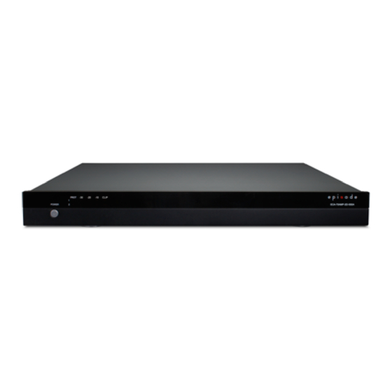
Page 4: Front Panel
Speaker Output Connections equipment to be controlled from the same 12 volt Set-screw connections for speaker output signal. channels 1 & 2. Accommodates 22-12AWG 10. AC Fuse wire. Replaceable main power fuse. ©2014 Episode™ Pg. 7 Pg. 6 ©2014 Episode™... -
Page 5: Positioning The Amplifier
10.1. Terminating Wire in Set-Screw Connectors Episode amplifiers are designed to help deliver a great audio experience that makes your music come alive for years to come. However, where you place the amplifier can have a large effect on the performance that you Strip the outer jacket of the cable (if applicable) back about 2”, and then strip the insulation of each wire... -
Page 6: Amplifier Power Control
When a source attached to any input generates a signal, the amplifier will power on, and will remain on as long as the signal is maintained. After 20 minutes of inactivity on all inputs, the amplifier will power down and return to Stand-by mode until a signal is received again. ©2014 Episode™ Pg. 11 Pg. 10... -
Page 7: Application Diagram
AUTO T4AL 250V E330247 POWER MODE 19.00in. LOOP OUT option for use with PROT CLIP 1.75in. 2.30in. POWER ECA-70AMP-2D-300A another amp. LOOP OUT option 17.40in. 11.00in. for use with another amp. 19.00in. ©2014 Episode™ Pg. 13 Pg. 12 ©2014 Episode™... -
Page 8: Troubleshooting
Products to be repaired under this warranty must be returned to SnapAV or a designated service center with prior notification and an assigned return authorization number (RA). ©2014 Episode™ Pg. 15 Pg. 14... - Page 9 Rev: 140417-1430 Pg. 16 ©2014 Episode™...
Need help?
Do you have a question about the ECA-70AMP-2D-150A and is the answer not in the manual?
Questions and answers