Table of Contents
Advertisement
PROT -30
-20
-10
CLIP
1
2
CH1
ETHERNET
IN
IR RS232
DRY
CONTACT
OUT
S
G G
TxRx In1 In2
CH2
12V TRIGGER
LOOP
UNBALANCED
OUT
BALANCED INPUTS
SPEAKER OUT
_ _
_
_
CH3 CH4
CH1 CH2
+
+
+
+
G
G
CH1
CH2
LEVEL
INPUTS
INSTALLATION MANUAL
ESA-70V2CH-150W
ESA-70V2CH-300W
ESA-70V2CH-500W
CAUTION:
ATTENTION:
R
FOR CONTINUED PROTECTION AGAINST
UTILISER UN FUSIBLE DE RECHANGE
RISK OF FIRE, REPLACE ONLY WITH
D E M E M E T Y P E E T C A L I B R E .
SAM
E
TYPE FUSE
AND RATING.
ECA-70IPAMP-2D-150
100/120V~60Hz 3.15A
T3.15A L 250V
220/240V~50Hz 1.6A
T1.6A L 250V
Advertisement
Table of Contents

Summary of Contents for Episode ESA-70V2CH-150W
- Page 1 INSTALLATION MANUAL ESA-70V2CH-150W ESA-70V2CH-300W ESA-70V2CH-500W PROT -30 CLIP ECA-70IPAMP-2D-150 BALANCED INPUTS SPEAKER OUT ETHERNET IR RS232 CH3 CH4 CH1 CH2 CONTACT TxRx In1 In2 100/120V~60Hz 3.15A 12V TRIGGER LOOP UNBALANCED LEVEL CAUTION: ATTENTION: T3.15A L 250V FOR CONTINUED PROTECTION AGAINST UTILISER UN FUSIBLE DE RECHANGE 220/240V~50Hz 1.6A...
-
Page 2: Important Safety Instructions
page | 2 CAUTION Risk of Electrical Shock! DO NOT OPEN! ATTENTION ! RISQUE DE CHOC ! ÉLECTRIQUE PAS OUVRIR ! The lightning flash with arrowhead symbol, within an equilateral triangle, is intended to alert the user to the presence of uninsulated dangerous voltage within the product’s enclosure that may be of sufficient magnitude to constitute a risk of electric shock to persons. -
Page 3: Consignes De Sécurité Importantes
17. LA PRISE PRINCIPALE DU CORDON D’ALIMENTATION doit rester facilement accessible . 18. ATTENTION: POUR RÉDUIRE LE RISQUE DE CHOC ÉLECTRIQUE, NE PAS RETIRER. NO réparable par l’utilisateur pièces à l’intérieur. CONFIER L’ENTRETIEN DE PERSONNEL QUALIFIÉ . © 2016 Episode®... -
Page 4: Speaker Recommendation
| 4 INTRODUCTION Thank you for purchasing Episode® amplifiers. To complete installation, follow these instructions. Visit our website for design recommendations and speaker calculators. The ESA-70V2CH 2-channel, 70-volt digital power amplifier series is designed for applications requiring two channel stereo audio, or two mono zones of audio with different sources or levels. -
Page 5: Front Panel
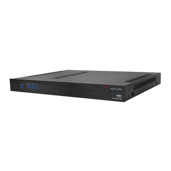
| 5 FRONT PANEL ESA-70V2CH-150W, 300W PROT -30 CLIP ESA-70V2CH-IP-150W ESA-70V2CH-500W PROT -30 CLIP ESA-70V2CH-IP-500W A. Power Switch with LED Indicator Momentary switch for manual control of standby power mode. BLUE – On. RED – Standby. B. Protection LED Indicates whether a channel is operating correctly or is in protection. -
Page 6: Rear Panel
| 6 REAR PANEL ESA-70V2CH-150W, 300W BALANCED INPUTS SPEAKER OUT ETHERNET IR RS232 CH3 CH4 CONTACT TxRx In1 In2 VOLTAGE SWITCH ON BOTTOM 12V TRIGGER LOOP UNBALANCED LEVEL CAUTION: ATTENTION: 100/120V~60Hz 3.15A T3.15A L 250V FOR CONTINUED PROTECTION AGAINST... -
Page 7: Bottom Panel
230V AC. See the Specifications on page14 for the correct fuse type for each model. Using the wrong fuse could result in blown fuses or damage to the amplifier, which is not covered by the warranty. © 2016 Episode®... -
Page 8: Positioning The Amplifier
page | 8 POSITIONING THE AMPLIFIER Placing the amplifier can have a large impact on performance and longevity. Please take the following guidelines into consideration. Shelf Mounting • Be sure that the unit is in a well-ventilated area that provides adequate cooling. •... -
Page 9: Rack Mounting
2" of depth behind unit to accommodate cables and Minimum of 1.75" of free air connectors space above and below Minimum of 1.75" of free air space above and below Minimum of 3" free air space on each side © 2016 Episode®... -
Page 10: Source Connections
page | 10 SOURCE CONNECTIONS Balanced Input Use the BALANCED INPUT to connect balanced or unbalanced cables to the amplifier. Positive(+) Positive(+) Shield Shield CH 1 CH 1 Negative(-) Negative(-) Negative(-) Negative(-) Ch 2 Shield Ch 2 Shield Positive(+) Positive(+) Note jumper between Shield and Negative(-). -
Page 11: Speaker Connections
Username: admin • Password: admin The following settings can be changed in the web GUI: • System Status • Power On settings • Input/Output configuration • Network IP and Clock settings • Audio Routing configuration • Password settings © 2016 Episode®... -
Page 12: Amplifier Power Control
page | 12 AMPLIFIER POWER CONTROL Front Panel Power Button When the amplifier is powered ON, the power button will illuminate solid blue. When it is in STAND-BY, the power button will be red. Resetting the Amplifier Press and hold the power button for 10 seconds once the receiver is powered on for a “soft” reset. -
Page 13: Application Diagram
Connect a subwoofer or subamp using the LOOP OUT port on the amplifier and the LFE port on the Subwoofer or Subamp. Two Sources with Two Mono Output Zones ESA-70V2CH-150W, 300W Source 2 (Unbalanced Input) Source 1 (Unbalanced RCA) From Automation System... -
Page 14: Volume Calibration
page | 14 Volume Calibration To calibrate source input volume and inline volume control level: Connect all speaker and audio source wiring. Connect power to the amplifier. (If applicable) Set all volume controls to their maximum volume setting. Set each input level knob to 50% and set the input level for unused channels to minimum. -
Page 15: Specifications
17"W x 3.49"H x 15”D Weight 7.8 lbs 13.56 lbs 18.00 lbs Certification Meets FCC Part 15, UL EN60065 DIMENSIONS 3.49in 3.86in PROT -30 CLIP ESA-70V2CH-500W 15.00in. 17.00in. 19.00in. PROT -30 CLIP 1.73in. 2.10in. ECA-70IPAMP-2D-150 17.00in. 14.00in. 19.00in. © 2016 Episode®... -
Page 16: Troubleshooting
WARRANTY 2-Year Limited Warranty Episode® Amplifiers have a 2-Year Limited Warranty. This warranty includes parts and labor repairs on all components found to be defective in material or workmanship under normal conditions of use. This warranty shall not apply to products that have been abused, modified or disassembled.


Need help?
Do you have a question about the ESA-70V2CH-150W and is the answer not in the manual?
Questions and answers