Wolf OG36-LP Technical & Service Manual
Outdoor grill og series
Hide thumbs
Also See for OG36-LP:
- Installation manual (56 pages) ,
- Use and care manual (44 pages) ,
- Installation manual (18 pages)

Related Manuals for Wolf OG36-LP


Summary of Contents for Wolf OG36-LP
- Page 1 Technical Service Manual Outdoor Grill (OG) Series © WOLF APPLIANCE, INC. 2009 ALL RIGHTS RESERVED JOB AID #814144 Revision A - July, 2009...
-
Page 3: Section 1 - General Information
General Information Outdoor Grill (OG) Series SECTION 1 GENERAL INFORMATION #814144 - Revision A - July, 2009... -
Page 4: Introduction
Wolf appliance units by anyone other than Authorized Service Technicians. The information and images contained in this manual are the copyright property of Wolf appliance, Inc. Neither this manual nor any information or images contained herein may be copied or used in whole or in part without the express written consent of Wolf Appliance, Inc.©, all rights reserved. -
Page 5: Table Of Contents
General Information Outdoor Grill (OG) Series TABLE OF CONTENTS Page # Page # Section 1 - General Information ........1-1 Section 3 -Theory of Operation ........3-1 Introduction................. 1-2 Operation Information ............3-2 Important Safety Information..........1-2 Types of Fuel Gases ............. 3-2 Technical Assistance............ -
Page 6: Warranty Information
Outdoor Grill (OG) Series WARRANTY INFORMATION This page contains a copy of the One (1) Year Outdoor Warranty supplied with every Wolf OG Series unit. On the following page is the serial number information, which is needed for warranty purposes. -
Page 7: Model Number Key
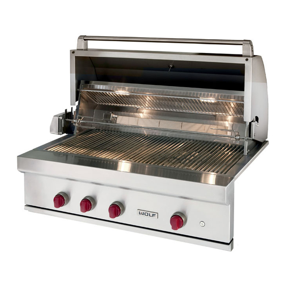
A model/serial tag is attached to the bottom flange of the grill’s front panel. This tag contains only the model num- ber, manufacturer number and serial number (See Figures 1-1 & 1-3). The rating plate/serial tag is located behind the front panel, above the drip tray. It contains gas and electrical OG36-LP 0910 11360000 M O D E L : Mfg. - Page 8 Model OG30 MODEL DESCRIPTION OG36 Outdoor Grill, 36 inches wide, Natural Gas OG36-LP Outdoor Grill, 36 inches wide, LP Gas Burner Composition & Specifications: • Two 25,000 btu/hr Grill Burners • One 25,000 btu/hr Infrared Sear Burner • One 14,000 btu/hr Rotisserie Burner...
- Page 9 • Heavy-duty classic stainless steel construction. • Hood front is double lined for better insulation. • Wolf signature red control knobs—optional black • Two halogen interior lights illuminate grilling surface. knobs available. • LED lit control knobs allow for convenient night •...
- Page 10 General Information Outdoor Grill (OG) Series OUTDOOR GRILL CART MODELS AND DESCRIPTIONS MODEL DESCRIPTION CART30 CART for 30 inches wide OG Door / Drawer Composition: • Two Doors • Zero Drawers CART30 MODEL DESCRIPTION CART36 CART for 36 inches wide OG Door / Drawer Composition: •...
- Page 11 General Information Outdoor Grill (OG) Series OUTDOOR GRILL CART FEATURES • Grill carts fit 30" (762), 36" (914) and 42" (1067) wide outdoor grills. • Heavy-duty classic stainless steel construction. • Fold-down side shelves with tool holders on left shelf. •...
- Page 12 General Information Outdoor Grill (OG) Series 1-10 #814144 - Revision A - July, 2009...
-
Page 13: Section 2 - Installation Information
Installation Information Outdoor Grill (OG) Series SECTION 2 INSTALLATION INFORMATION #814144 - Revision A - July, 2009... -
Page 14: General Installation Information
The proper voltage, frequency, and amperage rat- Wolf portable grill carts are available to fit all Wolf out- ings are listed on the product rating plate. door grill models (see next page). -
Page 15: Og And Cart Overall Dimensions
Installation Information Outdoor Grill (OG) Series OG and OG Cart Overall Dimensions OUTDOOR GRILL (Model OG36 shown) 30" (762) OVERALL DEPTH 27" (686) OVERALL HEIGHT " " (318) (64) TO GRILLING CLEARANCE SURFACE FOR OPEN HOOD " (705) OVERALL WIDTH GRILL CART (Model CART36 shown) 12"... -
Page 16: Built-In Applications
If the grill is to be placed into combustible enclosure, an approved insulating liner is necessary to prevent fire, prop- erty damage and bodily injury. Use only the Wolf insulating liner. See Figure 2-1 below and refer to the illustration on the next page for an OG model. -
Page 17: Og Built-In Installation Dimensions
Installation Information Outdoor Grill (OG) Series OG Built-in Installation Dimensions COMBUSTIBLE ENCLOSURE NON-COMBUSTIBLE ENCLOSURE (With Insulating Liner) " " (19) (19) OPENING OPENING FOR LINER FOR GRILL COUNTERTOP COUNTERTOP OVERHANG OVERHANG 12" (305) min TO " (64) min TO COMBUSTIBLE REAR SURFACES NON-COMBUSTIBLE REAR SURFACES 26"... -
Page 18: Electrical Requirements
Conversion kits are available for both LP and natural dry location, away from the grill firebox and excessive gas grills. Contact a Wolf dealer or distributor for more heat area, but within 2' (.6 m) of the right rear grill open- information. -
Page 19: Natural Gas Installations
If the gas grill is not in use, the gas fied by Wolf. Use only gas piping that is approved for must be turned off at the LP gas cylinder. If the grill is use with natural and LP gases. -
Page 20: Lp Gas Installations (Portable Lp Connection)
LP Gas Installation (Portable LP Connection) LP Gas Connection One of the features of a Wolf OG grill cart is the pull-out Install the pressure regulator and hose assembly sup- shelf for easy access to the LP gas cylinder. It is... -
Page 21: Gas Leak Testing
GAS LEAK TESTING OUTDOOR GRILL ASSEMBLY NOTE: Never use the outdoor grill without first testing Except for some minor parts, Wolf outdoor grills are the gas line connections for gas leaks. produced fully assembled and tested in the factory and require no major assembly in the field. -
Page 22: Installing Grill To Cart
Install Grill to Cart There is a Wolf portable grill cart available to fit each Wolf outdoor grill model. To install a grill on a cart: 1. Attach casters to bottom corners of cart (locking casters in front) using the nuts supplied with the casters. -
Page 23: Section 3 -Theory Of Operation
Theory of Operation Outdoor Grill (OG) Series SECTION 3 THEORY OF OPERATION #814144 - Revision A - July, 2009... -
Page 24: Operation Information
Theory of Operation Outdoor Grill (OG) Series OPERATION INFORMATION A service technician should understand how a gas appliance operates before attempting to service the appliance. This section provides brief descriptions of some of the more common types of fuel gases and explains gas heating values. -
Page 25: Principals Of Gas Combustion
Theory of Operation Outdoor Grill (OG) Series PRINCIPLES OF GAS COMBUSTION Combustion - The process of burning. Requirements for Combustion - There are three required elements for combustion to occur; Fuel (Gas), Oxygen (Air) and Heat (Ignition Temperature, which for gas is between 1100°F/593°C and 1200°F/649°C). All must be pres- ent. -
Page 26: Types Of Burners
Theory of Operation Outdoor Grill (OG) Series Types of Burners Burner Body with Burner Ports Blue Flame Burners - The U-shaped burners in the Outdoor Grill are blue flame burners (See Figure 3-1). With this type of burner, primary air is mixed with the fuel gas before the gas reaches the burner ports. -
Page 27: Simple Theory Of Operation
Theory of Operation Outdoor Grill (OG) Series Simple Theory of Operation: Gas arrives at the appliance through pipes in the form of natural gas or liquid propane gas. This gas supply can be from a local utility source or a tank source. - Page 28 Theory of Operation Outdoor Grill (OG) Series Burner Body The gas and air travel through the venturi Valve tube and the mixing tube where the gas and air mix together. The gas and air mixture then enters into the burner body. (See Figure 3-6) Shutter Venturi...
-
Page 29: Section 4 - Component Access And Removal
Component Access / Removal Outdoor Grill (OG) Series SECTION 4 COMPONENT ACCESS AND REMOVAL #814144 - Revision A - july, 2009... -
Page 30: Warnings And Cautions
Component Access / Removal Outdoor Grill (OG) Series COMPONENT ACCESS AND REMOVAL This section explains how to access and remove components. Since there are only slight variations between each of the OG models, diagrams of the model OG42 are used in most cases. An attempt has been made to arrange these procedures in such a way as to simulate which components would need to be removed first in order to gain access to other components. -
Page 31: Halogen Lamp
Component Access / Removal Outdoor Grill (OG) Series Drip Pan Assembly The drip pan assembly rides on rollers at the front bot- tom of the grill chassis, with two rollers attached to the rear of the pan fitting in channels on each side of the grill chassis. -
Page 32: Handle And Endcaps
Component Access / Removal Outdoor Grill (OG) Series Handle and Endcaps Set-Screw Standoff A socket head set-screw inserted through the bottom of each standoff holds the handle in the standoffs. The standoffs are then attached to the hood with screws Standoff passing through the hood into the back of the standoffs. -
Page 33: Burner Flash Tubes
Component Access / Removal Outdoor Grill (OG) Series Burner Flash Tubes Burner flash tubes are attached to the inside front of the Flash Tube burner box with screws. To remove a flash tube, first remove the grates and bri- quette trays above the flash tune, then use a Phillips- head screwdriver to extract the flash tube mounting screws and pull the flash tube from the burner box. -
Page 34: Control Knob Bezels
Component Access / Removal Outdoor Grill (OG) Series Control Knob Bezel Control knob bezels are attached to the front panel with screws. To remove a control knob bezel, first remove the control knob in front of it, then extract the bezel mounting screws and pull the bezel from the front panel. -
Page 35: Lights Power Switch
Component Access / Removal Outdoor Grill (OG) Series Lights Power Switch The body of the lights power switch passes through a hole in the front panel, with a nut on the back side threaded onto the body of the switch holding it in place. To remove the switch, first detach the front panel from the landing ledge as described in steps 1 and 2 of Front Panel Assembly removal instructions, then (See Figure... -
Page 36: Gas Burner Orifice
Component Access / Removal Outdoor Grill (OG) Series Gas Burner Orifice A gas burner orifice is threaded onto each burner valve (except the rotisserie burner valve), opposite the burner Orifice knob shaft. To remove an orifice, first remove the grates, briquette tray(s) and corresponding burner. -
Page 37: Gas Regulator (Natural Gas - Convertible)
Component Access / Removal Outdoor Grill (OG) Series Gas Regulator (Natural Gas - Convertible) The gas regulator is attached to the end of the manifold pipe, between the manifold and the gas supply line. NOTE: The directions below were written with the assumption that the grill is sitting on a cart and/or there is access to the manifold from the bottom front or bot- Gas Supply... -
Page 38: Hood Assembly And/Or Hood Springs
Component Access / Removal Outdoor Grill (OG) Series Hood Assembly and/or Hood Springs Hood Assembly The ends of the hood springs are hooked over studs, one attached to each side of the rear hood assembly Bolt and protruding out; one attached to each side of the hood assembly and protruding in. -
Page 39: Rotisserie Burner Orifice
Component Access / Removal Outdoor Grill (OG) Series Rotisserie Burner Orifice The rotisserie burner orifice is threaded into the end of the rotisserie burner orifice elbow. To remove the orifice, first remove the rear hood shell, then use a 13 mm wrench or crescent wrench to remove the orifice from the orifice elbow while holding the elbow with another wrench. -
Page 40: Rotisserie Burner Igniter
Component Access / Removal Outdoor Grill (OG) Series Rotisserie Burner Igniter The rotisserie burner igniter is attached to the side of the igniter bracket with a bolt and nut. The bracket is attached to the rear hood assembly with two screws. The igniter wire leads run out the back of the rear hood assembly and down through a hole in the rear deck of Igniter Wires... -
Page 41: Halogen Lamp Assembly (Light Socket)
Component Access / Removal Outdoor Grill (OG) Series Halogen Lamp Assembly (Light Socket) Lamp Assembly The halogen lamp assemblies are attached to the rear hood assembly with retaining tabs and a screw. The light socket wire leads are routed down through a hole in the rear deck of the burner box and tied into a wire harness attached to the rear flange of the burner box. - Page 42 Component Access / Removal Outdoor Grill (OG) Series 4-14 #814144 - Revision A - July, 2009...
- Page 43 Troubleshooting Outdoor Grill (OG) Series SECTION 5 TROUBLESHOOTING #814144 - Revision A - July, 2009...
-
Page 44: Troubleshooting Guide Table Of Contents
Troubleshooting Outdoor Grill (OG) Series TROUBLESHOOTING GUIDE TABLE OF CONTENTS The Troubleshooting Guide Table of Contents indicates how the Troubleshooting Guide is arranged. To use the Troubleshooting Guide: 1. Match the description of the problem the unit is experiencing with those in the table of contents. 2. -
Page 45: No Ignition At All Burners
Troubleshooting Outdoor Grill (OG) Series PROBLEM POSSIBLE CAUSE TEST / ACTION A. No Ignition at All Burners Insufficient Ignition Attempt Control knob must be pushed in and held for minimum of 2 - 3 seconds before turning control knob in order to energize glow igniter. Instruct customer. -
Page 46: Flame Is Yellow, Possibly With Gas Odor Present
Troubleshooting Outdoor Grill (OG) Series PROBLEM POSSIBLE CAUSE TEST / ACTION D. Flame is Yellow, Possibly Poor Gas and Air Mixture 1. Check around burner shutter for obstruction with Gas Odor Present (EX: spider webs, insects, etc.); Remove obstruction. 2. Check the air shutter for proper adjustment; adjust as needed. -
Page 47: Hood Discoloration
Troubleshooting Outdoor Grill (OG) Series PROBLEM POSSIBLE CAUSE TEST / ACTION L. Hood Discoloration Some Discoloration is Normal Instruct customer. Excessive Burn-off Time Period Burn-off should not exceed fifteen (15) minutes. M. Interior Light(s) Inoperative Bulb Burned Out If one bulb is energized, but not the other, replace defective bulb. -
Page 48: Thermometer Is Not Reaching High Temperatures
Troubleshooting Outdoor Grill (OG) Series PROBLEM POSSIBLE CAUSE TEST / ACTION O. Thermometer is not reaching Insufficient Time with Hood Closed Allow grill at least fifteen (15) minutes with hood high temperatures closed at high setting in order to reach higher temperatures. -
Page 49: Section 6 - Technical Data
Technical Data Outdoor Grill (OG) Series SECTION 6 TECHNICAL DATA #814144 - Revision A - July, 2009... -
Page 50: Technical Data Table
Technical Data Outdoor Grill (OG) Series TECHNICAL DATA TABLE Gas Supply Line Pressure Natural Gas and Liquid Propane Maximum 14” WC Natural Gas Minimum 7” WC Liquid Propane Minimum 11” WC Gas Manifold Pressure Natural Gas with Standard Orifice 4” WC Liquid Propane Gas with Standard Orifice 10”... - Page 51 Wire Diagrams Outdoor Grill (OG) Series SECTION 7 WIRE DIAGRAMS #814144 - Revision A - July, 2009...
- Page 52 Wire Diagrams Outdoor Grill (OG) Series WIRE DIAGRAMS - OUTDOOR GRILLS -This wiring information is provided for use by qualified service personnel only. 12 VAC 12 VAC -Disconnect appliance from electrical supply before beginning service. -Be sure all grounding devices are connected when service is complete. HALOGEN HALOGEN -Failure to observe the above warnings may result in severe electrical shock.
Need help?
Do you have a question about the OG36-LP and is the answer not in the manual?
Questions and answers