Table of Contents
Advertisement
Quick Links
Advertisement
Table of Contents

Related Manuals for Novatel DL


Summary of Contents for Novatel DL
- Page 1 User Manual...
-
Page 2: User Manual
Information in this document is subject to change without notice and does not represent a commitment on the part of NovAtel Inc. The software described in this document is furnished under a license agreement or non-disclosure agreement. The software may be used or copied only in accordance with the terms of the agreement. It is against the law to copy the software on any medium except as specifically allowed in the license or non-disclosure agreement. -
Page 3: Table Of Contents
Power Port & Cable .................................22 Using the Removable Flash Memory Card.......................23 Sleep, Power Down and the Power Switch.......................25 Status Indicators ...............................26 3 - USING THE DL System Behavior ..............................27 Self-Test...................................27 Autonomous Versus Host Controlled Operation ......................27 Default Schedule and Group Configuration ........................27 Site Records in Scheduled (Automatic) Logging Sessions....................27... - Page 4 Table of Contents APPENDICES APPENDIX A - DL DRAWINGS APPENDIX B - DL SPECIFICATIONS APPENDIX C - PC CARD SPECIFICATIONS APPENDIX D - PORT & CABLE PINOUTS APPENDIX E - DL COMMANDS Battery ..................................48 Del ....................................48 Dir ....................................49 Dump..................................49 Group..................................50 Loggroup ..................................53...
- Page 5 APPENDIX I - OPTIONAL MOUNTING BRACKET APPENDIX J - COMMAND PROMPT INTERFACE TABLES 1: Positioning Modes of Operation.............................12 2: Feature Summary - DL Models............................13 3: Allowable Antenna Types..............................17 4: Status Indicators - Meaning ............................26 5: Auto-Generated File Name Convention.........................30 6: Storage Requirements per Data Record .........................30 7: Memory Consumption –...
- Page 6 Table of Contents FIGURES 1: NovAtel DL – Front & Rear ............................11 2: Typical DL Configuration – Office..........................15 3: Typical DL Configuration – Field..........................16 4: Close-up of Ports on Rear End-cap ..........................19 5: Removing a Connector..............................19 6: Opening the Cover .................................24 7: Handling the PC Card ..............................24...
-
Page 7: Warranty Policy
NovAtel Inc. You must obtain a RETURN MATERIAL AUTHORIZATION (RMA) number by contacting Customer Service in any of the ways described on the next page. This number is needed before shipping any product to NovAtel or your Dealer. -
Page 8: Customer Service
Customer Service CUSTOMER SERVICE For customer support contact your local NovAtel dealer first. If the problem remains unresolved, contact NovAtel directly by any of the following ways: • toll-free hotline: 1 800 NOVATEL (8:00 AM - 4:30 PM MST, Canada and U.S.A. only) •... -
Page 9: Notice
Do not eject the PC Card while the DL is logging data, as you may lose part of or your entire data file. The DL can accept an input supply voltage in the range +10.7 to +18 V DC. This may not be the same range as other NovAtel products with which you are familiar. -
Page 10: Foreword
The following may provide you with additional valuable reference information: • SoftSurv User Manual - a description of the SoftSurv suite of GPS surveying programs and utilities. SoftSurv and DL are complementary products designed to work together. SoftSurv software provides a user-friendly graphical interface to the DL, allowing you to focus on your work without needing to learn about the MiLLennium’s commands and logs. -
Page 11: Overview
Depending on which model you purchase, it is capable of receiving and tracking the L1 C/A-code, L1 and L2 carrier phase, and L2 P-code (or encrypted Y-code) of up to 12 GPS satellites. The DL can be used for either single-point or differential applications. -
Page 12: Models & Features
1 – Overview MODELS & FEATURES Table 1 lists the four available DL models available, each capable of multiple positioning modes of operation: Table 1: Positioning Modes of Operation Positioning Modes of Operation DL Model DL-L1 DL-RT20S DL-L2 DL-RT2 √... -
Page 13: Operating Modes
• Manual Operation: Among other things, a host computer can transmit scheduling and logging parameters, receive collected data, and turn the DL on or off. In this mode, the DL does not need to be tracking satellites, or even have an antenna connected to it. -
Page 14: Accessories And Options
The NovAtel DL can be used with the following accessories: • SoftSurv software – a suite of programs that allows you to plan your data collection trip, configure your DL or handheld data logger, post-process your collected data, and archive your information sets •... -
Page 15: Set Up
SETTING UP AT THE OFFICE Figure 2 displays how you might typically set up the DL at the office – for example, to load a schedule, or to transfer collected data to a PC. In this situation, the PC is connected to the COM1 port, and energy is supplied by means of an AC/DC converter that is connected to the Power port. -
Page 16: Setting Up In The Field
Mount or place the DL on a secure, stable structure that will not sway or topple. For example, attach the DL to a tripod leg using the optional mounting bracket (see Figure 14: Mounting Bracket and Figure 15, Appendix I). -
Page 17: Choose The Right Antenna
Insert a PC Card into the DL (see Using the Removable Flash Memory Card, Page 23). Connect the output of a power source (e.g. battery) to the input power port of the DL (see Power Port & Cable, Page 22). Once power is supplied, the DL turns on automatically, begins an initialization sequence, and then enters low- power mode. - Page 18 WARNING: While there may be other antennas on the market that might also serve the purpose, please note that the performance specifications of the DL are guaranteed only when it is used with a NovAtel model 531 (L1) or model 502 (L1/L2) GPSAntenna.
-
Page 19: Connect Cables
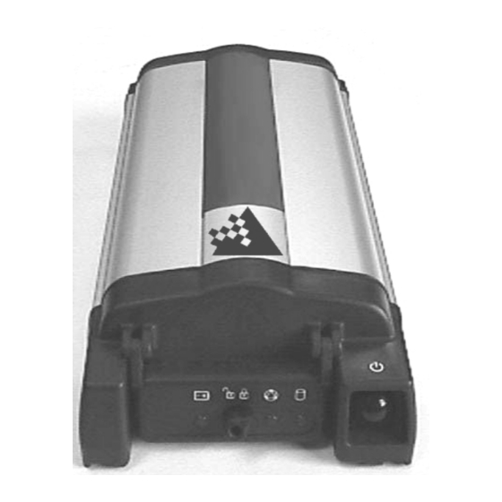
Figure 4: Close-up of Ports on Rear End-cap Each connector is keyed to ensure that the cable can be inserted in only one way, to prevent damage to both the DL and the cables. Furthermore, the connectors that are used to mate the cables to the DL have a locking mechanism that requires careful insertion and removal. -
Page 20: Serial Ports & Cables
For example, you could connect the DL to an aerial camera in such a way that the DL recorded its position whenever the shutter button was pressed. This port is not typically used for stand-alone applications. -
Page 21: Peripheral Power Supply Via Com2 Port
Good-quality cable introduces lower losses than low-quality cable. If the cable loss becomes too great, excessive signal degradation occurs and the DL may be unable to meet its performance specifications. -
Page 22: Power Port & Cable
(if available) without any interruption in its logging activities. Consider the case where the DL is connected to two 12 V DC batteries. As described in Table 4, Page 26, as the voltage drops on the first battery, the Power indicator color changes from green to amber, then to red. Warning messages are sent on the serial port indicating that battery power is becoming exhausted (see the description of the LPSTATUSA log, Page 73 and MSGA log, Page 75 if you require further information). -
Page 23: Using The Removable Flash Memory Card
Improper selection of wire gauge can lead to an unacceptable voltage drop at the DL. A paired wire run represents a feed and return line; therefore, a 2-m wire pair represents a total wire path of 4 m. For a DL operating from a 12 V DC battery system, a power cable longer than 2.1 m (7 ft) should not use a wire diameter smaller than that of 24... -
Page 24: Opening The Cover
In this case, do not force the card! Remove it, orient it properly, and then insert it. After the card is locked in place, close the cover again. Figure 7: Handling the PC Card DL™ User Manual Rev 3... -
Page 25: Sleep, Power Down And The Power Switch
DL monitors its serial ports, and becomes fully operational a short while after as serial port activity is detected – for example, if a key is pressed on a handheld data logger that is plugged into one of the DL’s serial ports. The time required to wake up is only a few seconds, but it may require an additional few minutes to initialize the GPS receiver and allow it to establish an initial time and position. -
Page 26: Status Indicators
Power off or PC Card not detected, or initialized. When the DL is connected to an AC/DC converter, the Power indicator may be ignored as long as the color is green; if it turns red, then you should investigate whether there is a problem with either the AC supply or the converter itself. -
Page 27: Using The Dl
3 – Using the DL 3 - USING THE DL Before using the DL for the first time, ensure that you have followed the installation instructions of Chapter 2 - Set Up, Page 15. See CAUTION!, Page 9, for a list of items of which you should be aware as you use the DL. -
Page 28: Communications With The Dl
DL records raw data in the form of logs, which are written to the data file on a periodic basis. NovAtel’s SoftSurv post- processor automatically interprets these logs and the data that they contain. If you wanted to analyze the data in these logs yourself, the details of the logs are documented in Appendix F - DL Logs, Page 64 of this manual. -
Page 29: Schedule Logging Operation
You can only provide a file name when you are scheduling a single data collection event. If you are scheduling a series of events, you have to accept the DL’s auto-generated names. An acceptable file name consists of a base of up to eight characters, followed by a .PDC extension. -
Page 30: Data Storage Requirements
Session ID assigned in sequence (0 .. 9, A .. Z) based on the presence of files previously logged on a particular day. For example, a DL might have a serial number such as CGN95450087. A date such as January 25 has an UTC day-of- year representation of 025. The 15 schedule of the day would have an entry index of E. -
Page 31: Errors
3 – Using the DL Table 7: Memory Consumption – Typical Case for RTK Survey (2 Second Rate) L1-only L1 & L2 Single-point Single-point or Differential Single-point Single-point or Differential Observations Observations & Positions Observations Observations & Positions (kBytes/hour) (kBytes/hour) -
Page 32: Firmware Upgrades & Updates
This can be done anytime, anywhere, without any mechanical procedures whatsoever. New firmware can be transferred to the DL through a serial port, immediately making the unit ready for operation at a higher level of performance. This also prevents rapid obsolescence. -
Page 33: Updating Using The "Loader" Utility
You must first acquire the latest firmware revision, which comes as a file with a name such as OEMXYZ.EXE (where XYZ is the firmware revision level). This file is available from NovAtel’s FTP site (ftp.novatel.ca), or via e-mail (support@novatel.ca). Alternately, the file can be mailed to you on floppy disk. -
Page 34: Loader Options
At the prompt, enter your update auth-code (e.g. 17b2,32df,6ba0,92b5,e5b9,millenrt2). When prompted by the program, turn on the DL. Loader automatically establishes communications with the DL. The time required to transfer the new program data depends on the bit rate which was selected earlier. -
Page 35: Upgrade Or Update The Pdc Card
Ensure your PC and DL are properly connected, see Setting Up At The Office, Page 15. The serial data cable should go from any COM port on the PC to COM2 on the DL. Have all power cables in place but do not turn on the DL just yet. -
Page 36: Appendix A - Dl Drawings
Appendix A – DL Drawings APPENDIX A - DL DRAWINGS Figure 10: Views 117.45 SECTION 82.1 130.0 252.2 All dimensions are expressed as millimeters. DL™ User Manual Rev 3... -
Page 37: Appendix B - Dl Specifications
POWER MANAGEMENT If the DL is connected to two batteries, it begins using the one with the higher voltage across its terminals. When this voltage drops to 10.7 V DC, the Power indicator color changes from green to amber. When the voltage drops below 10.0 V DC, the battery is unusable;... - Page 38 When the DL is turned on, this clock is initialized using the GPS time reference, and will indefinitely maintain an accuracy of +1 second and a resolution of 1 second. When the DL is turned off, the clock begins to drift. To compensate for this drift, the DL emerges from sleep mode in advance of the next scheduled data-collection session in order to re-initialize itself.
- Page 39 Appendix B – DL Specifications PERFORMANCE (Subject To GPS System Characteristics) RT-2 Pseudorange & carrier-phase double differencing (fixed < 2 cm RMS accuracies with RTK carrier-phase positioning). Conditions: <10 km baseline length; ≥ 6 satellites at an elevation > 12°; after 2 minutes convergence; with choke-ring ground plane at base station.
-
Page 40: Appendix C - Pc Card Specifications
PC CARD SOCKET The socket on the DL accommodates one Type II or Type III PC Card. The socket specification conforms to the PC Card Standard release 2.1+, except that 12 V operation and programming is not supported. Only 3.3 V and 5 V operation and programming are supported. -
Page 41: Appendix D - Port & Cable Pinouts
POWER POWER CONNECTOR The power connector on the DL is a LEMO HGM.0B.304.CLAP, with the pins assigned as shown in the following table. The two possible independent power sources are designated A and B: Table 9: Power Connector Pin Assignment... -
Page 42: Com2 Serial Port - Connector Pin Assignment
SERIAL PORT CONNECTORS The two serial ports (COM1 and COM2) on the DL use LEMO EEG.IK.310.CLN sockets, with the pins assigned as given in Table 10: COM2 Serial Port - Connector Pin Assignment and Table 11: COM1 Serial Port - Connector Pin... -
Page 43: Straight Serial Cable - Pin Assignment
Pin 4 Orange Pin 4 Pin 5 Yellow Pin 5 Pin 6 Green Pin 6 Pin 7 Blue Pin 7 Pin 8 Violet Pin 8 Pin 9 NULL Grey Pin 9 Pin 10 White (Not used) DL™ User Manual Rev 3... -
Page 44: Null-Modem Cable - Pin Assignment
Yellow Pin 5 Pin 6 Green Pin 4 Pin 7 Blue Pin 8 Pin 8 Violet Pin 7 Pin 9 NULL Grey Pin 9 Pin 10 White (Not used) Pin 1 jumpered to Pin 6 DL™ User Manual Rev 3... -
Page 45: I/O Connector Pin Assignment
Appendix D – Port & Cable Pinouts INPUT / OUTPUT I/O CONNECTOR The input/output (I/O) port on the DL uses a LEMO EEG.1K.308.CLN double-keyed socket, with the pins assigned as given in the following table: Table 14: I/O Connector Pin Assignment... -
Page 46: I/O Cable – Pin Assignment
MKI, mark input Orange Pin 5 STATUS , valid solutions available Yellow Pin 6 Green Pin 7 Blue Pin 8 White Y CABLE Reference Description Brown (-ve) Orange (+ve) (+ve) Black (-ve) Female LEMO Plug DL™ User Manual Rev 3... -
Page 47: Appendix E - Dl Commands
Write data to a specified file on the PC Card The arguments to each of these commands are described in the following sections. For a complete listing and description of the other commands that the DL is capable of processing, please consult the MiLLennium GPSCard Command Descriptions Manual. -
Page 48: Battery
This command allows you to select the power source for the system and display battery status. For example, you can override the DL’s method of selecting the active battery, when two batteries are connected. To do this the desired battery identifier (A or B) must be specified in the command. -
Page 49: Dir
Appendix E – DL Commands This command either displays a list of stored files on the PC Card, or the file header information for the specified log file. It also displays additional group information when it has been supplied as part of a group definition. -
Page 50: Group
Up to ten groups can be defined. The group name can be up to nine characters in length. If a group named “POWERUP” is defined, this group’s log specification is executed when the DL determines what time it is, after the DL is turned on. - Page 51 Appendix E – DL Commands GROUP ADD groupname [arguments & data] Command Option Description Default GROUP ADD Command groupname group name The name of a group (e.g. “alpha”) which is either being created or modified arguments & logname,trigger, Add or change a log directive within a group by means of these...
- Page 52 Appendix E – DL Commands Examples: group add alpha group add alpha com1,p20a,ontime,5 group add alpha ecutoff,3 group add alpha satlimit,6 group add alpha asn,25674337 group add alpha atype,502NK group add alpha aheight,1.67 DESTINATION OVERRIDE GROUP ADD groupname logname,trigger,period,[com1][,com2][,file] The following destination override information should be noted for the above command syntax: •...
-
Page 53: Loggroup
Appendix E – DL Commands groupname [log name] GROUP DEL Command Option Description GROUP DEL Command groupname group name The name of a group (e.g. “alpha”) which is either being deleted or modified log name log name An individual log, currently an element of the named group,... -
Page 54: Mets
Appendix E – DL Commands Examples: loggroup alpha loggroup alpha test loggroup alpha com2 Syntax 2: This form of the command terminates manual logging, allowing scheduled logging to resume. If no argument is given, all logging is disabled, and scheduled operation resumes. Note that to disable logging to a file, you would enter “loggroup disable file”... -
Page 55: Pdc
Appendix E – DL Commands The PDC LOG, PDC UNLOG and PDC UNLOGALL commands are used to control logging of PDC parameters to either a COM port or to a data file. The behavior of PDC LOG, PDC UNLOG and PDC UNLOGALL commands are... -
Page 56: Project
Appendix E – DL Commands Syntax 4: This command restores the factory configuration of the PDC parameters and causes the receiver to enter power-down mode. PDC FRESET PROJECT The PROJECT command defines project-related parameters and causes the insertion of a PROJECTB log, see Page 78, into the header of the log file prior to the start of the logging session. -
Page 57: Psn
Appendix E – DL Commands This command displays serial number information by issuing a PSNA log. Syntax: PVERSION This command displays PDC serial, version and model numbers by issuing a PDCVERA log. Syntax: PVERSION RENAME This command changes the name of a file on a PC Card. Wildcards are not permitted. The file’s name cannot incorporate a file path. - Page 58 DL by means of the SCHEDULE ENABLE command, or by restarting the DL. ENABLE Restore system and logging control to the DL. This command causes the DL to start logging as required by the stored schedule events. Examples:...
- Page 59 TEST.PDC), the first Monday this would occur. If you did nothing, the following Monday a file- name conflict would occur; in that case, the DL creates a file name whose first character is a tilde (“~”), followed by a 7-digit random number, and a .PDC extension (e.g.
-
Page 60: Site
Appendix E – DL Commands SITE This command is used to control the display and logging of site logs, and to control site information. It causes data fields to be recorded in the SITELOGA message. Use of the LEAVE option causes the site data to be recorded in the form of a SITELOGB log. - Page 61 This command creates a new site in the system, with a time stamp corresponding to the current time. This command is used to announce arrival at a site. DL assigns an identification code to each site; up to 999 sites can be defined, with the first one being numbered 1.
-
Page 62: Sleep
This command allows you to enable or disable the power-saving mode. SLEEP, entered with no arguments, causes the DL to disable manual logging (if active), then enter low-power mode and wait for scheduled events. If a logging event is scheduled to start within a short amount of time, the DL will not enter low-power mode. -
Page 63: Status
Appendix E – DL Commands STATUS This command displays current system status information by issuing a LPSTATUS log. Syntax: STATUS VOUT This command turns On or Off the battery (BAT) peripheral power output on the COM2 port. BAT is always turned On whenever a battery is first connected to the receiver, and it is also turned On whenever the receiver is turned off with the power button. -
Page 64: Appendix F - Dl Logs
An extension of the LPSTATUS log For a complete listing and description of the other logs that the DL is capable of generating, please consult the MiLLennium GPSCard Command Descriptions Manual. It also contains procedures and explanations related to data logging. -
Page 65: Bata/B
Appendix F – DL Logs Item Type Size Description Range Offset Description char File Description. ^Z can be included to indicate that the description is less than 60 characters. byte C:\ TYPE will not pass this point (artificial end of file) -
Page 66: Dira/B
Appendix F – DL Logs DIRA/B The DIRA/B log is used to present a summary of stored logs in the DL memory module. DIRA Structure: Field # Field type Data Description Example $DIRA Log header $DIRA FileName Name of stored log file (8.3 format) 31240201.PDC... -
Page 67: Group Status Word Encoding
Appendix F – DL Logs GROUPA Structure: Field # Field type Data Description Example $GROUPA Log header $GROUPA GroupName Log group DIFFBASE SessionName Session Name 8ABC9 AntSN Antenna serial number CGA95040020 AntType Antenna type 502NK AHeight Antenna height (m) 2.050000... -
Page 68: Log Status Word Encoding
Appendix F – DL Logs Table 18: Log Status Word Encoding Field Bit Mask Description LOG_ST_COM1 0x01 Log is being logged to COM port 1. LOG_ST_COM2 0x02 Log is being logged to COM port 2. LOG_ST_FILE 0x04 Log is being logged to log file on PDC card. -
Page 69: Grpa/B
Appendix F – DL Logs GRPA/B The GRPA log captures the GPSCard logging configuration used to generate a particular file. The group name may have up to and including nine characters. If the log trigger does not require a rate, (such as ‘ONCE’... - Page 70 Appendix F – DL Logs GRPB Message ID = 1026; Message byte count = 80+X*32 Format: Field # Data Bytes Format Units Offset Sync Char (header) Checksum Char Message ID Integer Message byte count Integer GroupName Char SessionName Char AntSN...
-
Page 71: Hdra/B
Appendix F – DL Logs HDRA/B The HDRA/B log is used to capture system set-up information in a log file. HDRA Structure: Field # Field type Data Description Example $HDRA Log header $HDRA FileName Name of stored log file (8.3 format) 31240201.PDC... - Page 72 Appendix F – DL Logs HDRB Message ID = 1025; Message byte count = 228 Format: Field # Data Bytes Format Units Offset Sync Char (header) Checksum Char Message ID Integer Message byte count Integer FileName Char Filler Char Bytes...
-
Page 73: Lpstatusa/B
Appendix F – DL Logs LPSTATUSA/B The LPSTATUS log is used to display system status information. The PDC State and GPSCard Status are represented as hexadecimal digits, which are described in Table 21: PDC Status Word Encoding and Table 22: GPS Status Word Encoding (see the STATUSA/B log, Page 83). -
Page 74: Meta/B
Appendix F – DL Logs META/B The META/B log is used to display meteorological information. META Structure: Field # Field type Data Description Example $META Log header $META GPSWeek GPS week GPSSec GPS seconds 220400.000000 Flag Valid fields (binary 000 – 111) -
Page 75: Msga/B
Appendix F – DL Logs MSGA/B This log displays messages in response to system events or user commands. MSGA Structure: Field # Field type Data Description Example $MSGA Log header $MSGA code Error code (see Table 19: MSGA Error Code Definition,... -
Page 76: Msga Error Code Definition
Appendix F – DL Logs Table 19: MSGA Error Code Definition Code Error System event 2001 BISTFAIL Built-in Self Test failed 2002 PWRFAIL Power Failed 2003 BATTLOWA Low Voltage from battery A (< 10.7V) 2004 BATTLOWB Low Voltage from battery B (< 10.7V) -
Page 77: Pdcvera/B
Appendix F – DL Logs PDCVERA/B This log is used to display PDC serial, version and model numbers. PDCVERA Structure: Field # Field type Data Description Example $PDCVERA Log header $PDCVERA PDCVersion PDC Version Number 0.28 PDCDateTime PDC S/W Compile Date/Time... -
Page 78: Projecta/B
Appendix F – DL Logs PROJECTA/B The PROJECT command, see Page 56, defines project-related parameters and causes the insertion of a PROJECTB log into the header of the log file prior to the start of the logging session. The PROJECT command without any arguments causes the output of a PROJECTA log. -
Page 79: Psna/B
Appendix F – DL Logs PSNA/B The PSNA/B log is used to display system serial numbers. PSNA Structure: Field # Field type Data Description Example $PSNA Log header $PSNA PDCSN PDC Serial number SNM98070012 GPSSN GPSCard Serial number SGL98050098 DLSN... -
Page 80: Scha/B
Appendix F – DL Logs SCHA/B The SCHA/B log is used to display entry information for scheduled logging. Refer to File Name Convention, Page 29, for information on file names. See also Table 16: Weekday Abbreviations, Page 57, for a description of weekday abbreviations. -
Page 81: Siteloga/B
Appendix F – DL Logs SITELOGA/B The SITELOGA/B log is used to display information about an observation site. SITELOGA Structure: Field # Field type Data Description Example $SITELOGA Log header $SITELOGA SiteNumber Site Number (8 char) 7ABCD8 SiteName Site Name (32 char) - Page 82 Appendix F – DL Logs SITELOGB Message ID = 1030; Message byte count = 124 Format: Field # Data Bytes Format Units Offset Sync Char (header) Checksum Char Message ID Integer Message byte count Integer SiteNumber Char SiteName Char Filler...
-
Page 83: Statusa/B
Appendix F – DL Logs STATUSA/B The STATUS log is used to display system status information and is an extension of the LPSTATUSA/B log. The PDC State and GPSCard Status are represented as hexadecimal digits, which are described in Table 21: PDC Status Word Encoding and Table 22: GPS Status Word Encoding, Page 85. -
Page 84: Pdc Status Word Encoding
Appendix F – DL Logs Table 21: PDC Status Word Encoding Field Bit Mask Description PDC_ST_HW 0x001 Hardware status, 1 = OK PDC_ST_LINK 0x002 GPSCard link established, 1 = OK PDC_ST_BATT 0x004 Battery status, 1 = OK, 0 = warn/fail... -
Page 85: Gps Status Word Encoding
Appendix F – DL Logs STATUSB Message ID = 1035; Message byte count = 84 Format: Field # Data Bytes Format Units Offset Sync Char (header) Checksum Char Message ID Integer Message byte count Integer Source Char Filler Char BattA... -
Page 86: Appendix G - Conversions
GPS Week: 2198 x 86400 seconds per day = 189907200 seconds/604800 seconds per week = 314 Seconds into week: 28 day: 13.5 hrs x 3600 seconds/hr = 48600 GPS time of week: Week 314, 48600 seconds DL™ User Manual Rev 3... -
Page 87: Appendix H - Replacement Parts
Appendix G - Conversions APPENDIX H - REPLACEMENT PARTS The following is a list of the replacement parts available for the DL. Should you require assistance or need to order additional components, please contact your dealer or NovAtel Customer Service representative. -
Page 88: Appendix I - Optional Mounting Bracket
(see Figure 15 for exact dimensions) First, the mounting plate needs to be attached to the DL enclosure. There are two channels running the length of the bottom of the DL enclosure. In each of these channels there are two rectangular nuts, held in place by grub screws. -
Page 89: Mounting Bracket Drill Holes – Dimensions
Please ensure that the four flat screws are mounted from the countersunk side of the mounting plate. Once the plate has been attached to the DL enclosure, the entire assembly can then be mounted onto a surface using either the four self-tapping screws through the screw-mount holes, or the two wood screws through the quick-mount holes. -
Page 90: Appendix J - Command Prompt Interface
Most valid commands do produce a visible response on the screen; the indication that they have been accepted is a return of the port prompt from the DL. VERSION, HELP and ? are the only commands that do provide a data response other than the port prompt. - Page 91 Select Transfer | Send Text File to locate the file that is to be sent to the DL. Once you double-click on the file or select Open, HyperTerminal sends the file to the DL.
- Page 92 NovAtel Inc. Recyclable 1120- 68 Avenue N.E. Calgary, Alberta, Canada T2E 8S5 GPS Hotline (Canada & U.S.A.): 1 800 NOVATEL Phone: 1 403 295 4900 Printed in Canada Fax: 1 403 295 4901 on recycled paper E-mail: support@novatel.ca Web site: http://www.novatel.ca...
Need help?
Do you have a question about the DL and is the answer not in the manual?
Questions and answers