Table of Contents
Advertisement
Quick Links
Advertisement
Table of Contents

Subscribe to Our Youtube Channel
Related Manuals for Novatel DL-4


Summary of Contents for Novatel DL-4
- Page 1 DL-4 USER MANUAL OM-20000063 Rev 3...
-
Page 2: Proprietary Notice
Information in this document is subject to change without notice and does not represent a commitment on the part of NovAtel Inc. The software described in this document is furnished under a licence agreement or non-disclosure agreement. The software may be used or copied only in accordance with the terms of the agreement. -
Page 3: Table Of Contents
1.2 Operating Modes ....................17 1.3 Accessories and Options ..................18 2 Typical Setup 2.1 Set Up DL-4 at the Office..................19 2.2 Set Up DL-4 as a Rover..................22 3 DL-4 Setup Considerations 3.1 Choose the Right Antenna..................24 3.2 Connect Cables ...................... - Page 4 5.3.5 Config Sites....................51 5.3.6 Configure Ports ....................52 5.3.7 Commands.....................53 5.3.8 File Operations....................55 6 Software Programs 6.1 DL-4 Firmware Upgrades & Updates ..............57 6.1.1 Updating/Upgrading DL-4 Firmware ..............57 6.2 Using the HyperTerminal..................62 7 DL4Tool 7.1 Basic Operations .....................66 7.1.1 Starting DL4Tool ....................66 7.1.2 Exiting DL4Tool....................67...
- Page 5 8.41 SITE ........................136 8.42 SITEUPDATENUMBER..................138 8.43 SITEUPDATENAME ................... 139 8.44 SITEUPDATEANTHEIGHT................. 140 8.45 SITEUPDATEANTTYPE..................141 8.46 SITEUPDATEATTRIBUTE ................. 142 8.47 SLEEP ........................ 143 8.48 SLEEPMASK ...................... 144 8.49 SOFTPOWER..................... 146 8.50 VOUT ........................146 DL-4 User Manual Rev 3...
- Page 6 9.12 HWLEVELS Hardware Levels ................169 9.13 METDEF Meteorological Parameters ...............170 9.14 PROJECTDEF Project Definition..............170 9.15 RXSTATUS DL-4 Status...................171 9.16 RXSTATUSEVENT DL-4 Status Event Notification..........173 9.17 SCHDEF Schedule Table Entry................173 9.18 SITEDEF Site Configuration ................174 9.19 SLEEPMODE Sleep Configuration ..............175 9.20 VERSION HW & SW Versions and Serial Numbers.........176 9.21 WRITE User-Generated Information..............176...
- Page 7 Log Intervals ........................70 Auto-Generated File Name Conventions................. 80 Weekday Abbreviations....................80 DL-4 Commands in Alphabetical Order ................85 DL-4 Commands in Order of their Message IDs ............. 87 Audio Event ........................90 Audible Annunciator Volume Levels................91 Audible Annunciator Events .................... 91 AUDIO Default Configuration ..................
- Page 8 Peripheral Power ......................147 On/Off ..........................147 VOUT Default Configuration ..................147 DL-4 Logs in Alphabetical Order ..................152 DL-4 Logs in Order of their Message IDs ..............153 PDC Log Header......................154 Peripheral Power Status ....................157 Serial Port Identifiers...................... 159 Parity ..........................
- Page 9 Auxiliary 3 Status Word ....................172 Site Status ........................174 Activity Source Status....................175 Component Type ......................176 DL-4 Serial Port Pin-Out Descriptions ................179 DL-4 I/O Port Pin-Out Descriptions ................179 Power Cable - Pin Configuration ................... 180 DL-4 User Manual Rev 3...
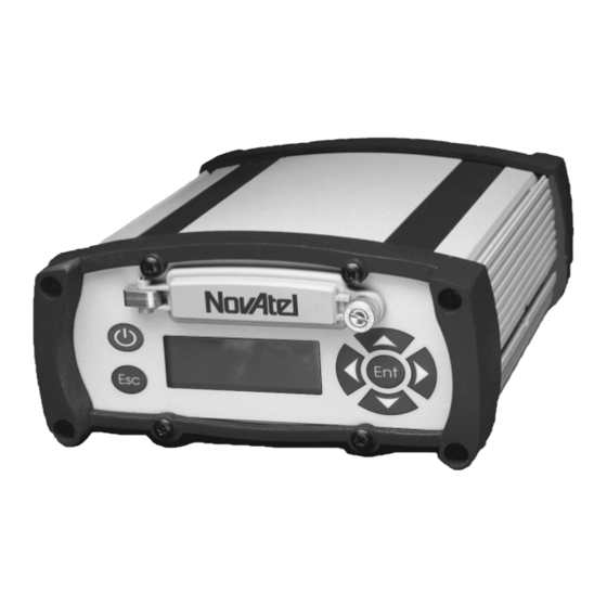
- Page 10 Figures DL-4 Receiver ........................15 Typical DL-4 Setup - Office ..................... 19 Typical DL-4 Setup - Field ....................22 Close-up of Ports on Back End-Cap ................24 Opening the Compact Flash Card Door ................29 DL-4 Front End-Cap ....................... 30 LCD Areas ........................
-
Page 11: Customer Service
Firmware updates and upgrades are accomplished through NovAtel authorized dealers. Contact your local NovAtel dealer first for more information. To locate a dealer in your area or if the problem is not resolved, contact NovAtel Inc. directly using one of the following methods: Call the NovAtel GPS Hotline at 1-800-NOVATEL (U.S. -
Page 12: Notices
(such as Belden #9945 or equivalent) when using the I/O strobe port. WARNING: Changes or modifications to this equipment not expressly approved by NovAtel Inc. could result in violation of Part 15 of the FCC rules. - Page 13 See also the RXSTATUS log on Page 171. The DL-4 can accept an input supply voltage in the range +7 to +18 V DC. This may not be the same range as other NovAtel products with which you are familiar. By default, operating the DL-4 below 6.5 V DC causes the unit to suspend operation.
-
Page 14: Foreword
Customer Service on Page 11. After the addition of accessories, an antenna and a power supply, the DL-4 will be ready to go. The DL-4 incorporates an LCD display on its front panel and this manual will take you through its menus and features, see LCD Menus on Page 39. -
Page 15: Introduction
Once you connect the DL-4 to an antenna and power supply, it begins operating as a fully functional GPS system (see Chapter 2, Typical Setup on Page 19 and Chapter 3, DL-4 Setup Considerations on Page 24, for more information on this topic). -
Page 16: Models And Features
Chapter 1 Introduction Models and Features The DL-4 is available in several different firmware models whose configurations may include other additional features. Some possible configurations can be seen in Table 1. Table 1: DL-4 Controller Models Model Name Firmware Feature... -
Page 17: Operating Modes
OPERATING MODES Whenever the DL-4 is connected to a power source (regardless of whether the DL-4 is turned “on” or “off”), it detects whether there is a host computer connected to one of its serial ports. For example, this host computer could be a PC running NovAtel DL4Tool, or a data logger running suitable software. -
Page 18: Accessories And Options
ACCESSORIES AND OPTIONS The DL-4 can be used with the following accessories: • NovAtel DL4Tool and GPSolution 4 – a suite of programs that allows you to plan your data collection trip, configure your DL-4 and archive your information sets •... -
Page 19: Typical Setup
Set Up DL-4 at the Office Figure 2 displays how you might typically set up the DL-4 at the office - for example, to load a schedule, or to transfer collected data to a PC. In this situation, the PC is connected to the COM1 port, and energy is supplied by means of a 12 V power supply. - Page 20 DL-4. See Serial Ports & Cables on Page 25. Press the power button or, if you are connected to the DL-4 via a terminal, hit the <Enter> key and wait for an RXSTATUSA log with a BOOTOK message to appear, see Page 171. If you are you are using the DL4Tool to communicate with the DL-4, this initial communication is handled by the software.
- Page 21 The sections of Chapter 3, DL-4 Setup Considerations starting on Page 24 give further details on Steps #2, #3 & #4, while Chapter 4, Using DL-4 starting on Page 32 is devoted to Step #5. Please refer to Volume 1 of the OEM4 Family Users’ Guide for more information on differential operation and message formats.
-
Page 22: Set Up Dl-4 As A Rover
Set Up DL-4 as a Rover Figure 3 displays how you might typically use the DL-4 in the field - for example, collecting data without the aid of base station corrections. In this situation, the GPS antenna is connected to the GPS port, and the power adapter is plugged into a 12 V power supply. - Page 23 Insert a Compact Flash Card into the DL-4 (see Using the Removable Compact Flash Memory Card on Page 28). Connect the output of a power source (e.g. battery) to the input power port of the DL-4 (see Power Port and Cable on Page 27).
-
Page 24: Dl-4 Setup Considerations
Chapter 3 DL-4 Setup Considerations Choose the Right Antenna The recommended antenna depends on which model of the DL-4 you purchased. Table 3 lists the allowable antenna types for each of the DL-4 models. Table 3: Allowable Antenna Types DL-4 Model... -
Page 25: I/O Port
DL-4 is part of an interconnected system composed of user devices that need to be synchronized with each other. For example, you could connect the DL-4 to an aerial camera in such a way that the DL-4 recorded its position whenever the shutter button was pressed. This port is not typically used for stand-alone applications. -
Page 26: Peripheral Power Supply Via The Aux Port
Cables are supplied to connect the receiver to a PC or modem. For further information on the signals, or connector pin-outs, for the serial ports or cables, please see Appendix A starting on Page 179. See Appendix B, Replacement Parts starting on Page 184, if you need to consult a list of NovAtel part numbers. -
Page 27: Power Port And Cable
Consider the case where the DL-4 is connected to two 12 V DC batteries. As described in the Status section of the LCD Menus chapter on Page 44, when the voltage drops on the first battery, the BATTERY status will change. -
Page 28: Using The Removable Compact Flash Memory Card
DL-4. A paired wire run represents a feed and return line; therefore, a 2-m wire pair represents a total wire path of 4 m (13.1’). For a DL-4 operating from a 12 V DC battery system, a power cable longer than 2.1 m (7‘) should not use a wire diameter smaller than that of 24 AWG. -
Page 29: Opening The Compact Flash Card Door
Compact Flash Card port Refer to the DL-4 commands and logs detailed in Chapter 8 and Chapter 9 of this manual. You have the flexibility of choosing the Compact Flash Card with the storage capacity that is the most appropriate for your needs, based on the selected logging rate. -
Page 30: Front End-Cap Functionality
Front End-Cap Functionality As shown in Figure 6, the DL-4’s front end-cap has an LCD display with a keypad including an Ent and Esc button, see Chapter 5, LCD Menus on Page 39, and a power button, see Sleep, Power Down and the Power Button following. -
Page 31: Power Modes
- for example, if a key is pressed on a handheld data logger that is plugged into one of the DL-4's serial ports. The time required to wake up is only a few seconds, but it may require an additional few minutes to initialize the GPS receiver and allow it to establish an initial time and position. -
Page 32: Using
4.1.1 Self-Test When the DL-4 is powered on by depressing the power button, a set of self-test functions are performed. Self-test failure of the power data card is indicated via the LCD panel status menu indicators and/or RXSTATUSA logs, see Page 171. Successful self-test of the power data card is indicated by a RXSTATUSA log with a BOOTOK message. -
Page 33: Communications With The Dl-4
Using DL-4 Chapter 4 of the OEM4 Family Users’ Guide). In the latter case, see Chapter 9, DL-4 Logs on Page 152, or refer to Volume 2 of the OEM4 Family Users’ Guide, for procedures and explanations related to data logging, and for further information on each of these logs. -
Page 34: Data Logging
PC for post-processing using the supplied DL4Tool software. DL-4 records raw data in the form of logs, which are written to the data file on a periodic basis. If you wanted to analyze the data in these logs yourself, the details of the logs are documented in Chapter 9, DL-4 Logs on Page 152. -
Page 35: Schedule Logging Operation
4.3.2 File Naming Conventions You can either provide a name for each data file in advance, or allow DL-4 to generate them automatically. You can only provide a file name when you are scheduling a single data collection event. If you are scheduling a series of events, you have to accept the DL-4's auto-generated names. -
Page 36: Data Storage Requirements
Should a conflict occur between an auto-generated file name or a file name specified in a scheduled entry, the DL-4 will resolve the conflict by creating a file name whose first character is a tilde ("~"), followed by a 7-digit random number, and a .PDC extension (e.g. ~9368412.PDC). -
Page 37: Memory Consumption - Typical Case For Rtk Survey (2 Second Rate)
L1/L2 operation. The file size will be no less than (942 kBytes/hour) x (8 hours) = 7536 kBytes = 7.36 MBytes. At this rate, an 8 MByte Compact Flash Card could hold approximately 8 hours of data. DL-4 User Manual Rev 3... -
Page 38: Errors
In this situation, allow for your data to be possibly reduced by several seconds up to a maximum of five minutes. To the extent possible, error messages attempt to describe the problem. See the RXSTATUS log on Page 171. DL-4 User Manual Rev 3... -
Page 39: Lcd Menus
Chapter 5 LCD Menus The front panel of DL-4 has an LCD with 6 interaction keys. The panel consist of four navigational, a combination edit/enter, and an escape key. The main functions of the LCD menu are: • Status • GPS Data •... -
Page 40: Operation Indicator Display
LOGGING / SITE GROUP GROUP / LOGGING GROUP / LOGGING / SITE SCHED SCHED / LOGGING SCHED / LOGGING SITE SCHED / GROUP SCHED / GROUP / LOGGING SCHED / GROUP / LOGGING / SITE DL-4 User Manual Rev 3... -
Page 41: Contrast
5.2.1 Normal Display When the DL-4 LCD is in normal mode, it will display as described on Pages 39 to 40. An example of a screen in normal display mode is shown in Figure 9. GPS DATA... -
Page 42: Scroll Pause Display
5.2.4 Edit Digit Display When the DL-4 LCD is in edit digit display mode, you are able to edit and set values in the screen. An editable screen has the upper middle box displayed in inverse video. Press the <Ent> key to cause the navigation aid arrows to turn to inverse video and for a cursor to appear under the first digit of the data value. -
Page 43: Edit Group Display
5.2.5 Edit Group Display When the DL-4 LCD is in edit group display mode, it is possible to select screen values. An editable screen has the upper middle box displayed in inverse video. Press the <Ent> key to cause the navigation aid arrows to turn to inverse video and for a cursor to appear under the first group. -
Page 44: Menus
This section describes, and graphically gives examples of, the main functionality menus and their sub- menus. 5.3.1 Status The STATUS functionality group provides diagnostic information about the DL-4. Its home screen gives you DL-4’s overall operational status and the current UTC time. Figure 14 shows the STATUS menus. STATUS CONTRAST LOGGING CONTRAST: 50 Ï... - Page 45 When there are no errors, there is an ‘OK’ message. • PDC ERR: The PDC status screen provides information on any PDC errors detected. When there are no errors, there is an ‘OK’ message. DL-4 User Manual Rev 3...
-
Page 46: View Gps Data
The VIEW GPS DATA functionality group allows you to view the position being determined by DL- 4. Its home screen gives you information to indicate the content of this menu group. Figure 15 on Page 47 shows the VIEW GPS DATA menus. DL-4 User Manual Rev 3... -
Page 47: Gps Data Menus
PDOP 2.5 GPS DATA CORR AGE LOGGING Int: 0.0 S Ï Ð SV:07 DGPS PDOP 2.5 GPS DATA >> LAT LOGGING N 45 15 36.0000 Í Î SV:07 DGPS PDOP 2.5 Figure 15: GPS Data Menus DL-4 User Manual Rev 3... - Page 48 • >>LAT: The scrolling pause screen provides a display as described in Section 5.2.3, Scroll Pause Display on Page 42. The values are displayed for 2 seconds before switching to the next value. DL-4 User Manual Rev 3...
-
Page 49: Configure Base
"edit by group" method, see Section 5.2.5, Edit Group Display on Page 43 for an explanation of the operation. Example message formats are RTCM, RTCA, and CMR. Refer to Volume 1 of the OEM4 Family User’s DL-4 User Manual Rev 3... -
Page 50: Config Logging
The CONFIG LOGGING functionality group provides information about the options which enable you to control logging to DL-4 using log groups or the scheduler. Its home screen gives you information to indicate the content of this menu group. Figure 17 shows the CONFIG LOGGING menus. -
Page 51: Config Sites
• PICK: The pick screen allows you to select the schedule, which is always the first choice on the list, or one of the log groups installed on the DL-4. You can select SCHEDULE or a log group by using the "edit by group" method, see Section 5.2.5, Edit Group Display on Page 43 for an explanation of the operation. -
Page 52: Configure Ports
5.3.6 Configure Ports The CONFIG PORTS functionality group allows you to configure the communication ports on DL-4. Its home screen gives you information to indicate the content of the functionality group. Figure 19 shows the CONFIG PORTS menus. CFG COM... -
Page 53: Commands
The port accepts/generates CMR corrections 5.3.7 Commands The COMMANDS functionality group allows you to execute selected basic DL-4 commands. Its home screen gives you information to indicate the content of the functionality group. Figure 20 shows the COMMANDS menus. DL-4 User Manual Rev 3... -
Page 54: Commands Menus
Ï Ð SV:07 DGPS PDOP 2.5 COMMAND MODELS LOGGING MOD:RT2 Í Ï Ð Î SV:07 DGPS PDOP 2.5 COMMAND AUTH CODE LOGGING AUTHCODE1234567 Í Ï Ð Î SV:07 DGPS PDOP 2.5 Figure 20: Commands Menus DL-4 User Manual Rev 3... -
Page 55: File Operations
As seen from Figure 20, there are four COMMANDS menu categories: • SLEEP: The edit sleep screen gives you the option of allowing the DL-4 to go to sleep or not. This is especially useful when you are using the DL-4 for a longer period of time than it takes for the device to go into sleep mode. -
Page 56: File Operations Menus
• APPLY: This screen allows you apply the choices in the preceding screens. You can choose YES or NO by using the "edit by group" method, see Section 5.2.5, Edit Group Display on Page 43 for an explanation of the operation. DL-4 User Manual Rev 3... -
Page 57: Software Programs
This unique feature means that upgrading the firmware is equivalent to getting a DL-4 with an entirely different set of features. Upgrading can be done anytime, anywhere, without any mechanical procedures whatsoever. New firmware can be transferred to the DL-4 through a serial port, immediately making the unit ready for operation at a higher level of performance. - Page 58 To update your DL-4 receivers to the latest firmware follow the steps below. You must install WinLoad to complete these instructions: Connect your DL-4 to the COM1 port of your PC, but do NOT supply the receiver with power (do not install batteries or supply the receiver with external power).
- Page 59 You will be prompted to make sure that the unit is powered off. At this point, make sure that the DL-4 is off and that you have not installed batteries or supplied the unit with external power. When you are sure the unit is not connected to a power supply, click <OK>.
- Page 60 − OEM4 firmware WARNING!: Do not turn off power to the DL-4 or PC until the update/upgrade process is completed. If you do turn off power before WinLoad is finished, the DL-4 may need to be returned. When finished (approximately 5-6 minutes), you will once again be requested to power off the DL-4.
- Page 61 WinLoad’s main window will read Script Completed Successfully. However, to ensure that the update/upgrade is complete, you should check the firmware version using the Windows HyperTerminal located on your PC. Proceed to the following section for instructions on using the HyperTerminal. DL-4 User Manual Rev 3...
-
Page 62: Using The Hyperterminal
In the Connect To dialog box, choose COM1 from the Connect Using list. Click <OK>. In the COM1 Properties dialog box, set the following: Bits Per Second: 9600, Data Bits: 8, Parity: None, Stop Bits: 1, Flow Control: Hardware. Click <OK>. DL-4 User Manual Rev 3... - Page 63 Click on the <OK> button at the bottom of the ASCII Setup dialog box. As well, click the <OK> button at the bottom of the New Connection Properties dialog box to return to the HyperTerminal window. DL-4 User Manual Rev 3...
- Page 64 Chapter 6 Software Programs Connect a power supply to the DL-4 and power on the DL-4 using its power button. After the DL-4 is powered on, the HyperTerminal window will display information as it communicates with the DL-4. Once communication is established, type Log Version in the HyperTerminal window to display the version information for the DL-4.
- Page 65 The serial number of the update must appear in the VERSION body. ENCLOSURE "" " NPV00450006" "" "" "" "" "" Select Call | Disconnect to end your session in HyperTerminal, and select File | Exit to close HyperTerminal. Disconnect the power supply from the DL-4. DL-4 User Manual Rev 3...
-
Page 66: Dl4Tool
DL4Tool is a powerful program which allows editing of schedules and log groups, uploading these to a DL-4 and downloading data from the Compact Flash Card to your PC. DL4Tool is easy to use and learn, while still providing a wide range of features and flexibility. -
Page 67: Exiting Dl4Tool
7.2.1 Receiver Groups To schedule your DL-4 receiver to automatically start logging data at a specific time, you must create a receiver group, include it in a schedule and transfer it to the receiver. When configuring your receiver, you can define the groups settings to determine the type of information the receiver collects. -
Page 68: Group Editor Dialog
Position Tab on Page 72, Site, see Site Tab on Page 73 and Interface, see Interface Tab on Page 75. Click the OK button to save your changes or the Cancel button to discard your changes and return to the main DL4Tool window. DL-4 User Manual Rev 3... -
Page 69: Add Log
Choose a log output format from the Format list. The Raw option should be chosen for transmitting differential corrections. A log’s interval information is what determines when and how often the DL-4 receiver will collect that log’s information. For example, if the interval for the range measurements log (RANGECMP) is set to On Time 2, the receiver will log range measurements every two seconds. -
Page 70: Log Intervals
The Edit Log dialog works in the same way as the Add Log dialog. Refer to the previous page for details. To delete a selected log from the current group, click on the Delete button. DL-4 User Manual Rev 3... - Page 71 DGPS_BASE ..... Use this group for a DGPS base receiver sending L1 code-only RTCM messages. All data is sent to COM port 2 Type of Information Description RTCM1 RTK differential corrections received every second ontime 1.0 DL-4 User Manual Rev 3...
-
Page 72: Receiver
2. The base station’s coordinates must be entered or you must select the option for a base station’s coordinates to be computed (based on meeting standard deviation or time interval criteria). DL-4 User Manual Rev 3... -
Page 73: Position Tab
If you check the Automatically Log Site On Startup check box, the group mode is set to static, a SITE ENTER command, see Page 136, is executed on startup, and the site is configured with parameters from the Site Information panel (if the Include Site Information check box is selected), or with a DL-4 User Manual Rev 3... - Page 74 Minimum Satellites ..Select a number from 1 to 9 for the minimum number of satellites. The default is 4. Elevation Mask ....Choose an integer value for the elevation mask angle between 0 and 90 degrees. The default is 0. DL-4 User Manual Rev 3...
-
Page 75: Interface Tab
Figure 28: Interface Tab This tab allows you to specify what type of data a particular port on the DL-4 can transmit and receive. The receive type (RX) tells the receiver what type of data to accept on the specified port. The transmit type (TX) tells the receiver what kind of data it can generate. -
Page 76: Schedule Editor
<Edit> ..... Edit a schedule. <Delete> ....Delete a schedule. <Load Defaults> ..Schedule only the default POWERUP group. <Close> ....Closes the Edit Receiver Schedule dialog and returns you to the main DL4Tool window. DL-4 User Manual Rev 3... -
Page 77: Schedule Entry
Groups on Page 67. Figure 30: Schedule Entry The group Name edit box is not editable. To rename the group you must access it through the Group Editor dialog box (see Section 7.2.1, Receiver Groups on Page 67). DL-4 User Manual Rev 3... - Page 78 A conflict error message will appear if you choose a time span in the Start or Stop fields that conflicts with another schedule. An example is shown in Figure 31, Conflict Example on Page 79. DL-4 User Manual Rev 3...
-
Page 79: Conflict Example
7.2.2.1.1 DL-4 Receiver Auto-Generated File Names If you leave the File field blank in the Schedule Entry dialog of the DL4Tool, the DL-4 will give your session an auto-generated filename using the following convention (the DL-4 receiver does this but the DL4Tool software does not). -
Page 80: Auto-Generated File Name Conventions
Chapter 7 DL4Tool • Characters 1 through 4 of the base is the last four digits of the DL-4 serial number. • Characters 5 through 7 of the base is the UTC day-of-year (001 - 366). • Character 8 of the base is the session id, an alphanumeric character in sequence 0, 1, 2, ..., 9, A, B, C, ..., Z, and starting with 0 for the first session of a UTC day. -
Page 81: Dl4Tool Receiver Communications
You can use the DL4Tool utility to manage and transfer files between the Compact Flash Card on the DL-4 and your PC. Connect your DL-4 receiver to your PC (see Section 2.1, Set Up DL-4 at the Office on Page 19 for instructions). -
Page 82: Upload Dialog Before (Left) And After (Right)
Delete groups or the schedule table from the Compact Flash Card by clicking on the Delete button. Deletion of a group will fail if that group is used in the DL-4 current schedule. In this case, you can delete the DL-4 schedule first and then delete the DL-4 group(s). -
Page 83: Download File From The Receiver To The Pc
DL4Tool Chapter 7 viewed. The Close button disconnects the DL-4 (if connected), closes the Upload dialog and returns you to the main DL4Tool window. 7.3.3 Download File from the Receiver to the PC Click on the Download button in the main DL4Tool window. The Download dialog will appear as seen in Figure 34. - Page 84 <Cancel> ....this option cancels the file transfer to the PC The Close button stops any current transfer or attempt to connect to the receiver, closes the Upload dialog and returns you to the main DL4Tool window. DL-4 User Manual Rev 3...
-
Page 85: Dl-4 Commands
Chapter 8 DL-4 Commands The DL-4 firmware implements the commands in Table 14 (repeated in Table 15 on Page 87 in the order of their binary messages IDs), in addition to the OEM4 GPSCard command set. Table 14: DL-4 Commands in Alphabetical Order... - Page 86 Chapter 8 DL-4 Commands Message ID ASCII Command Description groupuse Group configuration macro to execute DL-4 commands logfile Manual file logging control methumid Specify air humidity metpress Specify air pressure mettemp Specify ambient temperature project Project-related parameters rename Rename a file stored in the compact flash card...
-
Page 87: Dl-4 Commands In Order Of Their Message Ids
DL-4 Commands Chapter 8 Table 15: DL-4 Commands in Order of their Message IDs Message ID ASCII Command Description reset OEM4 reset with DL-4 features freset Factory reset auxcom Specify settings for the auxiliary serial port battery Control use of the power source(s) - Page 88 The arguments for each of these commands are described in the following sections. For a complete listing and description of the other commands that the DL-4 is capable of processing, please consult Volume 2 of the OEM4 Family User’s Guide.
-
Page 89: Syntax Conventions
Courier font is used to illustrate program output or user input. Data format definitions, as specified in the “Format” field, are detailed in Volume 2 of the OEM4 Family User Manual. Note that all binary data is little-endian byte-ordered. DL-4 User Manual Rev 3... -
Page 90: Audio
Volume Ulong none Pitch 0 (no change) Ulong none H+12 Table 16: Audio Event Binary Value ASCII Value Description NOTE note event, 2 beeps WARNING warning event, 3 beeps ERROR error event, 4 beeps DL-4 User Manual Rev 3... -
Page 91: Audible Annunciator Volume Levels
Power button stuck error periodic a. Periodic duration means a beep pattern repeating itself for as long as the condition persists. Single duration means one beep pattern when the condition first occurs. DL-4 User Manual Rev 3... -
Page 92: Auxbuf
Bytes Format Units Offset Not Specified Header Parameter Update, see Page 111 Enum none Size ULong bytes Table 20: AUXBUF Default Configuration Parameter Power-On Freset Stored in NVM Maximum packet size no change 0 (maximum) DL-4 User Manual Rev 3... -
Page 93: Auxcom
Note that the DL-4 hardware supports only the RTS portion of hardware handshaking, i.e. the DL-4 is capable of controlling the RTS line to flow-control the device connected to AUX, but the device can not flow-control the DL-4. -
Page 94: Parity
CTS/RTS hardware handshaking Table 23: AUXCOM Default Configuration Parameter Power-On Freset Stored in NVM baud rate no change 9600 parity no change data bits no change stop bits no change handshake no change echo no change DL-4 User Manual Rev 3... -
Page 95: Auxmark
Chapter 8 AUXMARK The auxmark command allows you to request that a MARK signal be sent to the DL-4’s internal OEM4 family card when an AUX packet is produced. A user can then trigger the generation of messages when the MARK signal is sent to the OEM4 (see the ONMARK trigger in the LOG command, Volume 2 of the OEM4 Family Users’... -
Page 96: Auxstart
Enum none Parameter Update Table 43 on Page 111 Size ULong bytes Sequence Hexbyte none Table 25: AUXSTART Default Configuration Parameter Power-On Freset Stored in NVM start-sequence size no change start sequence no change none DL-4 User Manual Rev 3... -
Page 97: Auxstop
Enum none Parameter Update Table 43 on Page 111 Size ULong bytes Sequence Hexbyte none Table 26: AUXSTOP Default Configuration Parameter Power-On Freset Stored in NVM stop-sequence size no change stop sequence no change none DL-4 User Manual Rev 3... -
Page 98: Auxtime
Bytes Format Units Offset Not Specified Header Parameter Update, see Table 43 Enum none on Page 111 Timeout ULong Table 27: AUXTIME Default Configuration Parameter Power-On Freset Stored in NVM timeout no change 1000 ms DL-4 User Manual Rev 3... -
Page 99: Battery
6000 and 15000 mV. If the DL-4 is powered on and the power source goes below the cutoff voltage, the DL-4 will shut off. If the DL-4 is not powered on, the applied power source must be 0.5 V above the cutoff voltage before the DL-4 can turn on. -
Page 100: Action Versus Power Source Selection
ASCII Value Description Use the source CUTOFF Set battery cutoff Table 30: Power Source Mode Binary Value ASCII Value Description The A battery or DC supply The B battery or DC supply Reserved AUTO Auto detect DL-4 User Manual Rev 3... -
Page 101: 8.10 Currentfile
0. Packet size is defined in the file log definition. • Issued without specifying the dump mode, defaults the dump mode to all. Syntax currentfile currentfile file [all|{single [packet_id]}] Message Id = 185 DL-4 User Manual Rev 3... -
Page 102: 8.11 Currentgroup
[group] Message Id = 186 Value Used if Field Data Bytes Format Units Offset Not Specified Header Group Name Char[] none Table 34: CURRENTGROUP Default Configuration Parameter Power-On Freset Stored in NVM currentgroup none none DL-4 User Manual Rev 3... -
Page 103: 8.12 Del
Delete Target, see Table 35 Enum none File Char[] none Table 35: Delete Target Binary Value ASCII Value Description Delete all files FILE Delete the filename specified A default configuration is not applicable to this command. DL-4 User Manual Rev 3... -
Page 104: 8.13 Disk
The disk command allows you to carry out flash-disk (compact flash) maintenance. The disk format command formats the flash disk for use with DL-4. The format sequence erases all data previously stored on the disk. This operation is not reversible. -
Page 105: 8.14 Freset
Chapter 8 8.14 FRESET The OEM-4 freset command is extended to include DL-4 features. An additional “target” field controller (value = 10), resets only the controller NVM, thereby resetting all parameters indicated in this document as “Stored in NVM” to factory defaults. Issuing the freset command with the “target”... -
Page 106: 8.15.1 Factory-Reset Default Group
IONUTCB ONCHANGED • RTCAOBS ONTIME 1 • RTCAREF ONTIME 10 • RXSTATUSEVENTB ONNEW • HWLEVELSB ONTIME 60 • POSAVE 0.01 • INTERFACEMODE COM2 NONE RTCA OFF You may edit or delete the factory-reset DEFAULT group. DL-4 User Manual Rev 3... -
Page 107: Groupantheight Default Configuration
Not Specified Header , see Enum none Parameter Update Table 43 on Page 111 Group name Char[] none AntHeight Float none H+16 Table 39: GROUPANTHEIGHT Default Configuration Parameter Power-On Freset Stored in NVM antheight no change DL-4 User Manual Rev 3... -
Page 108: Groupantsn Default Configuration
Parameter Update, see Table 43 on Enum none Page 111 Group name Char[] none AntSn: Antenna Serial Number Char[] none H+16 Table 40: GROUPANTSN Default Configuration Parameter Power-On Freset Stored in NVM antsn no change DL-4 User Manual Rev 3... -
Page 109: Groupanttype Default Configuration
Not Specified Header Parameter Update, see Table 43 Enum none on Page 111 Group name Char[] none AntType Char[] none H+16 Table 41: GROUPANTTYPE Default Configuration Parameter Power-On Freset Stored in NVM anttype no change DL-4 User Manual Rev 3... -
Page 110: Groupdgpstxid Default Configuration
Group name Char[] none DGPS Type, see Table 92 on Page 168 Enum none H+16 Char[] none H+20 Table 42: GROUPDGPSTXID Default Configuration Parameter Power-On Freset Stored in NVM type no change AUTO no change DL-4 User Manual Rev 3... -
Page 111: Parameter Update
Set the parameter for a group to the default Set the parameter for a group CLEAR Clear the parameter from a group Table 44: GROUPECUTOFF Default Configuration Parameter Power-On Freset Stored in NVM ecutoff no change DL-4 User Manual Rev 3... -
Page 112: Groupfixpos
H+16 Longitude Double degrees H+24 Height Double degrees H+32 Reserved for future use none H+40 none H+44 Table 45: GROUPFIXPOS Default Configuration Parameter Power-On Freset Stored in NVM Fixed Position Configuration no change CLEAR DL-4 User Manual Rev 3... -
Page 113: Groupinterfacemode
H+20 see Table 90 on Page 160 tx_type – Serial Port Interface Mode, NOVATEL Enum none H+24 see Table 90 on Page 160 responses – OnOff, see Table 81 on Enum none H+28 Page 147 DL-4 User Manual Rev 3... -
Page 114: Grouplog
(the destination which is specified at the time the group is executed). See Table 87 on Page 159 for a list of valid port identifiers. • message specifies a valid ASCII or binary DL-4 message (abbreviated-ASCII messages are not supported) which is to be requested when the group is executed. -
Page 115: Groupuse Translation
Volume 2 of the OEM4 Family Users’ Guide) Period Float seconds H+28 Table 47: GROUPLOG Default Configuration Parameter Power-On Freset Stored in NVM no change See Section 8.15.1, Factory-Reset configuration DEFAULT Group on Page 106 DL-4 User Manual Rev 3... -
Page 116: Groupmode
Table 48: Group Mode Binary Value ASCII Value Description STATIC Set group mode to static KINEMATIC Set group mode to kinematic Table 49: GROUPMODE Default Configuration Parameter Power-On Freset Stored in NVM Group Mode no change KINEMATIC DL-4 User Manual Rev 3... -
Page 117: Groupposave
Field Data Bytes Format Units Offset Not Specified Header Parameter Update, see Table 43 Enum none on Page 111 Group name Char[] none MaxTime Double hours H+16 MaxHorStd Double none H+24 MaxVerStd Double none H+32 DL-4 User Manual Rev 3... -
Page 118: Groupsatlimit
Not Specified Header Parameter Update, see Enum none Table 43 on Page 111 Group name Char[] none Satellite Limit none H+16 Table 51: GROUPSATLIMIT Default Configuration Parameter Power-On Freset Stored in NVM Satellite Limit no change DL-4 User Manual Rev 3... -
Page 119: Groupsitename
Offset Header Parameter Update, see Table 43 on Page 111 Enum none Group name Char[] none Site Name Char[] none H+16 Table 52: GROUPSITENAME Default Configuration Parameter Power-On Freset Stored in NVM sitename no change DL-4 User Manual Rev 3... -
Page 120: Groupsitenumber
Not Specified Header Parameter Update, see Table 43 Enum none on Page 111 Group name Char[] none Site Number Char[] none H+16 Table 53: GROUPSITENUMBER Default Configuration Parameter Power-On Freset Stored in NVM sitenumber no change DL-4 User Manual Rev 3... -
Page 121: Groupuse
DL-4 Commands Chapter 8 8.29 GROUPUSE The groupuse command is a macro which uses the group configuration to execute a set of DL-4 commands. The groupuse start command executes the start macro for the group named groupname, with the default log destination set to dst. If dst is not specified, THISPORT is assumed. If any message-logging destinations are FILE_n, filename is associated with these destinations. -
Page 122: Group Action
9, Table 87 on Page 159 Filename Char[] none H+20 Table 54: Group Action Binary Value ASCII Value Description START Start the specified group STOP Stop the specified group A default configuration is not applicable to this command. DL-4 User Manual Rev 3... -
Page 123: Logfile
“pdc”. If file is not specified, a default filename is created for the logfile as follows: • The first four characters is taken from the last four digits of the DL-4 serial number. -
Page 124: Log File Action
Table 55: Log File Action Binary Value ASCII Value Description OPEN Associate the specified channel with a file. CLOSE Terminate the specified channel-file association. Table 56: LOGFILE Default Configuration Parameter Power-On Freset Stored in NVM logfile none none DL-4 User Manual Rev 3... -
Page 125: Methumid
Data Bytes Format Units Offset Not Specified Header Parameter Update, see Enum none Table 43 on Page 111 Humidity Float percent Table 57: METHUMID Default Configuration Parameter Power-On Freset Stored in NVM methumid clear clear DL-4 User Manual Rev 3... -
Page 126: Metpress
Field Data Bytes Format Units Offset Not Specified Header Parameter Update, see Enum none Table 43 on Page 111 Pressure Float Table 58: METPRESS Default Configuration Parameter Power-On Freset Stored in NVM metpress clear clear DL-4 User Manual Rev 3... -
Page 127: Mettemp
Data Bytes Format Units Offset Not Specified Header Parameter Update, see Table 43 Enum none on Page 111 Temperature Float Celsius Table 59: METTEMP Default Configuration Parameter Power-On Freset Stored in NVM metpress clear clear DL-4 User Manual Rev 3... -
Page 128: Project
Table 60: Project Action Binary Value ASCII Value Description Add a new project into the PDC (default) CLEAR Clear projects from the PDC Table 61: PROJECT Default Configuration Parameter Power-On Freset Stored in NVM project clear clear DL-4 User Manual Rev 3... -
Page 129: Rename
H+12 A default configuration is not applicable to this command. 8.36 RESET The OEM-4 reset command is extended to include DL-4 features. A default configuration is not applicable to this command. 8.37 SATLIMIT The satlimit command allows you to set the minimum number of SVs used in position solution, for a specific set of messages to be passed through a particular FILE_n virtual channel. -
Page 130: File Port Channel
FILE_ALL All virtual channels for file target FILE File target, virtual channel 0 … … FILE_31 File target, virtual channel 31 Table 63: SATLIMIT Default Configuration Parameter Power-On Freset Stored in NVM satlimit clear clear DL-4 User Manual Rev 3... -
Page 131: Schedule
Execution of this command does not cause the execution of the groupuse stop command. Normal group scheduler operation resumes at the end of the aborted event. This command fails if executed while a schedule event is not in progress. DL-4 User Manual Rev 3... -
Page 132: Dl-4 Group Scheduler Behavior
Chapter 8 DL-4 Commands Figure 35: DL-4 Group Scheduler Behavior Disabled schedule enable schedule disable, scheddule clear Enabled event interval start session schedule abort Session in progress schedule disable, schedule clear, shutdown out of event interval stop session In the diagram above: schedule enable –... -
Page 133: Schedule Mode
Clear schedules from PDC ABORT Abort scheduling on PDC ENABLE Enable scheduling on PDC DISABLE Disable scheduling on PDC Table 65: SCHEDULE Default Configuration Parameter Power-On Freset Stored in NVM schedule table no change clear DL-4 User Manual Rev 3... -
Page 134: Scheduleadd
Syntax scheduleadd groupname starttime endtime [filename] Message Id = 152 Value Used if Field Data Bytes Format Units Offset Not Specified Header GroupName Char[] StartTime Char[] (dddddddhhmm) H+12 EndTime Char[] (dddddddhhmm) H+24 FileName Char[] H+36 DL-4 User Manual Rev 3... -
Page 135: Scheduledel
Page 173, which lists the schedule table. This operation is not reversible. Syntax scheduledel index Message Id = 154 Field Data Bytes Format Units Offset Header Index Ulong A default configuration is not applicable to this command. DL-4 User Manual Rev 3... -
Page 136: Site
SVs used in generation of these logs > 0 within 30 seconds before a site leave but such logs are received at some time after a site enter command): • both, the SITE_ST_STARTTRUNCATE and SITE_ST_ENDTRUNCATE bits is set in the SiteStatus field of the sitedef log DL-4 User Manual Rev 3... -
Page 137: Site Mode
Binary Value ASCII Value Description ENTER Enter a site into PDC (default) LEAVE Leaving site CANCEL Cancel this site from the PDC Table 67: SITE Default Configuration Parameter Power-On Freset Stored in NVM site cancel cancel DL-4 User Manual Rev 3... -
Page 138: Siteupdatenumber
Parameter Update, see Enum none Table 43 on Page 111 Site Number Char[] none Reserved for future use Char[] none H+12 Table 68: SITEUPDATENUMBER Default Configuration Parameter Power-On Freset Stored in NVM Site Number clear clear DL-4 User Manual Rev 3... -
Page 139: Siteupdatename
Parameter Update, see Enum none Table 43 on Page 111 Site Name Char[] none Reserved for future use Char[] none H+36 Table 69: SITEUPDATENAME Default Configuration Parameter Power-On Freset Stored in NVM Site Name clear clear DL-4 User Manual Rev 3... -
Page 140: Siteupdateantheight
Not Specified Header Parameter Update, see Enum none Table 43 on Page 111 AntHeight Float none Reserved for future use Char[] none Table 70: SITEUPDATEANTHEIGHT Default Configuration Parameter Power-On Freset Stored in NVM AntHeight clear clear DL-4 User Manual Rev 3... -
Page 141: Siteupdateanttype
Parameter Update, see Table 43 on Enum none Page 111 Antenna Type Char[] none Reserved for future use Char[] none H+20 Table 71: SITEUPDATEANTTYPE Default Configuration Parameter Power-On Freset Stored in NVM AntType clear clear DL-4 User Manual Rev 3... -
Page 142: Siteupdateattribute
Not Specified Header Parameter Update, see Enum none Table 43 on Page 111 Attribute none Reserved for future use Char[] none Table 72: SITEUPDATEATTRIBUTE Default Configuration Parameter Power-On Freset Stored in NVM Attribute clear clear DL-4 User Manual Rev 3... -
Page 143: Sleep
DL-4 Commands Chapter 8 8.47 SLEEP The sleep command allows you to control automatic power-off of DL-4 subsystems for power- conservation purposes. Specified without arguments, the sleep command enables sleep mode on the receiver and simulates a timeout on the receiver activity sources (see the sleepmask command on Page 144). If other conditions for turning the receiver off due to inactivity are satisfied (i.e. -
Page 144: Sleepmask
The sleepmask set|clear command configures the receiver to use or ignore, respectively, activity on the specified activity source for time-out and turning ON. The receiver keyword has no effect on this command. It is supported for future expansion purposes. DL-4 User Manual Rev 3... -
Page 145: Activity Sources
Reserved for future use. a. This activity source is not monitored while the receiver is OFF. Table 78: SLEEPMASK Default Configuration Parameter Power-On Freset Stored in NVM Sleepmask no change Default, see Table 76 on Page 144 DL-4 User Manual Rev 3... -
Page 146: Softpower
Specified with the persist argument as off, the port power is disabled while the receiver is OFF (i.e. if AUX power is enabled, AUX power is disabled while the receiver is OFF, and is re-enabled when the receiver is turned ON). DL-4 User Manual Rev 3... -
Page 147: Peripheral Power
Table 81: On/Off Binary Value ASCII Value Description Set state to off Set state to on Table 82: VOUT Default Configuration Parameter Power-On Freset Stored in NVM Enable no change Persist no change DL-4 User Manual Rev 3... -
Page 148: Write
Message Id = 257 Field Data Bytes Format Units Offset Header Previous Ulong Bytes Type Ulong Length Ulong Bytes Data Max. 1024 Char[] H+16 A default configuration is not applicable to this command. DL-4 User Manual Rev 3... -
Page 149: Writefile
Message Id = 204 Field Data Bytes Format Units Offset Header Filename Char[] Length Ulong Bytes H+12 Data Max. 1024 Char[] H+16 A default configuration is not applicable to this command. DL-4 User Manual Rev 3... -
Page 150: Writefilehex
Message Id = 240 Field Data Bytes Format Units Offset Header Filename Char[] Length Ulong Bytes H+12 Data Max. 1024 Hexbyte H+16 A default configuration is not applicable to this command. DL-4 User Manual Rev 3... -
Page 151: Writehex
Message Id = 205 Field Data Bytes Format Units Offset Header Previous Ulong Bytes Type Ulong Length Ulong Bytes Data Max. 1024 Hexbyte H+16 A default configuration is not applicable to this command. DL-4 User Manual Rev 3... -
Page 152: Dl-4 Log
Chapter 9 DL-4 Logs The DL-4 firmware generates the logs in Table 83 (repeated in Table 84 on Page 153 in the order of their binary messages IDs), in addition to those of the OEM4 GPSCard log set. Table 83: DL-4 Logs in Alphabetical Order... -
Page 153: Dl-4 Logs In Order Of Their Message Ids
COMCONFIG COM port configuration For a complete listing and description of the other logs that the DL-4 is capable of generating, please consult Volume 2 of the OEM4 Family Users’ Guide. It also contains procedures and explanations related to data logging. -
Page 154: Pdc Files
Version number Revision byte Revision number 0 to 99 Reserved byte Reserved for future use The HDRB and GRPB logs are binary versions of the HDRA and GRPA logs described in the following sections. DL-4 User Manual Rev 3... -
Page 155: Audiodef Audible Annunciator Settings
Page 90 Volume Event volume as defined in AUDIO Ulong on Page 90 Pitch Event pitch as defined in AUDIO Ulong H+12 on Page 90 Next Audio Event, offset = H + 16 + (N*12) DL-4 User Manual Rev 3... -
Page 156: User Manual Rev
H+25 StopSize Stop sequence length Uchar bytes H+28 Stop Stop sequence Hexbyte H+29 Time Time out Ulong H+32 PacketSize Maximum packet size Ulong bytes H+36 Mark OnOff, see Table 81 on Enum H+40 Page 147 DL-4 User Manual Rev 3... -
Page 157: Batstatus Power Source Status
Bit = 0 Bit = 1 0x00000001 Reserved 0x00000002 Peripheral power on AUX port flag disabled enabled 0x00000004 Reserved 0x00000008 Peripheral power on AUX port persistent flag not persistent persistent Unused bits are reserved for future use. DL-4 User Manual Rev 3... -
Page 158: Comconfig Com Port Configuration
Table 90, Serial Port Interface Modes on Page 160 responses Responses are turned on or off Enum H+44 0 = OFF 1 = ON 14… Next port offset = H – 40 + (#port x 44) DL-4 User Manual Rev 3... -
Page 159: Serial Port Identifiers
File on the compact flash card, virtual port 31 Table 88: Parity Binary ASCII Description No parity Even parity Odd parity Table 89: Handshaking Binary ASCII Description No handshaking XON/XOFF software handshaking CTS/RTS hardware handshaking DL-4 User Manual Rev 3... -
Page 160: Currentset "Currentx" Command Configuration
ASCII Mode Name Binary Value Description NONE The port accepts/generates nothing NOVATEL The port accepts/generates NovAtel commands and logs RTCM The port accepts/generates RTCM corrections RTCA The port accepts/generates RTCA corrections The port accepts/generates CMR corrections CURRENTSET “CurrentX” Command Configuration... -
Page 161: Dirent Pc Card File List
Filename Char[] none SizeBytes Ulong bytes H+12 SizePackets Ulong packets H+16 Date of Last Change Ulong yyyymmdd H+20 Time of Last Change Ulong hhmmss H+24 Up to 1000 files can be listed via this facility. DL-4 User Manual Rev 3... -
Page 162: Filechannel Log File Channel Configuration
H+76 on Page 130 SatLimit Number of SV filter H+80 Reserved for future use Ulong H+84 Ulong H+88 FileName Name of open logfile Char H+92 Next File Port offset = H + 76 + (N*28) DL-4 User Manual Rev 3... -
Page 163: Filedump File Dump
“Length” field to determine the number of valid bytes in the “Data” field. Field Data Bytes Format Units Offset Header Packet ID Ulong Length Ulong Bytes Data Max. 1024 Hexbyte none DL-4 User Manual Rev 3... -
Page 164: Filehdr Logfile Header
File position of the first Ulong H+60 versionb log TimeP File position of the first Ulong H+64 timeb log ProjectP File position of the first Ulong H+68 projectdefb log GroupP File position of the first Ulong H+72 groupdefb log DL-4 User Manual Rev 3... -
Page 165: File Status
0x00000010 Flag to indicate if ionutca/b logs are present absent present in the file 0x00000020 Flag to indicate if bestposa/b and/or absent present rtkposa/b logs are present in the file DL-4 User Manual Rev 3... -
Page 166: Groupdef Log Group Configuration
H+68 Latitude Double (Degrees) H+72 Longitude Double (Degrees) H+80 Height Double H+88 Site# Site number Char H+96 SiteName Site name Char H+104 DGPS Type DGPS ID type, see Enum H+136 Table 92 on Page 168 DL-4 User Manual Rev 3... - Page 167 Serial port identifier, see Enum H+180 Table 87 on Page 159. Reserved for future use Float H+184 Ushort H+188 Uchar H+190 Uchar H+191 Next Log Spec Offset = H + 168 + (N * 24) DL-4 User Manual Rev 3...
-
Page 168: Dgps Type
COM2 Tx interface mode – the 3-bit binary value corresponds to the values in “Serial Port Interface Modes” 0xe0000000 COM2 Rx interface mode – the 3-bit binary value corresponds to the values in “Serial Port Interface Modes” DL-4 User Manual Rev 3... -
Page 169: Hwlevels Hardware Levels
H+44 Reserved for future use Float H+48 ctrl temp DL-4 temperature Float Celsius H+52 disk space Remaining space on the compact Ulong bytes H+56 flash card Reserved for future use Float H+60 Float H+64 DL-4 User Manual Rev 3... -
Page 170: Metdef Meteorological Parameters
VALID 9.14 PROJECTDEF Project Definition Structure: Message ID = 156 Log Type: Polled Field Data Description Bytes Format Units Offset Header Project Project description Char Agency Agency description Char H+32 Observer Observer description Char H+64 DL-4 User Manual Rev 3... -
Page 171: Rxstatus Dl-4 Status
OEM4 Family Users’ Guide for details on this log, are defined as in Table 95 on Page 171 and Table 96 on Page 172, to indicate DL-4 functionality. The corresponding priority, set and clear masks can be defined via the STATUSCONFIG command, refer to Volume 2 of the OEM4 Family Users’... -
Page 172: Auxiliary 3 Status Word
Wireless interface card status fail 0x00002000 Flag to indicate if a timer fail occurred on fail last powerup 0x00004000 DL-4 low-power subsystem flag fail 0x00008000 Peripheral power overload flag overload 0x00010000 Logfile name conflict flag no conflict conflict DL-4 User Manual Rev 3... -
Page 173: Rxstatusevent Dl-4 Status Event Notification
DL-4 Logs Chapter 9 9.16 RXSTATUSEVENT DL-4 Status Event Notification The RXSTATUSEVENT log set, refer to the Volume 2 of the OEM4 Family Users’ Guide, is extended to indicate DL-4 functionality. 9.17 SCHDEF Schedule Table Entry Structure: Message ID = 151... -
Page 174: Sitedef Site Configuration
Bit Name Description Bit=0 Bit=1 0x00000001 SITE_ST_INVALID No valid logs logs received no logs 0x00000002 SITE_ST_STARTTRUNCATE Site occupation start not truncated truncated time truncation flag 0x00000004 SITE_ST_ENDTRUNCATE Site occupation end not truncated truncated time truncation flag DL-4 User Manual Rev 3... -
Page 175: Sleepmode Sleep Configuration
0x00000008 source masked source used 0x00000010 Reserved for future use. 0x00000020 Power button source masked source used 0x00000040 Log file open source masked source used 0x00000080 Schedule activity in progress/pending source masked source used DL-4 User Manual Rev 3... -
Page 176: Version Hw & Sw Versions And Serial Numbers
9.20 VERSION HW & SW Versions and Serial Numbers The Component Type of the VERSION log, refer to Volume 2 of the OEM4 Family Users’ Guide, is extended to include DL-4 information as in Table 99. Table 99: Component Type... -
Page 177: Technical Specifications
Typical values. Performance specifications are subject to GPS system characteristics, U.S. DOD operational degradation, ionospheric and tropospheric conditions, satellite geometry, baseline length and multipath effects. Assumes SA Off. Time accuracy does not include biases due to RF or antenna delay. In accordance with export licensing. DL-4 User Manual Rev 3... - Page 178 POWER MANAGEMENT If the DL-4 is connected to a 12 V battery, the lower cutoff voltage should be set to 10.5 V using the BATTERY command on Page 99 as the battery should not be allowed to discharge lower than 10.5 V.
-
Page 179: Dl-4 Serial Port Pin-Out Descriptions
Technical Specifications Appendix A A.3 Port Pin-Outs Table 100: DL-4 Serial Port Pin-Out Descriptions Connector COM1 COM2 Pin No. RXD1 RXD2 RXD3 TXD1 TXD2 TXD3 POUT RTS1 RTS2 RTS3 CTS1 CTS2 CTS3 Table 101: DL-4 I/O Port Pin-Out Descriptions DL-4 Connector Pin No. -
Page 180: Power Cable - Illustration
Appendix A Technical Specifications A.4 Cables A.4.1 Power Cable with Automotive Adapter (NovAtel part number 01017023) The power cable (with automotive adapter) is 2 meters (6.56 feet) long and has a 4-pin LEMO to automotive adapter socket (male plug) connector ends. -
Page 181: Y-Type Null Modem Cable
This cable supplied with the DL-4, see Figure 37, provides an easy means of communications with the DL-4 from a PC. The cable is equipped with a 9-pin connector at the DL-4 end which can be plugged into either COM1, COM2 or AUX. At the PC end, both a 9-pin and a 25-pin connector are provided to accommodate most PC serial (RS232) communication ports. -
Page 182: Straight Serial Cable
Straight Serial Cable (NovAtel part number 60723066) This cable can be used to connect the DL-4 to a modem or radio transmitter to propagate differential corrections. The cable is equipped with a male DB9 connector at the DL-4 end that should ideally be plugged into COM 2 on the receiver. -
Page 183: I/O Strobe Port Cable
I/O Strobe Port Cable (NovAtel part number 60723065) The DL-4 strobe lines can be accessed by inserting the male DB9 connector of the I/O strobe port cable into the I/O port. The other end of this cable is provided without a connector to provide flexibility. -
Page 184: Replacement Parts
Appendix B Replacement Parts The following are a list of the replacement parts available for your NovAtel GPS receiver. Should you require assistance or need to order additional components, please contact your local NovAtel dealer or Customer Service representative. B.1 DL-4 Cables... - Page 185 BATTERY 99 – delete 56 depleted batteries 27 differential – – cables 24 corrections 75 carrier-phase 16 operation 16 CD 57 digital 179 clock, internal 178 DIRENT 161 CMR 21 DISK 104 coaxial cable 26 DL-4 User Manual Rev 3...
- Page 186 53 – configure 49 GPSAntenna 184 contrast 41 GPSolution software 57 file operations 55 green indicator 25 GPS data 46 – GROUP 105 logging 50 – group 32 menu access 41 GROUPANTHEIGHT 107 ports 52 DL-4 User Manual Rev 3...
- Page 187 26 pin-outs 179 – – satellite 48 ports 24 SATLIMIT 129 communication 21 SCHEDULE 131 I/O 25 SCHEDULEADD 134 power 28 SCHEDULEDEL 135 RF 26 scheduling 32 serial 53 – scroll display 41 DL-4 User Manual Rev 3...
- Page 188 (TTFF) 177 transfer files 81 transmit 75 two power sources 27 type of corrections 49 – upgrades and updates 11 velocity 48 – voltage 27 Volume 2, OEM4 Family Users’ Guide 184 VOUT 146 DL-4 User Manual Rev 3...
- Page 189 Index DL-4 User Manual Rev 3...
- Page 190 OM-20000063 Rev 3 2003/04/01...
Need help?
Do you have a question about the DL-4 and is the answer not in the manual?
Questions and answers