
Related Manuals for Novatel GPStation


Summary of Contents for Novatel GPStation
- Page 1 Software Rev. 3.34 OM-20000014 Rev. 1.0 GPStation User Manual GPStation™ Products NovAtel Inc.
-
Page 2: User Manual
Information in this document is subject to change without notice and does not represent a commitment on the part of NovAtel Inc. The software described in this document is furnished under a license agreement or non-disclosure agreement. The software may be used or copied only in accordance with the terms of the agreement. It is against the law to copy the software on any medium except as specifically allowed in the license or non-disclosure agreement. -
Page 3: Table Of Contents
4 FIRMWARE UPGRADES & UPDATES Upgrading Using the $AUTH Command .........................17 Updating Using the “Loader” Utility........................18 Downloading Firmware Files ........................18 Using the Loader Utility ..........................19 APPENDIX A TECHNICAL SPECIFICATIONS APPENDIX B GPStation REPLACEMENT PARTS We Would Like To Hear From You... GPStation™ User Manual... - Page 4 Table of Contents TABLES 1 Feature Summary - GPStation Models..........................2 2 Straight Cable Pin Configurations ............................8 3 Null Modem Cable Pin Configurations ..........................9 4 I/O Port Pin-out Description............................10 FIGURES 1 Photograph of GPStation..............................1 2 GPStation Front End-cap..............................3 3 GPStation Rear End-cap..............................3 4 Typical GPStation Installation Configuration ........................4...
- Page 5 CONSEQUENTIAL DAMAGES OF ANY KIND OR NATURE DUE TO ANY CAUSE. There are no user serviceable parts in the GPStation and no maintenance is required. When the status code indicates that a unit is faulty, replace with another unit and return the faulty unit to NovAtel Inc.
- Page 6 You may photocopy and fax this page, call, or mail the above information to the address listed below. For customer support, contact the NOVATEL GPS Hotline at 1-800-280-2242 or 403-295-4900; send a fax to 403-295-4901; send e-mail to support@novatel.ca, visit our web site at www.novatel.ca; or write to: NovAtel Inc.
- Page 7 Notices FCC NOTICE FCC approval (Class A digital device) is pending. CAUTION ! Handle with Care Use Anti-Static Precautions GPStation™ User Manual...
-
Page 8: Foreword
FOREWORD Scope This manual provides sufficient information for the initial set-up and operation of the GPStation; its focus is on the user’s perspective for integration, evaluation, and operation purposes. It is beyond the scope of this manual to provide service or repair details. -
Page 9: Introduction
Model A030 Choke-ring Ground Plane - to reduce the effects of multipath reception • Model C005, C015, or C030 (5, 15 or 30 m length) coaxial cable - to connect the GPSAntenna to the GPStation After the addition of these accessories, together with user-supplied data communications equipment and a power supply, the GPStation will be ready for use. -
Page 10: Feature Summary - Gpstation Models
Exceptional acquisition and re-acquisition times are also a standard feature of this high-performance receiver. The GPStation is available in two models whose features are summarized in Table 1: Table 1 Feature Summary - GPStation Models... -
Page 11: Connections And Indicators
GPSAntenna. There is a LED above each serial port connector. If a LED glows red, data is being received by the GPStation on that port, while if a LED glows green, data is being transmitted by the GPStation on that port. -
Page 12: Hardware Configuration
2 – Hardware Configuration HARDWARE CONFIGURATION Installing the GPStation is a straightforward process. As shown in Figure 4, a minimum configuration is established with the following set-up: • Set up the GPSAntenna and optional choke-ring ground plane • Route and connect coaxial cable between the GPSAntenna and GPStation. -
Page 13: Cable Connection Considerations
The 501’s low-noise amplifier (LNA) boosts the power of the incoming signals by 23 dB to compensate for cable losses; if the losses are greater than this, excessive signal degradation will occur and the GPStation may not be able to meet its performance specifications. -
Page 14: Antenna Cable Considerations
It accepts a single input voltage between the range of +10 to +36 V DC. The power input is reverse polarity protected. Refer to the Power Requirements section of Appendix A for further information. The DC output of the autoranging AC/DC converter will meet the GPStation’s requirements for an input of 110 - 220 V NOTE: Operating the GPStation outside the specified input voltage range may result in damage to the GPStation, and/or unreliable data. -
Page 15: Serial Data Cables
AC plug SERIAL DATA CABLES Two serial data cables are supplied to connect the GPStation to a PC or modem. They are described as follows: • straight cable: 10-pin LEMO plug to 9-pin D-connector (DE9P plug); see Figure 6 & Table 2. This is used to connect the GPStation to a modem or radio transmitter to propagate the differential corrections. -
Page 16: Straight Serial Port Cable
Pin 3 Pin 4 Orange Pin 4 Pin 5 Yellow Pin 5 Pin 6 Green Pin 6 Pin 7 Blue Pin 7 Pin 8 Violet Pin 8 Pin 9 NULL Gray Pin 9 Pin 10 White (Not used) GPStation™ User Manual... -
Page 17: Null Modem Cable Pin Configurations
Pin 5 Yellow Pin 5 Pin 6 Green Pin 4 Pin 7 Blue Pin 8 Pin 8 Violet Pin 7 Pin 9 NULL Gray Pin 9 Pin 10 White (Not used) Pin 1 jumpered to Pin 6 GPStation™ User Manual... -
Page 18: I/O Strobe Port Cable
I/O STROBE PORT CABLE The I/O strobe lines can be accessed by inserting the 8-pin LEMO connector of the I/O strobe port cable (NovAtel p/n 01016330) into the I/O port. Figure 8 and Table 4 contain wiring and pin-out information on this cable. The other end of the cable is provided without a connector so that the user can provide an application-specific one;... -
Page 19: User-Supplied Radio Or Modem
NOTE: The accuracy of the OCXO is impaired by vibration and shock, so it is essential that the GPStation be at rest on a stable and secure surface during operation. The GPStation has rubber feet in order to reduce the effect of vibration. -
Page 20: Operation
OPERATION Before using the GPStation for the first time, ensure that you have set up your system as recommended in Section 2. The following instructions are based on a configuration such as that shown in Figure 9. It is assumed that a personal computer is used during the initial operation and testing for greater ease and versatility. -
Page 21: Communicating Using A Remote Terminal
NOTE: Although the GPStation can operate at bit rates as low as 300 bps, this may not always be desirable. For example, if several data logs are active (i.e. a significant amount of information needs to be transmitted every second) but the bit rate is set too low, data will overflow the serial port buffers and cause an error condition in the receiver status. -
Page 22: Boot-Up
Most valid commands do not echo a response to a command input; the indication that they have been accepted is a return of the port prompt from the GPStation. VERSION, HELP and ? are the only commands that provide a data response other than the port prompt. -
Page 23: Dos
The following example shows how the Windows 95 accessory programs Notepad and HyperTerminal can be used to create a hypothetical waypoint navigation boot-file on a PC, and send it to the GPStation. It is assumed that the PC’s serial port COM1 is connected to the GPStation’s COM1 port, and that a remote terminal is connected to the GPStation’s COM2 port. - Page 24 XOFF handshaking to prevent loss of data. From the Transfer menu, use the Send text file selection to locate this file to be sent to the GPStation. Once you double-click on the file or select Open, then HyperTerminal will send the file to the GPStation.
-
Page 25: Firmware Upgrades & Updates
When you call, be sure to have available your GPStation model number, serial number, and program revision level. This information is printed on the original shipping box as well as on the back side of the GPStation itself. You can also verify the information by issuing the VERSION command at the port prompt. -
Page 26: Updating Using The "Loader" Utility
ASCII hexadecimal code, and the model# would be ASCII text Example: $auth 17cb,29af,3d74,01ec,fd34,gpstnm Once the $AUTH command has been executed, the GPStation will reboot itself. Issuing the VERSION command will confirm the new upgrade model type and version number. UPDATING USING THE “LOADER” UTILITY Loader is required (instead of the $AUTH command) when updating previously released firmware with a newer version of program and model firmware (e.g., updating a GPSTN Rev. -
Page 27: Using The Loader Utility
If you are running Loader for the first time, be sure to access the Setup menu (step 3 below) before proceeding to Program Card (step 4 below); otherwise, you can go directly from step 2 below to step 4. The procedure is as follows: Turn off power to the GPStation. Start the Loader program. - Page 28 When prompted by the program, turn on power to the GPStation. Loader will automatically establish communications with the GPStation. The time required to transfer the new program data will depend on the bit rate which was selected earlier. When the download is complete, use the terminal emulator in Loader (select Terminal), or any other one, to issue the VERSION command;...
-
Page 29: Appendix A Technical Specifications
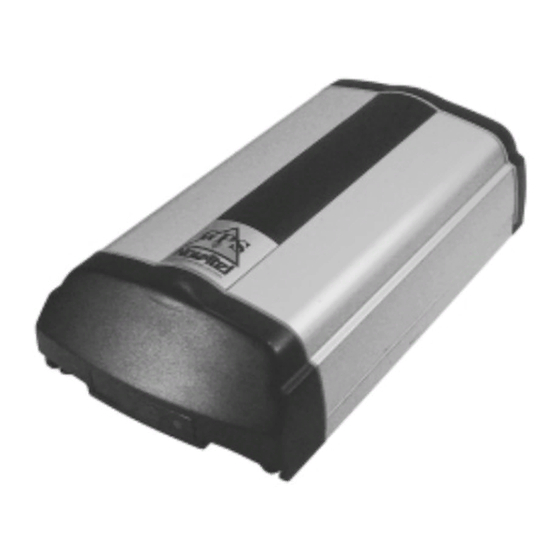
Appendix A - Technical Specifications TECHNICAL SPECIFICATIONS PHOTOGRAPHS Figure 12 GPStation Side View Figure 13 GPStation Front End-cap View GPStation Figure 14 GPStation Rear End-cap View GPStation™ User Manual... - Page 30 5000 m (may operate above this altitude in a controlled environment, however, is not certified as such) Humidity 95% non-condensing VIBRATION The GPStation is not rated for vibration because of its effect on the OCXO. ACCELERATION (DYNAMICS) Acceleration 4 g maximum (sustained tracking) POWER REQUIREMENTS...
- Page 31 ≤ 18,288 m (due to export licensing restrictions) Height Measurements ≤ 515 m/s (due to export licensing restrictions) Velocity Measurements Velocity Accuracy 0.05 m/s (SA off); 0.20 m/s (SA on) Time Accuracy (relative) 50 ns (SA off); 250 ns (SA on) GPStation™ User Manual...
- Page 32 Table 4 contains I/O port pin-out information. The electrical specifications of the strobe signals are as follows: Output Voltage: Standard TTL levels Sink Current: 64 mA Source Current: 15 mA Input Voltage: Standard TTL levels ≤ 5 mA Current: GPStation™ User Manual...
-
Page 34: Appendix B Gpstation Replacement Parts
Appendix B - GPStation Replacement Parts GPStation REPLACEMENT PARTS The following lists describe the replacement parts available for the GPStation system. Should you require assistance or need to order additional components, please contact your NovAtel Customer Service representative. Part Description... -
Page 35: We Would Like To Hear From You
What influenced you to purchase NovAtel GPS products? • Do you have any comments concerning this User Manual? • Are there any new features or products that you would like to see from NovAtel GPS? • Do you have any other comments or suggestions? Your name_______________________________Company___________________________________... - Page 36 NOTES GPStation™ User Manual...
- Page 37 NOTES GPStation™ User Manual...
- Page 38 NovAtel Inc. Recyclable 6732 – 8th Street N.E. Calgary, Alberta, Canada T2E 8M4 GPS Hotline: (403) 295-4900 GPS Fax: (403) 295-4901 Printed in Canada E-mail: gps@novatel.ca on recycled paper Web site: http://www.novatel.ca OM-20000014 – Rev. 1.0 96/10/22 Software Rev. 3.34...
Need help?
Do you have a question about the GPStation and is the answer not in the manual?
Questions and answers