Table of Contents
Advertisement
Quick Links
Download this manual
See also:
User Manual
Advertisement
Table of Contents

Related Manuals for Novatel SPAN-SE


Summary of Contents for Novatel SPAN-SE
- Page 1 SPAN-SE USER MANUAL OM-20000124 Rev 1...
-
Page 2: Proprietary Notice
Information in this document is subject to change without notice and does not represent a commitment on the part of NovAtel Inc. The software described in this document is furnished under a licence agreement or non-disclosure agreement. The software may be used or copied only in accordance with the terms of the agreement. -
Page 3: Table Of Contents
3.5.1 Wheel Sensor Updates Using the Event Input Lines..........49 3.5.2 Wheel Sensor Updates using the iIMU-FSAS IMU ..........50 3.5.3 Wheel Sensor Updates using the WHEELVELOCITY Command......50 3.5.4 Logging Wheel Sensor Data from SPAN-SE............50 3.6 Data Collection for Post Processing ................51 3.7 Status Indicators ......................52... - Page 4 3.10 Synchronizing External Equipment ................57 3.10.1 Configuring a Synchronous Output Pulse............57 3.10.2 Configuring an Input Strobe................58 3.11 SPAN-SE Ethernet Connection ..................59 3.11.1 Configuring for TCP or UDP Operation ..............59 3.11.2 Configuring the Ethernet Connection Settings............60 3.11.3 Configuring Log Requests Destined for the Ethernet Port........60 3.11.4 Connecting to the Ethernet Port .................60...
- Page 5 B.4.34 SETMARK1OFFSET, SETMARK2OFFSET, SETMARK3OFFSET, SETMARK4OFFSET Set Mark offset..............144 B.4.35 SETWHEELPARAMETERS Set wheel parameters ........145 B.4.36 SOFTPOWER Power down the SPAN-SE............147 B.4.37 SPANAUTH Add an authorization code for a new model ........148 B.4.38 SPANMODEL Switch to a previously authorized model........150 B.4.39 UNLOG Remove a log from logging control ............151 B.4.40 UNLOGALL Remove all logs from logging control ..........153...
- Page 6 C.4.49 SPANVALIDMODELS Valid Model Information ..........265 C.4.50 TIME Time Data ....................266 C.4.51 TIMEDWHEELDATA Timed Wheel Data ............268 C.4.52 VEHICLEBODYROTATION Vehicle to SPAN Frame Rotation......269 C.4.53 VERSION Version Information ................270 C.4.54 WHEELSIZE Wheel Size.................273 D Command Prompt Interface D.1 DOS..........................275 SPAN-SE User Manual Rev 1...
- Page 7 F.2 Install the LN-200 Sensor Unit..................284 F.3 Make the Electrical Connections ..................285 F.4 Re-Assemble the SPAN IMU Enclosure.................286 G Frequently Asked Questions H Replacement Parts H.1 SPAN System ........................289 H.2 Accessories and Options ....................289 H.3 Manufacturer’s Part Numbers ..................290 Index SPAN-SE User Manual Rev 1...
- Page 8 IMU Power Cable Pin-Out ....................72 iIMU-FSAS Top/Bottom Dimensions ................74 iIMU-FSAS Enclosure Side Dimensions ...............75 iIMU-FSAS Centre of Navigation ..................76 iIMU Interface Cable Connections with a SPAN-SE .............77 FSAS SPAN-SE Y Adapter Cable ................79 Corrsys Datron WPT .....................80 iMAR iMWS Pre-Installed .....................80 iIMU-FSAS Interface Cable ..................81...
- Page 9 Tables SPAN-SE Compatible Receiver and IMU Models ............24 Receiver Enclosure Back Panel Labels.................29 IMU Power Supply ......................32 Power Button States ......................32 Inertial Solution Status....................43 Solution Parameters ......................46 Positioning Mode LEDs ....................52 I/O 1 Green Cable Connector Pin-Outs .................66 I/O 2 Yellow Cable Connector Pin-Outs ................68 LN-200 IMU Specifications ....................69...
- Page 10 SPAN Receiver Error .....................257 SPAN Receiver Status....................259 Auxiliary 1 Status ......................261 OEMV-3 Status ......................261 OEMV-2 Status ......................261 Status Word ........................264 Event Type........................264 OEMV in SPAN-SE Model Designators.................271 SPAN-SE Model Designators ..................271 Component Types ......................271 VERSION Log: Field Formats..................271 SPAN-SE User Manual Rev 1...
-
Page 11: Software License
However, should NovAtel elect to take such legal proceedings, at NovAtel's request, Licensee shall co-operate reasonably with NovAtel in all legal actions concerning this license of the Software under this Agreement taken against any third party by NovAtel to protect its rights in the Software. - Page 12 NovAtel. This provision shall survive termination of this Agreement howsoever arising. 6. Warranty: NovAtel does not warrant the contents of the Software or that it will be error free. The Software is furnished "AS IS" and without warranty as to the performance or results you may obtain by using the Software.
-
Page 13: Terms And Conditions
NovAtel absolutely. The Buyer shall keep confidential any information expressed or confirmed by NovAtel in writing to be confidential and shall not disclose it without NovAtel's prior consent in SPAN-SE User Manual Rev 1... - Page 14 6. LIMITED WARRANTY AND LIABILITY: Warranty Period: Products - 1 year; Accessories - 90 days (in each case from the date of invoice). NovAtel warrants that during the Warranty Period that (a) the Product will be free from defects in material and workmanship and conform to NovAtel specifications;...
- Page 15 NovAtel shall not be liable to the Buyer by way of indemnity or by reason of any breach of the Order or of statutory duty or by reason of tort (including but not limited to negligence) for any loss of profit, loss of use, loss of production, loss of contracts or for any financing costs or for any indirect or consequential damage whatsoever that may be suffered by the Buyer.
-
Page 16: Warranty Policy
One (1) Year Date of sale shall mean the date of the invoice to the original customer for the product. NovAtel’s responsibility respecting this warranty is solely to product replacement or product repair at an authorized NovAtel location only . - Page 17 Warranty Policy NovAtel warrants that during the Warranty Period that (a) the Product will be free from defects in material and workmanship and conform to NovAtel specifications; and (b) the software will be free from error which materially affect performance. THESE WARRANTIES ARE EXPRESSLY IN...
-
Page 18: Customer Service
Firmware upgrades are accomplished through NovAtel authorized dealers. Contact your local NovAtel dealer first for more information. To locate a dealer in your area or if the problem is not resolved, contact NovAtel Inc. directly using one of the following methods:... -
Page 19: Notices
This device incorporates circuitry to absorb most static discharges . However, severe static shock may cause inaccurate operation of the unit. Use anti-static precautions where possible. This device is a precision instrument. It performs best when handled with care. SPAN-SE User Manual Rev 1... -
Page 20: Foreword
(COM) ports. This manual also describes the INS specific commands and logs. Refer to the OEMV Family Firmware Reference Manual for information on the logs and commands available for the OEMV -3 that is the GNSS engine of your SPAN-SE. Visit www.novatel.com to download any NovAtel product manual. - Page 21 Foreword What’s new in Version 1 of this manual? This manual introduces the SPAN-SE, an enclosure that enhances the powerful OEMV receiver with features that are critical to precision GNSS/INS system integrators such as on-board data logging, Ethernet connectivity, wheel sensor input and scalability for future GNSS advances.
-
Page 22: Introduction
GNSS and the continuity of INS through traditionally difficult GNSS conditions. SPAN-SE is the solution engine of NovAtel’s leading-edge SPAN technology. It provides the user interface to SPAN and outputs raw measurement data or solution data over several communication protocols or to a removable SD Card. -
Page 23: Fundamentals Of Gnss/Ins
IMU itself consists of three accelerometers and 3 gyroscopes (gyros) so that accelerations along specific axis and angular rotations can be measured. Several IMU types are supported and are listed in Table 1, SPAN-SE Compatible Receiver and IMU Models on Page 24 and Table 30, IMU Type on Page 138. -
Page 24: Models And Features
Models and Features All SPAN system receivers are factory configurable for L1/L2 RTK capability and are compatible with an IMU. See Table 1 for firmware model details. Table 1: SPAN-SE Compatible Receiver and IMU Models Model Name Max. Output Rate... - Page 25 Each model has the following standard features: • Rugged shock, water, and dust-resistant enclosure • NovAtel's advanced OEMV L1/L2 GNSS/GLONASS and PAC technology • Four bi-directional COM ports which support data transfer rates of up to 921,600 bits/s • A removable SD Card slot for on-board data collection •...
-
Page 26: Span-Se Installation
SPAN-SE Hardware Description The basic hardware setup consists of a SPAN-SE receiver (see Figure 1 on Page 22) connected to an IMU (see Figure 2 on Page 22), a GNSS antenna and a power supply. For real time differential operation, a communication link between the base and rover(s) is necessary. -
Page 27: Basic Span-Se Set-Up
Figure 3: Basic SPAN-SE Set-Up The sections that follow outline how to set up the system’s parts and cables. See the specifications starting on Page 85 for the NovAtel part numbers of SPAN-SE cables and their pinouts. SPAN-SE User Manual Rev 1... -
Page 28: Sd Memory Card
USB is recommended for logging of high-rate data. Data storage is via a Secure Digital (SD) memory card that you access in the front of the SPAN-SE. See also Section 3.8, The SD Card starting on Page 53. -
Page 29: Span-Se Hardware Installation
Review this section’s hardware set-up subsections and follow the numbered steps, in bold, to install your SPAN system. The example graphics, in the sections that follow, show the connections on the back of a SPAN-SE receiver. SPAN-SE Hardware Installation 2.2.1... -
Page 30: Mount Imu
2.2.3 Connect Interface Cables The SPAN-SE has two circular connectors on the back panel. Each connector has a cable that breaks out the serial ports into DB9 connectors and the input and output event signals to bare wires. Each peripheral signal is identified on the cable with a label. -
Page 31: Connect Power
2.2.4 Connect Power The SPAN-SE receiver requires an input supply voltage between +9 VDC and +28 VDC. The power cable supplied has bare leads that can be connected to an appropriate DC power supply. The receiver has an internal power module that does the following: •... -
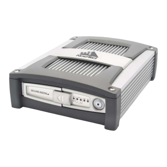
Page 32: Power Button
2.2.5 Power Button The power button on the front of the SPAN-SE, see Figure 6, is managed by software. When the system receives sufficient power, it powers itself on without the need to press the power button. However, the power button is connected directly to the onboard power supply to re-enable the system when it has been automatically shut down and to manually power down the system. - Page 33 Then, refer to your device’s documentation for information on its connectors and cables. The arrow along the cable in the figure indicates a MARKIN pulse from the user device on the right to the SPAN-SE I/O port. SPAN-SE User Manual Rev 1...
-
Page 34: Span-Se Operation
Before operating your SPAN system, ensure that you have followed the installation and setup instructions in Chapter 2, SPAN-SE Installation starting on Page 26. You can use NovAtel’s CDU software to monitor data in real-time. SPAN system output is compatible with post-processing software from NovAtel's Waypoint Products Group. Visit our website at www.novatel.com for details. -
Page 35: The Enclosure Frame
• x-axis–completes the right-handed system (out the right-hand side of the vehicle when facing forward) See the VEHICLEBODYROTATION command on Page 154 for information on entering the rotation into the system and see the RVBCALIBRATE command on Page 127 for information on calculating this rotation. SPAN-SE User Manual Rev 1... -
Page 36: Communicating With The Span System
Figure 9: Vehicle Frame Communicating with the SPAN System Once the receiver is connected to the PC, antenna, and power supply, install NovAtel’s OEMV PC Utilities (CDU and Convert). You can find installation instructions in your receiver’s Quick Start Guide. (Alternatively, you can use a terminal emulator program such as HyperTerminal to communicate with the receiver.) Refer also to the CDU Help file for more details on CDU. - Page 37 Port list. If selecting a network connection, you should have configured an IP address into the receiver prior to connecting, see SPAN-SE Ethernet Connection on Page 59. Select your desired baud rate from the Baud Rate list. If you are logging high-rate data, we recommend using the highest baud rate that your hardware is able to support.
-
Page 38: Ins Window In Cdu
CDU’s SPAN wizard. The INS Configuration/Status section displays the IMU type, IMU Status and local date/time information. The dial is a graphical display of the Roll, Pitch and Azimuth values indicated by an arrow on each axis. SPAN-SE User Manual Rev 1... -
Page 39: Software Configuration
SPAN-SE RTK ROVER CONFIGURATION Command description brackets [ ] represent optional parameters. RTK correction data is input to SPAN-SE using the port labelled OEMV3 on the green cable. The port is configured using the GNSSCARDCONFIG command at the rover as follows: gnsscardconfig [card] [port] rx_type tx_type baud [com control parameters] See Page 105 for a detailed description. -
Page 40: Span Imu Configuration
SPAN Configuration Manually Follow these steps to enable INS as part of the SPAN system using software commands or see SPAN Configuration with CDU on Page 41 to see the preferred method using NovAtel’s Control and Display Unit (CDU) software utility: Issue the SETIMUTYPE command to specify the type of IMU being used. - Page 41 SPAN Configuration with CDU Follow these steps to enable INS as part of the SPAN system using the NovAtel CDU software utility: The CDU screen shots in this manual are from CDU Version 3.3.0.3 and may differ from the current/your CDU version.
- Page 42 Chapter 3 SPAN-SE Operation You need only run the Calibration Wizard if you need to calibrate the lever arm or vehicle to frame angular offsets. It is not required for the SPAN filter to run. SPAN-SE User Manual Rev 1...
-
Page 43: Real-Time Operation
The INS filter is in navigation mode, but not enough vehicle dynamics have been experienced for the system to be within specifications. 1. See also the Frequently Asked Question appendix, question #8 on Page 288 SPAN-SE User Manual Rev 1... -
Page 44: Configuration For Alignment
The inertial alignment routine starts and the INS Status field reports INS_ALIGNING. Alignment is complete and the INS Status field changes to INS_ALIGNMENT_COMPLETE. The system transitions to navigation mode. The solution is refined using updates from GNSS. Once the system is operating within specifica- SPAN-SE User Manual Rev 1... - Page 45 VEHICLEBODYROTATION 0 0 0 Alternatively, solve the vehicle to IMU frame angular offsets using the RVBCALIBRATE routine. See also Section 3.4.7, Vehicle to SPAN frame Angular Offsets Calibration Routine starting on Page 48. SPAN-SE User Manual Rev 1...
-
Page 46: Navigation Mode
INSVEL or INSVELS INSSPD or INSSPDS INSPVA or INSPVAS Attitude INSATT or INSATTS INSPVA or INSPVAS Solution Uncertainty INSCOV or INSCOVS Note that the position, velocity and attitude are available together in the INSPVA and INSPVAS logs. SPAN-SE User Manual Rev 1... -
Page 47: Lever Arm Calibration Routine
The BESTPOS position log can be logged at rates up to 20 Hz directly from the OEMV port, but is available at 1 Hz or 5 Hz from any SPAN-SE port. Other GNSS logs (RANGE, PSRPOS, and so on) can be logged up to 20 Hz from the SPAN ports. The BESTGPSPOS log is available from SPAN-SE only, at 1 Hz or 5 Hz. -
Page 48: Vehicle To Span Frame Angular Offsets Calibration Routine
Avoid driving on a surface with a constant, non-zero, slope to prevent biases in the computed angles. Vehicle speed must be greater than 5 m/s (18 km/hr) for the calibration to complete. SPAN-SE User Manual Rev 1... -
Page 49: Span Wheel Sensor Configuration
Specific details on the three methods of wheel sensor input are described below. 3.5.1 Wheel Sensor Updates Using the Event Input Lines The event input lines in SPAN-SE can be configured to accept a wheel sensor signal directly. Any of SPAN-SE User Manual Rev 1... -
Page 50: Wheel Sensor Updates Using The Iimu-Fsas Imu
SPAN GNSS/INS filter. To connect your wheel sensor to the SPAN-SE event input line, connect Signal A from the wheel sensor to one of the event input lines available on the I/O 2 yellow cable (see I/O 2 Yellow Cable on Page 67). -
Page 51: Data Collection For Post Processing
GLORAWEPHEMB ONNEW • GLOEPHEMERISB ONCHANGED • RAWIMUSB ONNEW • BESTLEVERARMB ONNEW Post processing is performed through the Waypoint Inertial Explorer software package available from from NovAtel's Waypoint Products Group. Visit our website at www.novatel.com for details. SPAN-SE User Manual Rev 1... -
Page 52: Status Indicators
SPAN-SE Operation Status Indicators LED indicators on the front of the SPAN-SE, see Figure 10 below, provide the status of the receiver. Table 7 details the LED states, which are solid unless otherwise indicated as blinking. They represent these categories: Power, SD Card, OEMV-2 Card (which is not included in every SPAN-SE system), OEMV-3 Card, IMU (which indicates the status of the raw data received from the IMU) and INS (which indicates the status of the GNSS/INS solution computed by the SPAN-SE). -
Page 53: The Sd Card
Chapter 3 The SD Card Data commands and logs can be recorded from the SPAN-SE to a removable SD Card. The need for a companion handheld data logger is avoided and continuous user interaction is not required, since the SPAN-SE is capable of logging data according to pre-configured parameters without any user intervention. -
Page 54: Prepare The Card
SPAN-SE Operation 3.9.2 Prepare the Card To prepare the SD Card in the SPAN-SE for data logging: Connect to the receiver through the serial, USB or Ethernet ports. If necessary, format the card using the command FORMAT SD. During the format process, the SD LED flashes alternating green and orange. -
Page 55: Select Logs To Send To The Sd Card
Page 117. Once a list of logs has been specified for logging, press the Log button, on the SPAN-SE, once, to start the logging into an auto-named logging file in the current working directory. Press the button a second time to stop the logging and close the file. -
Page 56: Auto-Logging On Start-Up
Remove the card from the receiver and read the data using a PC SD Card reader. Use the File Transfer Protocol (FTP) functionality built into the SPAN-SE: • The FTP functionality is available over the Ethernet port on the receiver. -
Page 57: Synchronizing External Equipment
SPAN-SE Operation Chapter 3 Use the NovAtel Explorer inside CDU to download the files from the SD Card over any of the SPAN-SE ports connected to a PC. While all ports are supported, for the fastest transfer, use the USB connection. -
Page 58: Configuring An Input Strobe
3.10.2 Configuring an Input Strobe SPAN-SE has four available input strobes. The input strobes apply an accurate GPS time to the rising, or falling, edge of an input pulse called an event. For each event, an accurate position, velocity or attitude solution is also available. -
Page 59: Span-Se Ethernet Connection
Ethernet, Port 3000 can be used for both Transmission Control Protocol (TCP) and User Datagram Protocol (UDP) traffic, but not simultaneously. SPAN-SE uses a static IP address. Dynamic Host Configuration Protocol (DHCP) is a protocol for automating the configuration of computers that use TCP/IP. There is no DHCP support at this time. -
Page 60: Configuring The Ethernet Connection Settings
For details on the FTP functionality of the Ethernet port, see the FTP DOS command on Page 89. To connect the SPAN-SE directly to your PC Ethernet port (not through a network), follow these steps: Connect you PC Ethernet port to the SPAN-SE Ethernet port using an Ethernet cross-over cable. -
Page 61: A Technical Specifications
Appendix A Technical Specifications This appendix details the technical specifications of the IMUs and the SPAN-SE receiver. Refer to your SPAN system enclosure (for example, ProPak-V3) manual (OEMV Family Installation and Operation User Manual) for more information on its technical specifications, performance and cables. - Page 62 IEC 60529 IPX6 Dust IEC 68-2-27, 60 g Shock (non-operating) RTCA D0-160D, curve C Vibration (random) IEC 68-2-6 Vibration (sinusoidal) FCC Part 15, Class B Emissions EN 55022, Class B Emissions EN 55024 Immunity EN 60950-1 Safety SPAN-SE User Manual Rev 1...
- Page 63 Appendix A DIMENSIONS 75.697 SCALE 1.000 247.259 199.138 a. All dimensions are in millimeters, please use the Unit Conversion section of GNSS+: A Reference Guide, available from our website at www.novatel.com for conversion to imperial measurements. SPAN-SE User Manual Rev 1...
-
Page 64: Span-Se Power Cable
A.1.1.1 Power Adapter Cable (NovAtel part number 01018135) The power adapter cable supplied with the SPAN-SE, see Figure 13, provides a means for supplying +9 to +28 V DC while operating in the field. Input is provided through the bare wire power outlets. The exposed wires (red and orange for positive, brown and black for negative) can then be tied to a supply capable of at least 10 W for a single antenna or 12 W for dual antennas. -
Page 65: Span-Se I/O 1 Green Cable
A.1.1.2 I/O 1 Green Cable (NovAtel part number 01018134) This cable, supplied with the SPAN-SE, see Figure 14, provides a means of connecting with communications and I/O devices. The cable is equipped with a 30-pin connector at the receiver end plus four DB-9 connectors at the other end, one for each serial port. -
Page 66: I/O 1 Green Cable Connector Pin-Outs
RXD_V2 OEMV2 TXD_V2 OEMV2 OEMV2 RTS_V2 OEMV2 CTS_V2 OEMV2 RXD_V3 OEMV3 TXD_V3 OEMV3 VDC OUT OEMV3 OEMV3 RTS_V3 OEMV3 CTS_V3 OEMV3 a. Refer to connector numbers, P1 through P6 in Figure 14 on Page 65 SPAN-SE User Manual Rev 1... -
Page 67: Span-Se I/O 2 Yellow Cable
A.1.1.3 I/O 2 Yellow Cable (NovAtel part number 01018133) This cable, supplied with the SPAN-SE, see Figure 15, provides a means of connecting with communications and I/O devices. The cable is equipped with a 30-pin connector at the receiver end plus three DB-9 connectors at the other end, each connected to a serial port. -
Page 68: I/O 2 Yellow Cable Connector Pin-Outs
COM1 CTS1 COM1 EVENT-OUT 4 RXD_IMU TXD_IMU RTS_IMU CTS_IMU a. Refer to connectors P1, P2, P7 and P10, and to the bare wires in Detail A and Detail B, in Figure 15 on Page 67 SPAN-SE User Manual Rev 1... -
Page 69: Inertial Measurement Units (Imus)
~3 kg (6.6 lb.) MECHANICAL DRAWINGS 13.3 143.7 4 PLCS. 76.8 76.2 Enclosure Center 82.4 134.6 Navigation Center SCALE 0.800 70.7 Navigation Center R92.9 76.3 Enclosure Center Figure 16: LN-200 IMU Enclosure Top/Bottom Dimensions and Centre of Navigation SPAN-SE User Manual Rev 1... - Page 70 Appendix A Technical Specifications SPAN-SE User Manual Rev 1...
-
Page 71: Imu Interface Cable Pin-Out (Propak-V3)
A.2.1.1 LN-200 IMU Interface Cable NovAtel’s part number for the LN-200 IMU interface cable is 01017375 (Figures 18 and 19 below). The IMU interface cable supplied enables input and output between the IMU and the receiver. Figure 18: LN-200 Interface Cable... -
Page 72: Imu Power Cable Pin-Out
A.2.1.2 LN-200 IMU Power Adapter Cable The power adapter cable, NovAtel part number 01017821, supplied with the LN-200 provides a convenient means for supplying +12 VDC while operating from a 12V source. Figure 20 shows the cable and Figure 21 the wiring diagram of the 12V adapter. - Page 73 -30C to +60C (-22F to 140F) Storage -45C to +80C (-49F to 176F) Humidity 95% non-condensing a. For replacement connectors on the interface or power cables, see Section H.3, Manufacturer’s Part Numbers on Page 290. SPAN-SE User Manual Rev 1...
-
Page 74: Iimu-Fsas
128 mm x 128 mm x 104 mm (5.04” x 5.04” x 4.09”) IMU Weight 2.1 kg (4.63 lb.) MECHANICAL DRAWINGS 35.5 Figure 22: iIMU-FSAS Top/Bottom Dimensions a. See Figure 24 on Page 76 for the centre of navigation dimensions b. Dimensions are in mm. SPAN-SE User Manual Rev 1... -
Page 75: Iimu-Fsas Enclosure Side Dimensions
Technical Specifications Appendix A Figure 23: iIMU-FSAS Enclosure Side Dimensions SPAN-SE User Manual Rev 1... -
Page 76: Iimu-Fsas Centre Of Navigation
Appendix A Technical Specifications Figure 24: iIMU-FSAS Centre of Navigation SPAN-SE User Manual Rev 1... -
Page 77: Iimu Interface Cable Connections With A Span-Se
Page 78 and Figure 29, iIMU-FSAS Interface Cable on Page 81). See also Section A.2.2.2, iIMU- FSAS Odometer Cabling on Page 79 if applicable. To talk to the SPAN-SE with the iIMU-FSAS interface cable, a FSAS SPAN-SE Y Adapter cable is needed. Please see Table 13 on Page 79 for cable pin-out information. -
Page 78: Imu Interface Cable Pin-Out
Twisted pair; serial data in / RS- 422(-) SW_ON_ Connected to Pin 3; switch IMU signal ON/OFF (voltage applied = ON) +4 to +34 V SW_ON_ Connected to Pin 1; ground for IMU signal ON a. RS-422 compatible SPAN-SE User Manual Rev 1... -
Page 79: Fsas Span-Se Y Adapter Cable
Technical Specifications Appendix A Table 13: FSAS SPAN-SE Y Adapter Cable Pin-Out DB-9 Male to FSAS DB-9 Female to DB-9 Female to COM 3 Cable FSAS I/O Cable Function SPAN-SE Cable Description (F2 in Figure 26) (M1 in Figure 26) -
Page 80: Corrsys Datron Wpt
The NovAtel IMU interface cable, with ODO, is the same as that in Section A.2.2.1 but with some of the reserved pins having odometer uses. It still provides power to the IMU from an external source, and enables input and output between the receiver and IMU. -
Page 81: Iimu-Fsas Interface Cable
WPT needs power to operate (+10 to +30 V). Solder the shield on the WPT cable to the female DB9 housing. b. This modification is for the Corrsys Datron WPT 8-pin M12-plug cable number 14865. Figure 29: iIMU-FSAS Interface Cable SPAN-SE User Manual Rev 1... - Page 82 14.8 W (typical) Data Connector MIL-C-38999-III Power Connector MIL-C-38999-III (same as data connector) IMU Interface RS-422 ENVIRONMENTAL IMU-FSAS) Temperature Operating -40C to +71C (-40F to 160F) Storage -40C to +85C (-40F to 185F) Humidity 95% non-condensing SPAN-SE User Manual Rev 1...
-
Page 83: Hg1700 Imu
Navigation, shown on the HG1700 label, for the internal IMU is the same as the enclosure’s center. The enclosure center measurements are labelled as: IMU Enclosure Center in this figure. Figure 30: HG1700 Top/Bottom Dimensions SPAN-SE User Manual Rev 1... - Page 84 Appendix A Technical Specifications SPAN-SE User Manual Rev 1...
- Page 85 -30C to +60C (-22F to 140F) Storage -45C to +80C (-49F to 176F) Humidity 95% non-condensing a. For replacement connectors on the interface and power cables, see Section H.3, Manufacturer’s Part Numbers on Page 290. SPAN-SE User Manual Rev 1...
-
Page 86: B Commands
00000000 2304B3F1 B.2 Using a Command as a Log All NovAtel commands may be used for data input, as normal, or used to request data output (a unique OEMV Family feature). INS-specific commands may be in Abbreviated ASCII, ASCII, or Binary format. -
Page 87: Dos Commands
The BESTPOS position log can be logged at rates up to 20 Hz directly from the OEMV port, but is available at 1 Hz or 5 Hz from any SPAN-SE port. Other GNSS logs (RANGE, PSRPOS, and so on) can be logged up to 20 Hz from the SPAN ports. The BESTGPSPOS log is available from SPAN-SE only, at 1 Hz or 5 Hz. -
Page 88: Dir - Show Directory
(SD = default) Path Null terminated string B.3.5 RMDIR - Remove Directory Command: RMDIR (Message ID = 1058) Parameter Values Mass Storage Device Enum, see Table 16 on Page 87 (SD = default) Path Null terminated string SPAN-SE User Manual Rev 1... -
Page 89: Pwd - Present Working Directory
(SD = default) B.3.7 The SPAN-SE has a built-in FTP server to simplify retrieving data from the SD Card. After the IP information has been set, using the IFCONFIG command, any FTP client can connect to the SPAN- SE on port 21. The FTP server allows basic file manipulation and directory browsing but files cannot be uploaded to the SD Card at this time. -
Page 90: Applyvehiclebodyrotation Enable Vehicle To Body Rotation
ASCII, ASCII or binary, respectively. switch Disable Enable/disable vehicle body Enum rotation using values entered Enable in the vehiclebodyrotation command. default = disable Abbreviated ASCII Example: APPLYVEHICLEBODYROTATION ENABLE SPAN-SE User Manual Rev 1... -
Page 91: Assignlband Set L-Band Satellite Communication Parameters
The factory parameter default is ASSIGNLBAND IDLE. 1. In addition to a NovAtel receiver with L-band capability, a subscription to the OmniSTAR, or use of the free CDGPS, service is required. Contact NovAtel for details, see Page 18. -
Page 92: L-Band Mode
2. Refer also to the L-band Tracking and Data Output with GPS application note available on our website as APN-043 at http://www.novatel.com/support/applicationnotes.htm. SPAN-SE User Manual Rev 1... - Page 93 See also Beam 1525000000 to Frequencies on Page 93. 1560000000 (default = 1536782 if the mode is OMNISTAR) baud 300, 600, 1200, Data rate for communication Ulong 2400 or 4800 with L-band satellite (default = 1200) SPAN-SE User Manual Rev 1...
-
Page 94: Com Port Configuration Control
Return the current port to its default settings • Set the interface mode to NovAtel for both input and output (see the GNSSCARDCONFIG command on Page 105) 1. The COMCONTROL command, see Page 97, may conflict with handshaking of the selected COM port. -
Page 95: Com Serial Port Identifiers
COM4 COM Port 4 ETH1 10/100 Ethernet Table 19: Parity Binary ASCII Description No parity (default) Even parity Odd parity Table 20: Handshaking Binary ASCII Description No handshaking (default) XON/XOFF software handshaking CTS/RTS hardware handshaking SPAN-SE User Manual Rev 1... - Page 96 (default = 1) handshake See Table 20 on Page 95 Handshaking Enum H+20 echo No echo Enum H+24 (default) Transmit any input characters as they are received break Disable break detection Enum H+28 Enable break detection (default) SPAN-SE User Manual Rev 1...
-
Page 97: Comcontrol Control The Rs232 Hardware Control Lines
PC computer by using the RTS or DTR lines. The accuracy of controlling the COM control signals is better than 900 s. As a SPAN-SE user, you have access to 3 event out lines that can provide precise PPS output. The other modes are typically used to control custom peripheral devices. -
Page 98: Span-Se Com Port Values
Appendix B Commands Table 22: SPAN-SE COM Port Values Binary ASCII COM1 COM2 COM3 THISPORT FILE USB1 COM4 ETH1 SPAN-SE User Manual Rev 1... - Page 99 Not for TX. PULSEPPSHIGH Pulses line high for 1 ms at time of a 1PPS event mode RS232 RS-232 mode Enum H+12 RS422 RS-422 mode Used only for ETH1 and USB1 information SPAN-SE User Manual Rev 1...
-
Page 100: Comvout Turn Power To The Ports On Or Off
This field contains the command name or the message header depending on whether the command is abbreviated ASCII, ASCII or binary, respectively. switch The state of the output power Enum lines. Abbreviated ASCII Example: COMVOUT ON SPAN-SE User Manual Rev 1... -
Page 101: Eventincontrol Control Mark Input Properties
If Field #3 is EVENT: Ulong H+16 Time guard in milliseconds: default = 4 minimum = 4 maximum = 3 599 999 If Field #3 is COUNT: This field is not used Abbreviated ASCII Example: EVENTINCONTROL MARK1 COUNT SPAN-SE User Manual Rev 1... -
Page 102: Eventoutcontrol Control Pps Signal Properties
= 999 999 000 not- Not-active period of the Event Ulong H+16 active Out signal in nanoseconds: period default = 500 000 000 minimum = 1000 maximum = 999 999 000 Abbreviated ASCII Example: EVENTOUTCONTROL MARK3 ENABLE SPAN-SE User Manual Rev 1... -
Page 103: Format The Sd Card
Commands Appendix B B.4.8 FORMAT Format the SD Card This command allows you to format the SC card in the SPAN-SE. Abbreviated ASCII Syntax: Message ID: 1057 FORMAT device [volume] Field ASCII Binary Binary Binary Binary Field Description Type Value... -
Page 104: Freset Factory Reset
The receiver is forced to hardware reset. When the SPAN-SE receives a FRESET command, it is also passed to the OEMV-3 but without any parameters. Therefore the OEMV-3 only does a full reset. SPAN-SE can do a partial reset of some of its fields. -
Page 105: Gnsscardconfig Gnss Port Configuration
Use this command to configure both the interface mode and COM port mode on an internal GNSS card from a SPAN-SE receiver port. Do this from a [COM1], [COM2], [COM3], [COM4], [ETH1], or [USB1] prompt. The GNSSCARDCONFIG command is especially useful for configuring RTK because the OEMV3 COM1 port is used for RTK correction input data. -
Page 106: Serial Port Interface Modes
Appendix B Commands Abbreviated ASCII Example: GNSSCARDCONFIG CARD1 COM1 RTCA NOVATEL ON 57600 N 8 1 N OFF ON Table 24: Serial Port Interface Modes Binary Value ASCII Mode Name Description NONE The port accepts/generates nothing NOVATEL The port accepts/generates NovAtel commands and... -
Page 107: Ifconfig Set Ip Information
Commands Appendix B B.4.11 IFCONFIG Set IP information Use this command to configure Internet Protocol (IP) information. See also Section 3.11, SPAN-SE Ethernet Connection on Page 59. Abbreviated ASCII Syntax: Message ID: 1059 IFCONFIG IP mask gateway Field ASCII Binary... -
Page 108: Inscommand Ins Control Command
ASCII, ASCII or binary, respectively. action RESET Resets the GNSS/INS Enum alignment and restarts the alignment initialization. DISABLE Disables INS positioning. ENABLE Enables INS positioning where alignment initialization starts again. (default) Abbreviated ASCII Example: INSCOMMAND ENABLE SPAN-SE User Manual Rev 1... -
Page 109: Inszupt Request Zero Velocity Update
This command allows you to manually perform a Zero Velocity Update (ZUPT), that is, to update the receiver when the system has stopped. NovAtel’s SPAN Technology System does ZUPTs automatically. It is not necessary to use this command under normal circumstances. -
Page 110: Leverarmcalibrate Ins Calibration Command
ASCII, ASCII or binary, respectively. switch Offset along the IMU X axis Enum ON (default) maxtime 0 - 1000 Maximum calibration time (s) Double maxstd 0.02 – 0.5 Maximum offset uncertainty (m) Double H+12 SPAN-SE User Manual Rev 1... - Page 111 <= 0.05 m in each direction (x, y, z), whichever happens first. Abbreviated ASCII Example 3: LEVERARMCALIBRATE OFF 0 This command stops the calibration. The current estimate, when the command was received, is output in the BESTLEVERARM log, and used in the SPAN computations. SPAN-SE User Manual Rev 1...
-
Page 112: Log Request Logs From The Receiver
The [port] parameter is optional. If [port] is not specified, [port] is defaulted to the port that the command was received on. 1. SPAN-SE users can request up to 25 GNSS only logs (that is, logs generated on the internal OEMV-3), and up to 30 SPAN-specific logs, provided the requested data amount is less than the effective baud rate of the communication port logging the data. - Page 113 UNLOGALL command. To send a log only one time, the trigger option can be ignored. Abbreviated ASCII Example 2: LOG COM1 PSRPOS ONCE NOHOLD See Section Section B.1, Command Formats on Page 86 for additional examples. SPAN-SE User Manual Rev 1...
- Page 114 Valid values for the high rate Log period (for ONTIME Double H+12 logging are 0.05, 0.1, 0.2, 0.25 trigger) in seconds and 0.5. For logging slower than 1Hz any integer value is accepted. Continued on Page 115 SPAN-SE User Manual Rev 1...
- Page 115 2. See Appendix A in the OEMV Family Installation and Operation User Manual for the maximum raw measurement rate to calculate the minimum period. If the value entered is lower than the minimum measurement period, the value is ignored and the minimum period is used. SPAN-SE User Manual Rev 1...
- Page 116 60 and the offset to 1 (default = 0) hold NOHOLD Allow log to be removed by the UNLOGALL command Enum (default) HOLD Prevent log from being removed by the UNLOGALL command SPAN-SE User Manual Rev 1...
-
Page 117: Logfile Log Data To A File On The Sd Card
= SD filename Filename where filenames have a Char[12] maximum 12 character limit. default = SPAN_#.log where # is the next number in the list starting at 0 Abbreviated ASCII Example: LOGFILE OPEN SD SITE1.GPS SPAN-SE User Manual Rev 1... -
Page 118: Nmeatalker Set The Nmea Talker Id
Offset NMEA- This field contains the command TALKER name or the message header header depending on whether the command is abbreviated ASCII, ASCII or binary, respectively. GNSS (GP) only Enum AUTO GNSS and/or Inertial (IN) SPAN-SE User Manual Rev 1... -
Page 119: Psrdiffsource Set The Pseudorange Correction Source
RTKSOURCE command on Page 125. 1. To use L-band differential corrections, an L-band receiver and a subscription to the OmniSTAR, or use of the free CDGPS, service are required. Contact NovAtel for details, see Page 18. 2. Since several errors affecting signal transmission are nearly the same for two receivers near each other on the ground, a base at a known location can monitor the errors and generate corrections for the rover to use. -
Page 120: Dgps Type
AUTO RTCA message has preference over an L-band message. In the RTKSOURCE command, AUTO means that both the NovAtel RTK filter and the OmniSTAR HP/XP filter (if authorized) are enabled. The NovAtel RTK filter selects the first received RTCM, RTCA, RTCMV3 or CMR message. - Page 121 1. If you choose ANY, the receiver ignores the ID string. Specify a Type when you are using base station IDs. 2. In the binary log case, an additional 3 bytes of padding are added to maintain 4-byte alignment SPAN-SE User Manual Rev 1...
-
Page 122: Reset Perform A Hardware Reset
Offset RESET header This field contains the command name or the message header depending on whether the command is abbreviated ASCII, ASCII or binary, respectively. delay Seconds to wait before resetting. Ulong (default = 0) SPAN-SE User Manual Rev 1... -
Page 123: Rtkcommand Reset Or Set The Rtk Filter To Its Defaults
Offset RTKCOMMAND This field contains the header command name or the message header depending on whether the command is abbreviated ASCII, ASCII or binary, respectively. type USE_DEFAULTS Reset to defaults Enum RESET Reset RTK algorithm SPAN-SE User Manual Rev 1... -
Page 124: Rtkdynamics Set The Rtk Dynamics Mode
Bytes Offset RTKDYNAMICS This field contains the command header name or the message header depending on whether the command is abbreviated ASCII, ASCII or binary, respectively. mode See Table 27 Set the dynamics mode Enum SPAN-SE User Manual Rev 1... -
Page 125: Rtksource Set The Rtk Correction Source
To use OmniSTAR HP/XP differential corrections, a NovAtel receiver with L-band capability and a subscription to the OmniSTAR service are required. Contact NovAtel for details. Contact information may be found on the back of this manual or you can refer to the Customer Service section in the OEMV Family Installation and Operation User Manual. - Page 126 1. If you choose ANY, the receiver ignores the ID string. Specify a Type when you are using base station IDs. 2. In the binary log case, an additional 3 bytes of padding are added to maintain 4-byte alignment. SPAN-SE User Manual Rev 1...
-
Page 127: Rvbcalibrate Vehicle To Body Rotation Control
Header command name or the message header depending on whether the command is abbreviated ASCII, ASCII or binary, respectively. RESET Switch Control the vehicle/ ENUM body rotation DISABLE computation ENABLE Abbreviated ASCII Example: RVBCALIBRATE RESET SPAN-SE User Manual Rev 1... -
Page 128: Saveconfig Save Current Configuration In Nvm
If you are using this command in CDU, ensure that you have all windows other than the Console window closed. Otherwise, log commands used for the various windows are saved as well. This will result in unnecessary data being logged. Abbreviated ASCII Syntax: Message ID: 19 SAVECONFIG SPAN-SE User Manual Rev 1... -
Page 129: Sbascontrol Set Sbas Test Mode And Prn
Don’t use any SBAS satellites AUTO Automatically determine satellite system to use (default) Use any and all SBAS satellites found WAAS Use only WAAS satellites EGNOS Use only EGNOS satellites MSAS Use only MSAS satellites SPAN-SE User Manual Rev 1... - Page 130 0 messages as they are intended (as do not use) (default) ZEROTOTWO Receiver interprets Type 0 messages as Type 2 messages IGNOREZERO Receiver ignores the usual interpretation of Type 0 messages (as do not use) and continues SPAN-SE User Manual Rev 1...
-
Page 131: Setautologging Start Sd Card Logging At Boot-Up
This field contains the command name or the message header depending on whether the command is abbreviated ASCII, ASCII or binary, respectively. switch Enable or disable auto loggin g Enum on boot-up Abbreviated ASCII Example: SETAUTOLOGGING ON SPAN-SE User Manual Rev 1... -
Page 132: Setethprotocol Set Eth1 Protocol
Commands B.4.27 SETETHPROTOCOL Set Eth1 Protocol The SPAN-SE has a 10/100 RJ-45 Ethernet port, which has a MAC address hard coded into flash and user-configurable IP information. Port 3000 can be used for both TCP and UDP traffic but not simultaneously. -
Page 133: Setimuorientation Set Imu Orientation
IMU, see the IMU choices and their technical specifications starting on Page 61. The example from the LN-200 is shown in Figure 32. Figure 32: Frame of Reference SPAN-SE User Manual Rev 1... - Page 134 IMU X axis is pointing DOWN IMU Y axis is pointing UP IMU Y axis is pointing DOWN IMU Z axis is pointing UP IMU Z axis is pointing DOWN Abbreviated ASCII Example: SETIMUORIENTATION 1 SPAN-SE User Manual Rev 1...
-
Page 135: Full Mapping Definitions
Commands Appendix B Table 29: Full Mapping Definitions SPAN-SE User Manual Rev 1... -
Page 136: Setimutoantoffset Set Imu To Antenna Offset
0.01 m) 0 to +1 Uncertainty in z (m) Double H+40 (Defaults to 10% of the z offset to a minimum of 0.01 m) Abbreviated ASCII Example: SETIMUTOANTOFFSET 0.54 0.32 1.20 0.03 0.03 0.05 SPAN-SE User Manual Rev 1... -
Page 137: Setimutype Set Imu Type
This field contains the Header command name or the message header depending on whether the command is abbreviated ASCII, ASCII or binary, respectively. Switch See Table 30, IMU IMU Type ENUM Type, on Page 138 SPAN-SE User Manual Rev 1... -
Page 138: Imu Type
Honeywell HG1700 AG11/AG58 Reserved IMU_HG1700_AG17 Honeywell HG1700 AG17/AG62 Reserved IMU_LN200 Litton LN-200 (200 Hz model) IMU_LN200_400HZ Litton LN-200 (400 Hz model) IMU_IMAR_FSAS iMAR iIMU-FSAS IMU_HG1700_AG58 Honeywell HG1700 AG58 IMU_HG1700_AG62 Honeywell HG1700 AG62 Abbreviated ASCII Example: SETIMUTYPE IMU_IMAR_FSAS SPAN-SE User Manual Rev 1... -
Page 139: Setinitattitude Set Initial Attitude Of Span In Degrees
IMU mounted with the z axis not pointing up. Then use the tables in the SETIMURIENTATION command, on Pages 134-135, to determine the azimuth axis that SPAN is using. Abbreviated ASCII Syntax: Message ID: 862 SETINITATTITUDE pitch roll azimuth pitchSTD rollSTD azSTD SPAN-SE User Manual Rev 1... - Page 140 This means that the SPAN system is very close to level with respect to the local gravity field. The azimuth is 90 degrees (see the SETINITAZIMUTH example on Page 141), also with a 5 degrees standard deviation. SPAN-SE User Manual Rev 1...
-
Page 141: Setinitazimuth Set Initial Azimuth And Standard Deviation
ASCII, ASCII or binary, respectively. azimuth -360 to +360 Input azimuth angle in degrees Double 0.000278 to 180 Input azimuth standard deviation azSTD Double angle in degrees SPAN-SE User Manual Rev 1... - Page 142 SPAN system with the positive Z axis (as marked on the enclosure) in a direction that is not up, please refer to the SETIMUORIENTATION command to determine the SPAN computation frame axes mapping that SPAN automatically applies. SPAN-SE User Manual Rev 1...
-
Page 143: Setinsoffset Set Ins Offset
Y offset ± 100 Offset along the IMU enclosure Double frame Y axis (m) Z offset ± 100 Offset along the IMU enclosure Double H+16 frame Z axis (m) Abbreviated ASCII Example: SETINSOFFSET 0.15 0.15 0.25 SPAN-SE User Manual Rev 1... -
Page 144: Setmark1Offset, Setmark2Offset, Setmark3Offset
Roll offset for Mark (degrees) Double H+24 offset ± 360 Pitch offset for Mark (degrees) Double H+32 offset ± 360 Azimuth offset for Mark (degrees) Double H+40 Abbreviated ASCII Example: SETMARK1OFFSET -0.324 0.106 1.325 0 0 0 SPAN-SE User Manual Rev 1... -
Page 145: Setwheelparameters Set Wheel Parameters
SETWHEELPARAMETERS 1000 2.03 0.002 If you have an external wheel sensor that will be connected to an EVENT line on the SPAN-SE, then the SETWHEELPARAMETERS command must be sent in order to select which MARK to use The wheel parameters must also be specified here as the default values will not be used. -
Page 146: Setwheelparameters Input
Fields 2, 3 and 4 do not have to ‘add up’. Field 4 is used to weight the wheel sensor measurement. Fields 2 and 3 are used with the estimated scale factor to determine the distance travelled. SPAN-SE User Manual Rev 1... -
Page 147: Softpower Power Down The Span-Se
B.4.36 SOFTPOWER Power down the SPAN-SE Use the SOFTPOWER command to power down the SPAN-SE. This command is meant for automated setups where the user may not be able to physically touch the SPAN-SE but needs to shut the system down. -
Page 148: Spanauth Add An Authorization Code For A New Model
OEMV Family Firmware Reference Manual. We recommend that you contact NovAtel Customer Service for assistance in doing this, see Page 18 or Note #2 below. 1. Authorization codes are firmware version specific. If the receiver firmware is updated, it is necessary to acquire new SPAN authorization codes for the required models. - Page 149 [max. 16] able date Numeric Null Expiry date entered as String Vari- Vari-able terminated yymmdd in decimal. [max. 7] able 1. In the binary log case, additional bytes of padding are added to maintain 4-byte alignment SPAN-SE User Manual Rev 1...
-
Page 150: Spanmodel Switch To A Previously Authorized Model
Max 16 character SPAN model name String Variable Variable null-terminated [max. 16] string (including the null) Reserved Ulong Variable 1. In the binary log case, additional bytes of padding are added to maintain 4-byte alignment SPAN-SE User Manual Rev 1... -
Page 151: Unlog Remove A Log From Logging Control
Char type Bits 5-6 = Format 00 = Binary 01 = ASCII 10 = Abbreviated ASCII, NMEA 11 = Reserved Bit 7 = Response Bit 0 = Original Message 1 = Response Message Reserved Char SPAN-SE User Manual Rev 1... - Page 152 ASCII, ASCII or binary, respectively. port See Table 18, COM Serial Port Port to which log is being Enum Identifiers, on Page 95 sent (default = THISPORT) message Message Name Message Name of log to ULong be disabled SPAN-SE User Manual Rev 1...
-
Page 153: Unlogall Remove All Logs From Logging Control
Port to clear Enum (default = ALL_PORTS) Serial Port Identifiers, on Page 95 held FALSE Does not remove logs with the Enum HOLD parameter (default) TRUE Removes previously held logs, even those with the HOLD parameter SPAN-SE User Manual Rev 1... -
Page 154: Vehiclebodyrotation Vehicle To Span Frame Rotation
To apply the vehicle to body rotation angles to the output attitude in the INSPVA or INSATT logs, the APPLYVEHICLEBODYROTATION command needs to be enabled, please refer to Section B.4.1, APPLYVEHICLEBODYROTATION Enable vehicle to body rotation starting on Page 90. SPAN-SE User Manual Rev 1... - Page 155 32-bit CRC H+48 [CR][LF] Sentence Terminator (ASCII only) Refer also to our application note on Vehicle to Body Rotations, NovAtel part number APN-037 (available on our website at http://www.novatel.com/support/applicationnotes.htm). Abbreviated ASCII Example: VEHICLEBODYROTATION 0 0 90 0 0 5 SPAN-SE User Manual Rev 1...
-
Page 156: Wheelvelocity Wheel Velocity For Ins Augmentation
H+20 Cumulative number of ticks/s Ulong Refer also to our application note on Using a Wheel Sensor with SPAN, NovAtel part number APN- 036 (available on our website at http://www.novatel.com/support/applicationnotes.htm). Abbreviated ASCII Example: WHEELVELOCITY 123 8 10 0 0 0 0 40... -
Page 157: C Data Logs
2. The BESTPOS position log can be logged at rates up to 20 Hz directly from the OEMV port, but is available at 1 Hz or 5 Hz from any SPAN-SE port. Other GNSS logs (RANGE, PSRPOS, and so on) can be logged up to 20 Hz from the SPAN ports. The BESTGPSPOS log is available from SPAN-SE only, at 1 Hz or 5 Hz. -
Page 158: Log Type Triggers
1. A SPAN-SE user can request up to 25 logs from the OEMV-3, in addition to 30 SPAN- specific logs. If you attempt to log more than 30 logs at a time, the receiver responds with an Insufficient Resources error. -
Page 159: Ascii
Please see “Chapter Responses” on page 620 for a list of response messages from the receiver. Message Structure: header; data field..., data field..., data field... *xxxxxxxx [CR][LF] The ASCII message header is formatted as follows: SPAN-SE User Manual Rev 1... -
Page 160: Ascii Message Header Structure
Reserved for internal use. Receiver Ulong This is a value (0 - 65535) that represents the receiver s/w Version software build number. Char This character indicates the end of the header. Example Log: #RAWEPHEMA,COM1,0,35.0,SATTIME,1364,496230.000,00100000,97b7,2310; 30,1364,496800,8b0550a1892755100275e6a09382232523a9dc04ee6f794a0000090394ee,8b05 50a189aa6ff925386228f97eabf9c8047e34a70ec5a10e486e794a7a,8b0550a18a2effc2f80061c 2fffc267cd09f1d5034d3537affa28b6ff0eb*7a22f279 SPAN-SE User Manual Rev 1... -
Page 161: Binary
The 3 Sync bytes will always be: Byte Decimal First Second Third The CRC is a 32-bit CRC performed on all data including the header. The header is in the format shown in Table 34. SPAN-SE User Manual Rev 1... -
Page 162: Binary Message Header Structure
0 means it is the last one of the set. Most logs only come out one at a time in which case this number is Continued on Page 163 SPAN-SE User Manual Rev 1... - Page 163 2. This ENUM is not 4 bytes long but, as indicated in the table, is only 1 byte. 3. These time fields are ignored if Field #11, Time Status, is invalid. In this case the current receiver time is used. The recommended values for the three time fields are 0, 0, 0. SPAN-SE User Manual Rev 1...
-
Page 164: Gps Time Status
After the first ephemeris is decoded, the receiver time is set to a resolution of 10 milliseconds. This state is qualified by the COARSE or COARSESTEERING time status flag depending on the state of the CLOCKADJUST switch. SPAN-SE User Manual Rev 1... -
Page 165: Message Time Stamps
C.1.4 Message Time Stamps NovAtel format messages, generated by the OEMV family receivers, have a GPS time stamp in their header. GPS time is referenced to UTC with zero point defined as midnight on the night of January 5 1980. The time stamp consists of the number of weeks since that zero point and the number of seconds since the last week number change (0 to 604,799). -
Page 166: Log Type Examples
For synchronous and asynchronous logs, the following examples are invalid: [offset is not a multiple of the minimum logging period] LOG PSRPOS ONTIME 1 0.08 [offset is larger than the logging period] LOG PSRPOS ONTIME 1 1.05 SPAN-SE User Manual Rev 1... -
Page 167: Description Of Ascii And Binary Logs With Short Headers
Sync Char Hex 0x13 Message Length Uchar Message length, not including header or Message ID Ushort Message ID number Week Number Ushort GPS week number Milliseconds Ulong Milliseconds from the beginning of the GPS week SPAN-SE User Manual Rev 1... -
Page 168: Nmea Standard Logs
Here is an example of an NMEA sentence that describes time, position, and fix related data: $GPGGA,134658.00,5106.9792,N,11402.3003,W,2,09,1.0,1048.47,M, -16.27,M,08,AAAA*60 This example, and other NMEA logs, are output the same no matter what GPS receiver is used, providing a standard way to communicate and process GPS information. SPAN-SE User Manual Rev 1... - Page 169 All data fields are delimited by a comma (,). Null fields are indicated by no data between two commas (,,). Null fields indicate invalid data or no data available. The NMEA Standard requires that message lengths be limited to 82 characters. SPAN-SE User Manual Rev 1...
-
Page 170: Span-Se Logs
Logging Restriction Important Notice Please note these 3 rules when configuring your SPAN system: BESTPOS and BESTGPSPOS logs are available at 1 and 5 Hz only on SPAN-SE. When requesting high-rate data over COM1, COM2, COM3 or COM4, be careful not to overrun the baud rate. -
Page 171: Bestpos Best Position And Bestgpspos Best Gps Position
0 indicates that no differential correction was used. On SPAN-SE, the BESTPOS and BESTGPSPOS logs are available at 1 Hz, 1 Hz and 5 Hz only. It is a SPAN-only log and is not available directly from the OEMV. - Page 172 CDGPS Position solution using CDGPS corrections 1. In addition to a NovAtel receiver with L-band capability, a subscription to the OmniSTAR, or use of the free CDGPS, service is required. Contact NovAtel for details. 2. These types appear in position logs such as BESTPOS.
-
Page 173: Solution Status
PENDING for a few seconds on power up before the GPS receiver has locked onto its first few satellites. If your antenna is obstructed (or not plugged in) and you have entered a FIX POSITION command, then you may see PENDING indefinitely. SPAN-SE User Manual Rev 1... - Page 174 H+67 Reserved Uchar H+68 Uchar H+69 Uchar H+70 Uchar H+71 xxxx 32-bit CRC (ASCII and Binary only) H+72 [CR][LF] Sentence terminator (ASCII only) Recommended Input: log bestgpsposa ontime 1 ASCII Example: #BESTGPSPOSA,COM1,0,62.5,FINESTEERING,1036,484878.000,00000028,63e2,0; SOL_COMPUTED,SINGLE,51.11629893124,-114.03820302746,1052.3434, -16.271287293,61,19.6934,13.1515,23.8561,"",0.0,60.000,10,10,0,0, 0,0,0,0*1051ada9 SPAN-SE User Manual Rev 1...
-
Page 175: Bestvel Best Available Velocity Data And Bestgpsvel Best Available Gps Velocity Data
For integration purposes, the velocity latency should be applied to the record time tag. On SPAN-SE, BESTVEL and BESTGPSVEL are available at 1 Hz or 5 Hz. Higher rate velocity information is available in the INSVEL, INSPVA or INSSPD logs. - Page 176 Appendix C Data Logs Recommended Input: log bestgpsvela ontime 1 ASCII Example: #BESTGPSVELA,COM1,0,62.5,FINESTEERING,1049,247755.000,00000128,f7e3,0; SOL_COMPUTED,SINGLE,0.250,0.000,0.1744,333.002126,0.3070,6.0082*dfdc635c SPAN-SE User Manual Rev 1...
-
Page 177: Bestleverarm Imu To Antenna Lever Arm
IMU Enclosure Frame (m) Double H+40 iMapping See Table 29, Full Mapping Integer H+48 Definitions on Page 135 xxxx 32-bit CRC H+52 [CR][LF] Sentence Terminator (ASCII only) Recommended Input: log bestleverarma onchanged ASCII Example: #BESTLEVERARMA,COM1,0,83.5,UNKNOWN,0,2.983,00000008,39e4,35484; 0.3934000000000000,-1.2995000000000001,0.0105500000000000, 0.0300000000000000,0.0300000000000000,0.0300000000000000,4*876c47ad SPAN-SE User Manual Rev 1... -
Page 178: Comconfig Current Com Port Configuration
COMCONFIG Current COM Port Configuration This log outputs the current COM port configuration for each port on your receiver. Message ID: Log Type: Polled Recommended Input: log comconfiga once ASCII example: #COMCONFIGA,COM1,0,96.5,FINESTEERING,1521,318837.286,00000000,0000,149; COM1,9600,N,8,1,N,OFF,ON,NOVATEL,NOVATEL,ON, COM2,230400,N,8,1,N,OFF,ON,NOVATEL,NOVATEL,ON, COM3,9600,N,8,1,N,OFF,ON,NOVATEL,NOVATEL,ON, COM4,9600,N,8,1,N,OFF,ON,NOVATEL,NOVATEL,ON, IMU,115200,N,8,1,N,OFF,OFF,IMU,IMU,OFF, USB1,12000000,N,0,0,N,OFF,OFF,NOVATEL,NOVATEL,ON, ETH1,10000000,N,0,0,N,OFF,OFF,NOVATEL,NOVATEL,ON*d32b5437 SPAN-SE User Manual Rev 1... - Page 179 Responses are turned on or off Enum H+44 0 = OFF 1 = ON next port offset = H + 4 + (#port x 44) xxxx 32-bit CRC (ASCII and Binary only) H+4+( #port x44) [CR][LF] Sentence terminator (ASCII only) SPAN-SE User Manual Rev 1...
-
Page 180: Comprotocol Com Port Protocol
Data Logs C.4.5 COMPROTOCOL COM Port Protocol This log reports what the current protocol settings are on each SPAN-SE COM port. The protocol can be set with the COMCONTROL command, described on Page 97 of this manual. Message ID: 1145... -
Page 181: Dirent Sd Card File List
The DIRENT log contains the current file contents of the receiver's SD Card. Up to 1024 files can be listed using this message. The date and time for the DIRENT log is in UTC (Universal Coordinated Time). If the SPAN-SE receiver has no almanac, UTC is unavailable. -
Page 182: Gloclock Glonass Clock Information
The GLONASS-M satellites broadcasts this difference in the navigation message. This log also contains information from the GLONASS navigation data relating GLONASS time to UTC. Message ID: Log Type: Asynch Recommended Input: log gloclocka onchanged ASCII Example: #GLOCLOCKA,COM1,0,54.5,SATTIME,1364,411884.000,00000000,1d44,2310; 0,0.000000000,0.000000000,0,0,-0.000000275,792,-0.000001207, 0.000000000,0.000000000,0*437e9afaf SPAN-SE User Manual Rev 1... - Page 183 A Kp of 0 to 4 is below storm levels (5 to 9). xxxx 32-bit CRC (ASCII and Binary only) H+61 [CR][LF] Sentence terminator (ASCII only) 1. In the binary log case, an additional bytes of padding are added to maintain 4-byte alignment SPAN-SE User Manual Rev 1...
-
Page 184: Gloephemeris Glonass Ephemeris Data
WGS84. GLONASS measurements can be used for post-processed positioning solutions or in user- designed programs. NovAtel plans to offer GLONASS positioning in the future. In the meantime, OEMV-based output is compatible with post-processing software from the Waypoint Products Group, NovAtel Inc. -
Page 185: Glonass Ephemeris Flags Coding
Data Logs Appendix C Table 41: GLONASS Ephemeris Flags Coding Table 42 (N-1 through N-7) Table 42: Bits 0 - 1: P1 Flag Range Values State Description 0 minutes 30 minutes 45 minutes 60 minutes SPAN-SE User Manual Rev 1... - Page 186 X coordinate for satellite velocity at reference time Double H+52 (PZ-90.02), in meters/s vel y Y coordinate for satellite velocity at reference time Double H+60 (PZ-90.02), in meters/s Continued on Page 187 SPAN-SE User Manual Rev 1...
- Page 187 Age of data, in days Ulong H+136 Flags Information flags, see Table 41, GLONASS Ephemeris Ulong H+140 Flags Coding on Page 185 xxxx 32-bit CRC (ASCII and Binary only) H+144 [CR][LF] Sentence terminator (ASCII only) SPAN-SE User Manual Rev 1...
-
Page 188: Glorawephem Raw Glonass Ephemeris Data
Next record offset = H + 20 + (#recs x [string size + 1]) variable xxxx 32-bit CRC (ASCII and Binary only) variable variable [CR][LF] Sentence terminator (ASCII only) 1. In the binary log case, additional bytes of padding are added to maintain 4-byte alignment. SPAN-SE User Manual Rev 1... -
Page 189: Gpalm Almanac Data
Standards and References section of GNSS+: A Reference Guide, available on our website. Refer also to NMEA contact information there. Message ID: Log Type: Asynch Recommended Input: log gpalm onchanged Example: $GPALM,28,01,01,1337,00,305a,90,1b9d,fd5b,a10ce9,ba0a5e,2f48f1,cccb76,006,001*27 $GPALM,28,02,02,1337,00,4aa6,90,0720,fd50,a10c5a,4dc146,d89bab,0790b6,fe4,000*70 $GPALM,28,24,26,1337,00,878c,90,1d32,fd5c,a10c90,1db6b6,2eb7f5,ce95c8,00d,000*23 $GPALM,28,25,27,1337,00,9cde,90,07f2,fd54,a10da5,adc097,562da3,6488dd,00e,000*2F $GPALM,28,26,28,1337,00,5509,90,0b7c,fd59,a10cc4,a1d262,83e2c0,3003bd,02d,000*78 $GPALM,28,27,29,1337,00,47f7,90,1b20,fd58,a10ce0,d40a0b,2d570e,221641,122,006*7D $GPALM,28,28,30,1337,00,4490,90,0112,fd4a,a10cc1,33d10a,81dfc5,3bdb0f,178,004*28 SPAN-SE User Manual Rev 1... - Page 190 A quantity defined for a conic section where e= 0 is a circle, e = 1 is an ellipse, 0<e<1 is a parabola and e>1 is a hyperbola. A measurement along the orbital path from the ascending node to the point where the SV is closest to the Earth, in the direction of the SV's motion SPAN-SE User Manual Rev 1...
-
Page 191: Gpgga Gps Fix Data And Undulation
1 Example: $GPGGA,134658.00,5106.9792,N,11402.3003,W,2,09,1.0,1048.47,M,-16.27,M, 08,AAAA*60 Table 43: To Obtain a Fixed Ambiguity Solution #GNSS Satellites #GLO Satellites Float Float Float Float Float Float Float Float Float Float Float Float Float Float Float Float Float Float Float SPAN-SE User Manual Rev 1... -
Page 192: To Maintain A Fixed Ambiguity Solution
Appendix C Data Logs Table 44: To Maintain a Fixed Ambiguity Solution #GNSS Satellites #GLO Satellites Float Float Float Float Float SPAN-SE User Manual Rev 1... - Page 193 Checksum [CR][LF] Sentence terminator [CR][LF] 1. An indicator of 9 has been temporarily set for WAAS (NMEA standard for WAAS not decided yet). 2. The maximum age reported here is limited to 99 seconds. SPAN-SE User Manual Rev 1...
-
Page 194: Gpgll Geographic Position
1 Example1 (GPS only): $GPGLL,5107.0013414,N,11402.3279144,W,205412.00,A,A*73 Example 2 (Combined GPS and INS): $INGLL,5106.9812620,N,11402.2906137,W,193052.00,A,A*6D Table 45: NMEA Positioning System Mode Indicator Mode Indicator Autonomous Differential Estimated (dead reckoning) mode Manual input Data not valid SPAN-SE User Manual Rev 1... -
Page 195: Position Precision Of Nmea Logs
UTC time of position (hours/minutes/ hhmmss.ss 220152.50 seconds/decimal seconds) data status Data status: A = Data valid, V = Data invalid mode ind Positioning system mode indicator, see Table 45 on Page 194 Checksum [CR][LF] Sentence terminator [CR][LF] SPAN-SE User Manual Rev 1... -
Page 196: Gpgrs Gps Range Residuals For Each Satellite
GPGRS contains the pseudorange position values when using it. For the OmniSTAR VBS or CDGPS service, residual information is available. Message ID: Log Type: Synch Recommended Input: log gpgrs ontime 1 Example 1 (GPS only): $GPGRS,142406.00,1,-1.1,-0.1,1.7,1.2,-2.0,-0.5,1.2,-1.2,-0.1,,,*67 SPAN-SE User Manual Rev 1... - Page 197 GGA position was computed (preferred mode) 4 - 15 Range residuals for satellites used in the x.x,x.x,..-13.8,-1.9,11.4,-33.6,0.9, navigation solution. Order matches order of 6.9,-12.6,0.3,0.6, -22.3 PRN numbers in GPGSA. Checksum [CR][LF] Sentence terminator [CR][LF] SPAN-SE User Manual Rev 1...
-
Page 198: Gpgsa Gps Dop And Active Satellites
If the DOP values exceed 9999.0, or there is an insufficient number of satellites to calculate a DOP value, 9999.0 is reported for PDOP and HDOP. VDOP is reported as 0.0 in this case. Message ID: Synch Log Type: Recommended Input: log gpgsa ontime 1 Example 1 (GPS only): $GPGSA,M,3,17,02,30,04,05,10,09,06,31,12,,,1.2,0.8,0.9*35 SPAN-SE User Manual Rev 1... - Page 199 1. The NMEA GLONASS PRN numbers are 64 plus the GLONASS slot number. Current slot numbers are 1 to 24 which give the range 65 to 88. PRN numbers 89 to 96 are available if slot numbers above 24 are allocated to on-orbit spares. SPAN-SE User Manual Rev 1...
-
Page 200: Gpgst Pseudorange Measurement Noise Statistics
95% reliability (error is less than 2 m 95% of the time). Generally, GPS heights are 1.5 times poorer than horizontal positions. As examples of statistics, the GPSGST message and NovAtel performance specifications use root mean square RMS. Specifications may be quoted in CEP:... - Page 201 Standard deviation of latitude error (m) 2.51 lon std Standard deviation of longitude error (m) 1.94 alt std Standard deviation of altitude error (m) 4.30 Checksum [CR][LF] Sentence terminator [CR][LF] SPAN-SE User Manual Rev 1...
-
Page 202: Gpgsv Gps Satellites In View
Null fields are not required for unused sets when less than four sets are transmitted. Message ID: Synch Log Type: Recommended Input: log gpgsv ontime 1 Example (Including GPS and GLONASS sentences): $GPGSV,3,1,11,18,87,050,48,22,56,250,49,21,55,122,49,03,40,284,47*78 $GPGSV,3,2,11,19,25,314,42,26,24,044,42,24,16,118,43,29,15,039,42*7E $GPGSV,3,3,11,09,15,107,44,14,11,196,41,07,03,173,*4D SPAN-SE User Manual Rev 1... - Page 203 1. The NMEA GLONASS PRN numbers are 64 plus the GLONASS slot number. Current slot numbers are 1 to 24 which give the range 65 to 88. PRN numbers 89 to 96 are available if slot numbers above 24 are allocated to on-orbit spares. SPAN-SE User Manual Rev 1...
-
Page 204: Gpvtg Track Made Good And Ground Speed
Positioning system mode indicator, see Table 47 below Checksum [CR][LF] Sentence terminator [CR][LF] Table 47: NMEA Positioning System Mode Indicator Mode Indicator Autonomous Differential Estimated (dead reckoning) mode Manual input Data not valid SPAN-SE User Manual Rev 1... -
Page 205: Gpzda Utc Time And Date
(empty when no Local zone minutes description - not available data is present) Checksum [CR][LF] Sentence terminator [CR][LF] 1. Local time zones are not supported by OEMV family receivers. Fields 6 and 7 are always null. SPAN-SE User Manual Rev 1... -
Page 206: Insatt Ins Attitude
See Section 3.1, Definition of Reference Frames Within SPAN on Page 34 for frame definitions. Recommended Input: log insatta ontime 1 ASCII Example: #INSATTA,COM3,0,0.0,EXACT,1105,425385.000,00040000,0638,0; 1105,425384.996167250,4.822147742,0.035766158,123.262113519, INSSolutionGood*3563a760 SPAN-SE User Manual Rev 1... -
Page 207: Insatts Short Ins Attitude
See Section 3.1, Definition of Reference Frames Within SPAN on Page 34 for frame definitions. Recommended Input: log insattsa ontime 1 ASCII Example: %INSATTSA,1105,425385.000; 1105,425384.996167250,4.822147742,0.035766158,123.262113519, INSSolutionGood*3563a760 SPAN-SE User Manual Rev 1... -
Page 208: Inscov Ins Covariance Matrices
Velocity Covariance Velocity covariance matrix in local List of 9 H+156 level frame. (Meters/second squared) Doubles xxxx 32-bit CRC (ASCII, Binary and Short H+228 Binary only) [CR][LF] Sentence terminator (ASCII only) SPAN-SE User Manual Rev 1... - Page 209 Data Logs Appendix C Recommended Input: log inscova onchanged ASCII Example: #INSCOVA,COM3,0,0.0,EXACT,1105,425385.020,00040000,c45c,0; 1105,425385.000000000, 0.0997319969301073,-0.0240959791179416,-0.0133921499963209, -0.0240959791179416,0.1538605784734939,0.0440068023663888, -0.0133921499963210,0.0440068023663887,0.4392033415009359, 0.0034190251365443,0.0000759398593357,-0.1362852812808768, 0.0000759398593363,0.0032413999569636,-0.0468473344270137, -0.1362852812808786,-0.0468473344270131,117.5206493841025100, 0.0004024901765302,-0.0000194916086028,0.0000036582459112, -0.0000194916086028,0.0004518869575566,0.0000204616202028, 0.0000036582459112,0.0000204616202028,0.0005095575483948*1fc92787 SPAN-SE User Manual Rev 1...
-
Page 210: Inscovs Short Ins Covariance Log
Doubles xx,xy,xz,yx,yy,yz,zx,zy,zz xxxx 32-bit CRC (ASCII, Binary and Short H+228 Binary only) [CR][LF] Sentence terminator (ASCII only) Recommended Input: log inscovsa onchanged ASCII Example: %INSCOVSA,1105,425385.020; 1105,425385.000000000, 0.0997319969301073,-0.0240959791179416,-0.0133921499963209, -0.0240959791179416,0.1538605784734939,0.0440068023663888, -0.0133921499963210,0.0440068023663887,0.4392033415009359, 0.0034190251365443,0.0000759398593357,-0.1362852812808768, 0.0000759398593363,0.0032413999569636,-0.0468473344270137, -0.1362852812808786,-0.0468473344270131,117.5206493841025100, 0.0004024901765302,-0.0000194916086028,0.0000036582459112, -0.0000194916086028,0.0004518869575566,0.0000204616202028, 0.0000036582459112,0.0000204616202028,0.0005095575483948*1fc92787 SPAN-SE User Manual Rev 1... -
Page 211: Inspos Ins Position
INS status, see Table 5 on Page 43 Enum H+36 xxxx 32-bit CRC (ASCII, Binary and Short H+40 Binary only) [CR][LF] Sentence terminator (ASCII only) Recommended Input: log insposa ontime 1 ASCII Example: #INSPOSA,COM3,0,0.0,EXACT,1105,425385.000,00040000,323a,0; 1105,425384.996167250,51.058410364,-114.065465722, 1067.791685696,INSSolutionGood*9bfd5a12 SPAN-SE User Manual Rev 1... -
Page 212: Insposs Short Ins Position
INS status, see Table 5 on Page 43 Enum H+36 xxxx 32-bit CRC (ASCII, Binary and H+40 Short Binary only) [CR][LF] Sentence terminator (ASCII only) Recommended Input: log inspossa ontime 1 ASCII Example: %INSPOSSA,1105,425385.000; 1105,425384.996167250,51.058410364,-114.065465722, 1067.791685696,INSSolutionGood*9bfd5a12 SPAN-SE User Manual Rev 1... -
Page 213: Inspossync Time Synchronised Ins Position
ECEF covariance matrix (a 3 x 3 Double[9] H+32 array of length 9). xxxx 32-bit CRC (ASCII, Binary and Shor t H+104 Binary only) [CR][LF] Sentence terminator (ASCII only) Recommended Input: log inspossynca onchanged ASCII Example: #INSPOSSYNCA,COM1,0,47.5,FINESTEERING,1332,484154.042,00000000,c98c,34492; 484154.000000000,-1634523.2463,-3664620.7609,4942494.6795, 1.8091616236414247,0.0452272887760925,-0.7438098675219428, 0.0452272887760925,2.9022554471257266,-1.5254793710104819, -0.7438098675219428,-1.5254793710104819,4.3572293495804546*9fcd6ce1 SPAN-SE User Manual Rev 1... -
Page 214: Inspva Ins Position, Velocity And Attitude
Degrees clockwise from North Status INS Status, see Table 5 on Page 43 Enum H+84 xxxx 32-bit CRC H+88 [CR][LF] Sentence Terminator (ASCII only) Recommended Input: log inspvaa ontime 1 ASCII Example: #INSPVAA,COM1,0,31.0,FINESTEERING,1264,144088.000,00040000,5615,1541; 1264,144088.002284950,51.116827527,-114.037738908,401.191547167, 354.846489850,108.429407241,-10.837482850,1.116219952,-3.476059035, 7.372686190,INS_ALIGNMENT_COMPLETE*af719fd9 SPAN-SE User Manual Rev 1... -
Page 215: Inspvas Short Ins Position, Velocity And Attitude
Degrees clockwise from North Status INS Status, see Table 5 on Page 43 Enum H+84 xxxx 32-bit CRC H+88 [CR][LF] Sentence Terminator (ASCII only) Recommended Input: log inspvasa ontime 1 ASCII Example: %INSPVASA,1264,144059.000; 1264,144059.002135700,51.116680071,-114.037929194,515.286704183, 277.896368884,84.915188605,-8.488207941,0.759619515,-2.892414901, 6.179554750,INS_ALIGNMENT_COMPLETE*855d6f76 SPAN-SE User Manual Rev 1... -
Page 216: Insspd Ins Speed
INS status, see Table 5 on Page 43 Enum H+36 xxxx 32-bit CRC (ASCII, Binary and Short H+40 Binary only) [CR][LF] Sentence terminator (ASCII only) Recommended Input: log insspda ontime 1 ASCII Example: #INSSPDA,COM3,0,0.0,EXACT,1105,425385.000,00040000,efce,0; 1105,425384.996167250,223.766800423,0.019769837, -0.024795257,INSSolutionGood*15b864f4 SPAN-SE User Manual Rev 1... -
Page 217: Insspds Short Ins Speed
INS status, see Table 5 on Page 43 Enum H+36 xxxx 32-bit CRC (ASCII, Binary and H+40 Short Binary only) [CR][LF] Sentence terminator (ASCII only) Recommended Input: log insspdsa ontime 1 ASCII Example: %INSSPDSA,1105,425385.000; 1105,425384.996167250,223.766800423,0.019769837, -0.024795257,INSSolutionGood*15b864f4 SPAN-SE User Manual Rev 1... -
Page 218: Insupdate Ins Update
Sentence terminator (ASCII only) Recommended Input: log insupdate onchanged ASCII Example: #INSUPDATEA,UNKNOWN,0,32.5,FINESTEERING,1379,339642.042,00040040,3670,2431; SINGLE,0,6,0,FALSE,WHEEL_SENSOR_UNSYNCED,0*fb5df08b In this example, the header time is 339642.042. This means the updates (a single point position update and 6 phase updates) were applied at 339641.000. SPAN-SE User Manual Rev 1... -
Page 219: Wheel Status
Data Logs Appendix C Table 48: Wheel Status Binary ASCII WHEEL_SENSOR_INACTIVE WHEEL_SENSOR_ACTIVE WHEEL_SENSOR_USED WHEEL_SENSOR_UNSYNCED WHEEL_SENSOR_BAD_MISC WHEEL_SENSOR_HIGH_ROTATION 1. WHEEL_SENSOR_USED means the wheel sensor data was applied as an update in the SPAN filter. SPAN-SE User Manual Rev 1... -
Page 220: Insvel Ins Velocity
INS status, see Table 5 on Page 43 Enum H+36 xxxx 32-bit CRC (ASCII, Binary and Short H+40 Binary only) [CR][LF] Sentence terminator (ASCII only) Recommended Input: log insvela ontime 1 ASCII Example: #INSVELA,COM3,0,0.0,EXACT,1105,425385.000,00040000,7d4a,0; 1105,425384.996167250,-0.014277009,-0.013675287, -0.024795257,INSSolutionGood*2f3fe011 SPAN-SE User Manual Rev 1... -
Page 221: Insvels Short Ins Velocity
INS status, see Table 5 on Page 43 Enum H+36 xxxx 32-bit CRC (ASCII, Binary and Short H+40 Binary only) [CR][LF] Sentence terminator (ASCII only) Recommended Input: log insvelsa ontime 1 ASCII Example: %INSVELSA,1105,425385.000; 1105,425384.996167250,-0.014277009,-0.013675287, -0.024795257,INSSolutionGood*2f3fe011 SPAN-SE User Manual Rev 1... -
Page 222: Lbandinfo L-Band Configuration Information
UNKNOWN subscription status. See also the examples below. In addition to a NovAtel receiver with L-band capability, a subscription to the OmniSTAR, or use of the free CDGPS, service is required. Contact NovAtel for details. Contact information may be found on the back of this manual or you can refer to the Customer Service section in the OEMV Family Installation and Operation User Manual. - Page 223 GPS week contain the amount of running time remaining in the subscription. If the subscription type is COUNTDOWNOVERRUN, the expiration week and expiration seconds into GPS week count the amount of the overrun time. SPAN-SE User Manual Rev 1...
-
Page 224: Lbandstat L-Band Status Information
This log outputs status information for a standard L-band, OmniSTAR XP (Extra Precision) or OmniSTAR HP (High Performance) service. 1. In addition to a NovAtel receiver with L-band capability, a subscription to the OmniSTAR, or use of the free CDGPS, service is required. Contact NovAtel for details. -
Page 225: Tracking State
0 = Not Locked, 1 = Locked 0x0100 DC Offset Unlocked 0 = Good, 1 = Warning 0x0200 AGC Unlocked 0 = Good, 1 = Warning 0x0400 0x0800 Reserved 0x1000 0x2000 0x4000 0x8000 Error 0 = Good, 1 = Error SPAN-SE User Manual Rev 1... -
Page 226: Omnistar Vbs Status Word
No Time False True 0x0100 Reserved 0x0200 0x0400 0x0800 0x1000 0x2000 0x4000 0x8000 Updating Data False True 1. Contact OmniSTAR for subscription support. All other status values are updated by collecting OmniSTAR data for 20-35 minutes. SPAN-SE User Manual Rev 1... -
Page 227: Omnistar Hp/Xp Additional Status Word
0x0080 0x0100 0x0200 0x0400 0x0800 0x1000 0x2000 0x4000 0x8000 1. This authorization is related to the receiver model and not the OmniStar subscription. To view OmniSTAR subscription information use the LBANDINFO log, see Page 222. SPAN-SE User Manual Rev 1... -
Page 228: Omnistar Hp/Xp Status Word
12-23 24-25 0x04000000 Static Initialization Mode False True Reserved 28-30 0x80000000 Updating Data False True 1. Contact OmniSTAR for subscription support. All other status values are updated by collecting the OmniSTAR data for 20-35 minutes. SPAN-SE User Manual Rev 1... - Page 229 Number of bytes fed to the HP or XP process Ulong H+36 hp status Status from the HP or XP process (see Table 53 on H+40 Page 228) Reserved H+44 xxxx 32-bit CRC (ASCII and Binary only) H+48 [CR][LF] Sentence terminator (ASCII only) SPAN-SE User Manual Rev 1...
-
Page 230: Loglist List Of System Logs
Log Type: Polled Recommended Input: log loglista once ASCII Example: #LOGLISTA,COM1,0,93.5,FINESTEERING,1521,319135.030,00000000,0000,149; COM1,RXSTATUSEVENTA,ONNEW,0.000000,0.000000,HOLD, COM2,RXSTATUSEVENTA,ONNEW,0.000000,0.000000,HOLD, COM3,RXSTATUSEVENTA,ONNEW,0.000000,0.000000,HOLD, COM4,RXSTATUSEVENTA,ONNEW,0.000000,0.000000,HOLD, COM1,LOGLISTA,ONCE,0.000000,0.000000,NOHOLD, COM2,RAWIMUSB,ONNEW,0.000000,0.000000,NOHOLD, COM2,INSPVASB,ONTIME,0.020000,0.000000,NOHOLD*21ed4ccd WARNING!: Do not use undocumented logs or commands! Doing so may produce errors and void your warranty. SPAN-SE User Manual Rev 1... - Page 231 Next log offset = H + 4 + (#logs x 34) variable xxxx 32-bit CRC H+4+(#logs x 34) 1. In the binary log case, an additional 2 bytes of padding are added to maintain 4-byte alignment SPAN-SE User Manual Rev 1...
- Page 232 ONNEW Enum ONCHANGED ONTIME ONNEXT ONCE period Log period for ONTIME Double offset Offset for period (ONTIME trigger) Double hold NOHOLD Enum HOLD 9... Next port variable xxxx 32-bit CRC variable [CR][LF] Sentence terminator SPAN-SE User Manual Rev 1...
-
Page 233: Mac Mac Address
SE Ethernet Connection on Page 59. The 6-byte MAC address is typically spaced with colons. The first 3 bytes are the same numbers for every SPAN-SE and are registered to NovAtel. The second three bytes are specific to each SPAN-SE. Structure:... -
Page 234: Mark1Count, Mark2Count, Mark3Count, Mark4Count
MARK4COUNT Message ID: 1096 Log Type: Asynch Recommended Input: log mark1counta onnew Example: #MARK1COUNTA,COM1,0,98.5,FINESTEERING,1520,515353.000,00000000,0000,137; 1000000,1*1786750b Binary Binary Field # Field type Data Description Format Bytes Offset MARKxCOUNT Log header header Period Delta time Ulong Count Tick count Ushort SPAN-SE User Manual Rev 1... -
Page 235: Mark1Pva, Mark2Pva, Mark3Pva, Mark4Pva
Sentence Terminator (ASCII only) Recommended Input: log mark1pva ontime 1 Abbreviated ASCII Example: MARK1PVA USB1 0 51.5 EXACT 1481 251850.001 00040000 46f4 3388 1481 251850.001000000 51.116573435 -114.037237211 1040.805671970 0.000257666 -0.003030102 -0.000089758 3.082229474 -1.019023628 89.253955744 INS_SOLUTION_GOOD SPAN-SE User Manual Rev 1... -
Page 236: Mark1Time, Mark2Time, Mark3Time, Mark4Time
Description (Binary) (ASCII) VALID The clock model is valid CONVERGING The clock model is near validity ITERATING The clock model is iterating towards validity INVALID The clock model is not valid ERROR Clock model error SPAN-SE User Manual Rev 1... - Page 237 Status on Page 236 xxxx 32-bit CRC (ASCII and Binary only) H+40 [CR][LF] Sentence terminator (ASCII only) 1. 0 indicates that UTC time is unknown because there is no almanac available in order to acquire the UTC offset. SPAN-SE User Manual Rev 1...
-
Page 238: Portstats Port Statistic
This log outputs a report of those indicators. Message ID: Log Type: Polled Recommended Input: log portstatsa once ASCII Example: #PORTSTATSA,COM1,0,94.5,FINESTEERING,1521,319328.143,00000000,0000,149; COM1,101688,552,552,0,0,1074394,0,0,0, COM2,155749,331,331,0,0,2712888,0,0,0, COM3,1213,34,34,0,0,28728,0,0,0, COM4,936,36,36,0,0,22784,0,0,0, IMU,1194365,13190643,13190643,179423,0,0,0,0,0, USB1,0,0,0,0,0,0,0,0,0, ETH1,0,0,0,0,0,0,0,0,0*a54c453f SPAN-SE User Manual Rev 1... - Page 239 0 for USB.) overruns Number of hardware overruns Ulong H+40 Next port offset = H + 4 + (#port x 40) xxxx 32-bit CRC (ASCII and Binary only) H+4+ (#port x [CR][LF] Sentence terminator (ASCII only) SPAN-SE User Manual Rev 1...
-
Page 240: Range Satellite Range Information
21-22, which denotes whether the observation is for L1 or L2. This is to aid in parsing the data. Message ID: Log Type: Synch Recommended Input: log rangea ontime 30 ASCII Example: #RANGEA,COM1,0,63.5,FINESTEERING,1429,226979.000,00000000,5103,2748; 6,0,23359924.081,0.078,-122757217.106875,0.015,-3538.602,43.3,19967.080, 08109c04, 6,0,23359926.375,0.167,-95654966.812027,0.019,-2757.355,36.7,19960.461, 01309c0b, 21,0,20200269.147,0.038,-106153137.954409,0.008,-86.289,49.5,13397.470, 08109c44, 21,0,20200268.815,0.056,-82716721.366921,0.008,-67.242,46.1,13391.980, 01309c4b, 16,0,23945650.428,0.091,-125835245.287192,0.024,-2385.422,41.9,10864.640, 08109c64, 16,0,23945651.399,0.148,-98053428.283142,0.028,-1858.773,37.7,10859.980, 01309c6b, 44,12,19388129.378,0.335,-103786179.553598,0.012,975.676,36.6,3726.656, 18119e24, 44,12,19388136.659,0.167,-80722615.862096,0.000,758.859,42.7,3714.860, 10b19e2b, 43,8,20375687.399,0.253,-108919708.904476,0.012,-2781.090,39.1,10629.934, 18119e84, 43,8,20375689.555,0.177,-84715349.232514,0.000,-2163.074,42.2,10619.916, 10b19e8b*fd2d3125 SPAN-SE User Manual Rev 1... -
Page 241: Correlator Type
Data Logs Appendix C On SPAN-SE, it is recommended the RANGE log be requested in binary only, especially if high rates are desired. An ASCII example is shown above for clarity and consistency. Table 55: Tracking State State Description... -
Page 242: Channel Tracking Status
0 = L1 C/A 19 = OmniSTAR 0x02000000 23 = CDGPS 0x04000000 Forward Error Correction 0 = Not FEC, 1 = FEC 0x08000000 Primary L1 channel 0 = Not primary, 1 = Primary Continued on Page 243 SPAN-SE User Manual Rev 1... - Page 243 32-bit CRC (ASCII and Binary only) H+4+ (#obs x variable [CR][LF Sentence terminator (ASCII only) 1. Satellite PRNs may have two lines of observations, one for the L1 frequency and the other for L2. SPAN-SE User Manual Rev 1...
-
Page 244: Rangecmp Compressed Version Of The Range Log
Status on Page 242 Doppler Frequency 32-59 1/256 Pseudorange (PSR) 60-95 1/128 96-127 1/256 cycles StdDev-PSR 128-131 StdDev-ADR 132-135 (n + 1)/512 cycles 136-143 PRN/Slot 144-164 1/32 Lock Time 165-169 (20 + n) dB-Hz C/No Reserved 170-191 SPAN-SE User Manual Rev 1... - Page 245 Page 244 Next rangecmp offset = H + 4 + (#obs x 24) variable xxxx 32-bit CRC (ASCII and Binary only) H + 4 + (#obs x 24) variable [CR][LF] Sentence terminator (ASCII only) SPAN-SE User Manual Rev 1...
-
Page 246: Rawephem Raw Ephemeris
Ephemeris reference time (s) Ulong subframe1 Subframe 1 data H+12 subframe2 Subframe 2 data H+42 subframe3 Subframe 3 data H+72 xxxx 32-bit CRC (ASCII and Binary only) H+102 [CR][LF] Sentence terminator (ASCII only) SPAN-SE User Manual Rev 1... -
Page 247: Rawimu Raw Imu Data
3. The change in angle (gyro) scale factor can be found in Table 64 on Page 253. Multiply the appropriate scale factor in Table 64, by the count in this field, for the angle increments in radians. SPAN-SE User Manual Rev 1... -
Page 248: Hg1700 Imu Status
Accelerometer tests Passed = 0, Failed = 1 0x20000000 Other tests Passed = 0, Failed = 1 0x40000000 Memory tests Passed = 0, Failed = 1 0x80000000 Processor tests Passed = 0, Failed = 1 SPAN-SE User Manual Rev 1... -
Page 249: Ln-200 Imu Status
Passed = 0, Failed = 1 0x08000000 Fast start Passed = 0, Failed = 1 0x10000000 Commanded bit in progress Passed = 0, Failed = 1 0x20000000 Reserved 0x40000000 Accelerometer data Passed = 0, Failed = 1 0x80000000 Reserved SPAN-SE User Manual Rev 1... -
Page 250: Iimu-Fsas Status
0x08000000 RAM/ROM Passed = 0, Failed = 1 0x10000000 Reserved 0x20000000 Operational Passed = 0, Failed = 1 0x40000000 Interface Passed = 0, Failed = 1 0x80000000 Interface time-out Passed = 0, Failed = 1 SPAN-SE User Manual Rev 1... -
Page 251: Hg1700 Imu Status Example
0 0 0 0 0 0 0 0 0 0 0 1 0 0 0 1 0 0 0 1 0 1 1 0 0 0 0 0 0 1 1 1 Binary Data Value 1. For a complete list of hexadecimal and binary equivalents please refer to the section on Unit Con- version in the GPS+ Reference Manual available on our website at http://www.novatel.ca/support/ docupdates.htm SPAN-SE User Manual Rev 1... -
Page 252: Rawimus Short Raw Imu Data
3. The change in angle (gyro) scale factor can be found in Table 64 on Page 253. Multiply the appropriate scale factor in Table 64, by the count in this field, for the angle increments in radians. SPAN-SE User Manual Rev 1... -
Page 253: Raw Imu Scale Factors
ASCII Example: %RAWIMUSA,1105,425384.180; 1105,425384.156166800,111607,43088060,430312,-3033352, -132863,186983,823*5aa97065 Table 64: Raw IMU Scale Factors HG1700-AG11 HG1700-AG17 LN-200 iIMU-FSAS Scale HG1700-AG58 HG1700-AG62 Gyroscope 0.1x 2 arcsec Scale Factor Acceleration ft/s ft/s 0.05 x 2 Scale Factor SPAN-SE User Manual Rev 1... -
Page 254: Rxconfig Receiver Configuration
96.5,UNKNOWN,0,0.000,40000020,0000,143;COM4,NOVATEL,NOVATEL,ON*ddeb5ff5*3b85fbde #RXCONFIGA,COM1,9,96.5,UNKNOWN,0,0.000,40000020,0000,143;#INTERFACEMODEA,COM1,9, 96.5,UNKNOWN,0,0.000,40000020,0000,143;USB1,NOVATEL,NOVATEL,ON*68b6a123*db99b6e7 #RXCONFIGA,COM1,8,96.5,UNKNOWN,0,0.000,40000020,0000,143;#INTERFACEMODEA,COM1,8, 96.5,UNKNOWN,0,0.000,40000020,0000,143;ETH1,NOVATEL,NOVATEL,ON*421e3cb1*e457f77e The embedded CRCs are flipped to make the embedded messages recognizable to the receiver. For example, consider the first embedded message above. 91f89b07: 10010001111110001001101100000111 11100000110110010001111110001001:e0d91f89 Its CRC is really e0d91f89. SPAN-SE User Manual Rev 1... - Page 255 RXCONFIG message. If you wish to use the messages output from the RXCONFIG log, simply flip the embedded CRC around for individual messages. xxxx 32-bit CRC (ASCII and Binary only) H+ h + a + 4 [CR][LF] Sentence terminator (ASCII only) SPAN-SE User Manual Rev 1...
-
Page 256: Rxstatus Receiver Status
Data Logs C.4.47 RXSTATUS Receiver Status This log conveys various status parameters of the SPAN-SE receiver system. These include the SPAN-SE Receiver Status and Error words which contain several flags specifying status and error conditions. If an error occurs (shown in the Receiver Error word) the receiver idles all channels, turns off the antenna, and disables the RF hardware as these conditions are considered to be fatal errors. -
Page 257: Span Receiver Error
This is a non-recoverable error for SPAN-SE. It indicates that the OEMV-3 has experienced a USB overrun, or that the OEMV-3 is no longer powered. Since SPAN-SE controls the power to its internal OEMV-3, it is unlikely the OEMV-3 has lost power. It is more likely that the user has overloaded the OEMV-3 USB with excessive log requests. - Page 258 0x00040000 COM Port Power Status Over Over Current Current 0x00080000 Reserved 0x00100000 Remote Loading Has Begun 0x00200000 Export Restriction Error 0x00400000 Reserved 0x00800000 0x01000000 0x02000000 0x04000000 0x08000000 0x10000000 0x20000000 0x40000000 0x80000000 Component hardware failure Error SPAN-SE User Manual Rev 1...
-
Page 259: Span Receiver Status
Invalid 0x00800000 Reserved 0x01000000 Software Resource Warning 0x02000000 OEMV-2 CPU Overload No Overload Warning 0x04000000 OEMV-3 CPU Overload No Overload Warning 0x08000000 SD Logging Warning Buffer Fine Buffer > 80% full Continued on Page 260 SPAN-SE User Manual Rev 1... - Page 260 Appendix C Data Logs Nibble # Bit # Mask Description Bit = 0 Bit = 1 0x10000000 Reserved 0x20000000 OEMV-2 Status Event No event Event 0x40000000 OEMV-3 Status Event No event Event 0x80000000 Reserved SPAN-SE User Manual Rev 1...
-
Page 261: Auxiliary 1 Status
Table 68: OEMV-3 Status Nibble # Bit # Mask Description Bit = 0 Bit = 1 0x0000001 Reserved Table 69: OEMV-2 Status Nibble # Bit # Mask Description Bit = 0 Bit = 1 0x0000001 Reserved SPAN-SE User Manual Rev 1... - Page 262 OEMV-2 status event clear mask ULong H+68 20... Next status code offset = H + 8 + (# stats x 16) variable xxxx 32-bit CRC (ASCII and Binary only) H+8+(#stats x variable [CR][LF] Sentence terminator (ASCII only) SPAN-SE User Manual Rev 1...
-
Page 263: Rxstatusevent Status Event Indicator
See also the chapter on Built-In Status Tests in the OEMV Family Installation and Operation User Manual. Message ID: Log Type: Asynch Recommended Input: log rxstatuseventa onchanged ASCII Example 1: #RXSTATUSEVENTA,COM1,0,17.0,FREEWHEELING,1337,408334.510,00480000,b967,1984; STATUS,19,SET,"No Valid Position Calculated"*6de945ad ASCII Example 2: #RXSTATUSEVENTA,COM1,0,41.0,FINESTEERING,1337,408832.031,01000400,b967,1984; STATUS,10,SET,"COM3 Transmit Buffer Overrun"*5b5682a9 SPAN-SE User Manual Rev 1... -
Page 264: Status Word
Page 261) event Event type (see Table 71 above) Enum description This is a text description of the event or error Char[32] H+12 xxxx 32-bit CRC (ASCII and Binary only) H+44 [CR][LF] Sentence terminator (ASCII only) SPAN-SE User Manual Rev 1... -
Page 265: Spanvalidmodels Valid Model Information
Next model offset = H + 4 + (#mods x variable [max:28]) variable xxxx 32-bit CRC (ASCII and Binary only) Variable variable [CR][LF] Sentence terminator (ASCII only) 1. In the binary log case, additional bytes of padding are added to maintain 4-byte alignment SPAN-SE User Manual Rev 1... -
Page 266: Time Time Data
The TIME log offset field can then be used to determine any offset in PPS output relative to GPS time. Message ID: Log Type: Synch Recommended Input: log timea ontime 1 ASCII Example: #TIMEA,COM1,0,50.5,FINESTEERING,1337,410010.000,00000000,9924,1984; VALID,1.953377165e-09,7.481712815e-08,-12.99999999492,2005,8,25,17, 53,17000,VALID*e2fc088c SPAN-SE User Manual Rev 1... - Page 267 32-bit CRC (ASCII and Binary only) H+44 [CR][LF] Sentence terminator (ASCII only) 1. If UTC time is unknown, the values for month and day are 0. 2. Maximum of 60999 when leap second is applied. SPAN-SE User Manual Rev 1...
-
Page 268: Timedwheeldata Timed Wheel Data
Section C.2, Description of ASCII and Binary Logs with Short Headers on Page 167. This log contains the wheel sensor information received from any of the three sources SPAN-SE supports. See also Section 3.5, SPAN Wheel Sensor Configuration on Page 49. -
Page 269: Vehiclebodyrotation Vehicle To Span Frame Rotation
SPAN computation frame. This log reports whatever was entered using the VEHICLEBODYROTATION command, Page 154, or whatever was solved for after invoking the RVBCALIBRATE command, see Page 127. Recommended Input: log vehiclebodyrotationa onchanged ASCII Example: #VEHICLEBODYROTATIONA,COM1,0,36.5,FINESTEERING,1264,144170.094,00000000,bcf2, 1541;1.5869999997474209,2.6639999995760122,77.6649999876392343,2.000000000000 0000,2.0000000000000000,5.0000000000000000*25f886cc SPAN-SE User Manual Rev 1... -
Page 270: Version Version Information
VERSION Log: Field Formats on Page 271 for details on the format of key fields. Message ID: Log Type: Polled Recommended Input: log versiona once ASCII Example: #VERSIONA,COM1,0,97.5,FINESTEERING,1521,318658.225,00000000,0000,149; SPANCARD,"SJ","DDV08490044","SPANPPC-3.00-A","SPPC1.000","1.100","Mar 2009","16:35:00", SPANFPGA,"","","","00028","","","", GPSCARD,"L12GRV","DAB08190083","OEMV3G-4.00-X2T","3.621","3.000","2009/Feb/ 18","12:31:14", GPSCARD," L12GRV ","BZZ08190377","OEMV2G-3.01-2T","3.200S3","3.000","2006/ Jul/14","12:28:52", IMUCARD,"HG1700 100Hz","DAB08190083","OEMV3G-4.00-X2T","2.010","3.000","Feb 09 2007","10:39:41"*6f10750f SPAN-SE User Manual Rev 1... -
Page 271: Oemv In Span-Se Model Designators
Data Logs Appendix C Table 72: OEMV in SPAN-SE Model Designators Designator Description 12 L1 or 12 L1/L2 GLONASS channels, frequencies to match GPS configuration Receive RT2 and/or RT20 corrections 1 L-band channel with CDGPS and OmniSTAR HP/XP capability Table 73: SPAN-SE Model Designators... - Page 272 Long type Component type (see Table 74 on Page 271) Enum model For the OEMV-3 inside the SPAN-SE, the base Char[16] model name plus the model designators, see Table 72 on Page 271 For the SPAN-SE, the SPAN-SE model designators only, see Table 73 on Page 271...
-
Page 273: Wheelsize Wheel Size
Circum Wheel circumference (m) Double Double H+16 Variance of circumference (m xxxx 32-bit CRC (ASCII, Binary and Short H+24 Binary only) [CR][LF] Sentence terminator (ASCII only) Recommended Input: log wheelsizea onnew ASCII Example: #WHEELSIZEA,COM3,0,44.0,EXACT,0,0.000,00000000,85f8,33738; 1.025108123,2.009211922,0.000453791*157fd50b SPAN-SE User Manual Rev 1... -
Page 274: D Command Prompt Interface
IMU offset. However, your only confirmation that the command was actually accepted is the return of the [COM2] prompt. If a command is incorrectly entered, the receiver responds with “Invalid Command Name” (or a more detailed error message) followed by the port prompt. SPAN-SE User Manual Rev 1... -
Page 275: Dos
C:\GPS>copy boot1.txt com1 1 files(s) copied C:\GPS> The SPAN system is now initialized with the contents of the BOOT1.TXT command file, and logging is directed from the receiver’s COM2 serial port to the rover terminal. SPAN-SE User Manual Rev 1... -
Page 276: Windows
IMU centre to the GNSS antenna phase centre, with the SETIMUTOANTOFFSET command. Log requests on COM1 of SPAN-SE are also made. In this case, RAWIMUSB logs are logged asynchronously at 100 Hz, RANGECMPB logs synchronously at 1 Hz, INSPVASB at 10 Hz, and the INSCOVSB log would be logged when updated which is at 1 Hz also. -
Page 277: E Hg1700 Imu Installation
HG1700 IMU Installation The following procedure, detailed in this appendix, provides the necessary information to install the HG1700 sensor into the SPAN HG Enclosure (NovAtel part number 01017898), see also Figure 33 below. The steps required for this procedure are: •... -
Page 278: Disassemble The Span Imu Enclosure
Lift the top cover off the tube body and set it aside, see Figure 35 on Page 279. Lift the tube body away from its base plate and set it aside, see Figure 35. Remove the 3 ring spacer screws and set aside, see Figure 35. SPAN-SE User Manual Rev 1... -
Page 279: Install The Hg1700 Sensor Unit
Mount the HG1700 sensor with the attached #8 screws. Apply threadlock to the screw threads. Use an allan key to torque each screw to 10 in-lbs. Fit the tube body over the HG1700 sensor and onto the base plate. 3 screws Figure 36: SPAN IMU Re-Assembly SPAN-SE User Manual Rev 1... -
Page 280: Make The Electrical Connections
It will not operate properly in this position. Figure 39 shows the proper installation of the flex cable . Notice how the flex cable sits flush aga inst the IMU s urface. Figure 38: Incorrect (Bowed) Flex Cable Installation Figure 39: Correct (Flat) Flex Cable Installation SPAN-SE User Manual Rev 1... -
Page 281: Re-Assemble The Span Imu Enclosure
Page 278. Apply threadlock to threads. Finger tighten all bolts and torque them in a cross pattern to 12 in-lops. The fully assembled IMU enclosure is shown in Figure 40 below. Figure 40: HG1700 SPAN IMU SPAN-SE User Manual Rev 1... -
Page 282: F Ln-200 Imu Installation
The following procedure, detailed in this appendix, provides the necessary information to install the LN-200 sensor (NovAtel part number 80023515) into the SPAN IMU enclosure (NovAtel part number 01017656) using the LN-200 wiring harness (NovAtel part number 01017655), see also Figure 41 below. -
Page 283: Disassemble The Span Imu Enclosure
Set aside the bolts with their sealing washers. Lift the top cover off the tube body and set it aside. Lift the tube body away from its base plate and set it aside, see Figure 43 on Page 284. SPAN-SE User Manual Rev 1... -
Page 284: Install The Ln-200 Sensor Unit
Mount the LN-200 sensor with the attached M4 screws. Apply threadlock to the screw threads. Use an allan key to torque each screw to 10 in-lbs. Fit the tube body over the LN-200 sensor and onto the base plate. 4 screws Figure 44: SPAN IMU Re-Assembly SPAN-SE User Manual Rev 1... -
Page 285: Make The Electrical Connections
Connect the Samtec connector at the other end of the wiring harness to the corresponding connector on the internal IMU card, see Figure 46. Ensure that the connector is locked in place. Figure 46: Attach Samtec Connector SPAN-SE User Manual Rev 1... -
Page 286: Re-Assemble The Span Imu Enclosure
Page 283. Apply threadlock to threads. Finger tighten the 6 bolts and torque them in a cross pattern to 12 in-lbs. The fully assembled IMU enclosure is shown in Figure 47 below. Figure 47: LN-200 SPAN IMU SPAN-SE User Manual Rev 1... -
Page 287: Frequently Asked Questions
The GNSS-only solution used when running the OEMV receiver without the IMU is still available when running SPAN. BESTGPSPOS solutions are available at 1 or 5 Hz from any port of SPAN-SE. Other GNSS logs (RANGE, PSRPOS, and so on) can be logged up to 20 Hz from the SPAN-SE ports. - Page 288 2.5 m when using an HG1700 AG58. The SPAN solution continues to be computed for as long as the GNSS outage lasts, but the solution uncertainty increases with time. This uncertainty can be monitored using the INSCOV log, see Page 208. SPAN-SE User Manual Rev 1...
-
Page 289: H Replacement Parts
The following are a list of the replacement parts available. Should you require assistance, or need to order additional components, please contact your local NovAtel dealer or Customer Service. H.1 SPAN System Part Description NovAtel Part IMUs (see Table 1, SPAN-SE Compatible Receiver and IMU Models on Page 24 for details) IMU-H58 IMU-H62 IMU-LN200 IMU-FSAS-EI... -
Page 290: Manufacturer's Part Numbers
Appendix H Replacement Parts H.3 Manufacturer’s Part Numbers The following original manufacturer’s part numbers (and equivalents), for the IMU interface cables, are provided for information only and are not available from NovAtel as separate parts: Part Description Part Deutsch Part... -
Page 291: Index
240 axes tracking 185 enclosure frame 134 tracking status 242 checksum 159 local level frame 208 clock – – SPAN frame 133 adjust 240 – – internal 165 azimuth 133 offset 237 receiver 267 SPAN-SE User Manual Rev 1... - Page 292 264 CPU 112 type 264 – cyclic redundancy check (CRC) 161 EVENTINCONTROL command 101 EVENTOUTCONTROL command 102 expiry date 265 data collection 46 datum 174 DC, antenna 61 factory default default, factory 122 modify 128 SPAN-SE User Manual Rev 1...
- Page 293 GPVTG log 204 input strobe 58 GPZDA log 205 input/output (I/O) 61 graphical user interface 38 INSATT log 206 INSATTS log 207 INSCOMMAND command 108 – INSCOV log 208 handshaking 95 hardware INSCOVS log 210 SPAN-SE User Manual Rev 1...
- Page 294 238 3-D 199 link, loss of 171 dynamic 124 LN-200 – operating 198 cable 71 RTK 171 commands 138 static 124 dimensions 70 model 24 FAQ 287 – authorization 148 models 24 card 150 SPAN-SE User Manual Rev 1...
- Page 295 200 OmniSTAR 106 solutions 171 operating mode 198 PSRDIFFSOURCE command 119 orientation 133 pulse 236 output 57 PWD command 89 overload 112 – quality, NMEA 200 parity 95 quotation mark 159 flag 240 port 239 SPAN-SE User Manual Rev 1...
- Page 296 SPANVALIDMODELS log 265 RVB, see vehicle to body rotation speed 175 RVBCALIBRATE command 127 over ground 204 RXCONFIG log 254 static mode 124 RXSTATUS log 256 status 171 – RXSTATUSEVENT log 263 channel tracking 242 SPAN-SE User Manual Rev 1...
- Page 297 229 loop 240 warning 148 Transmission Control Proto col (TCP) anti-static 19 – cable 29 transmit 96 IMU internal 277 – trigger 101 IMU manufacturer 16 error 256 kinematic alignment 49 – log 112 SPAN-SE User Manual Rev 1...
- Page 298 Waypoint Products Group 184 week reference 246 wheel sensor data 156 odometer 79 WHEELSIZE log 273 WHEELVELOCITY command 156 word raw ephemeris 246 status 256 week number 190 year 267 Zero Velocity Update (ZUPT) 109 SPAN-SE User Manual Rev 1...
- Page 299 Index SPAN-SE User Manual Rev 1...
- Page 300 Recyclable Printed in Canada on recycled paper OM-20000124 Rev 1 2009/03/25...
Need help?
Do you have a question about the SPAN-SE and is the answer not in the manual?
Questions and answers