
Related Manuals for Raymarine eS Series


Summary of Contents for Raymarine eS Series
-
Page 1: Installation Instructions
Installation instructions Date: 05-2015 Document number: 87250-1-EN © 2015 Raymarine UK Limited... - Page 3 Trademark and patents notice Raymarine, Tacktick, Clear Pulse, Truzoom, HSB, SeaTalk, SeaTalk , SeaTalk , Micronet, Raytech, Gear Up, Marine Shield, Seahawk, Autohelm, Automagic, and Visionality are registered or claimed trademarks of Raymarine Belgium. FLIR, DownVision, SideVision, Dragonfly, Instalert, Infrared Everywhere, and The World’s Sixth Sense are registered or claimed trademarks of FLIR Systems, Inc.
-
Page 5: Table Of Contents
6.4 Multi-Touch gestures ..........64 2.4 Document illustrations .......... 13 6.5 Touch icons ............65 2.5 Product overview - eS Series ........ 14 6.6 Homescreen overview — HybridTouch and non-Touch displays ............ 65 Chapter 3 Planning the installation ....15 6.7 Pages .............. - Page 6 9.13 Touchscreen alignment........112 9.14 Miscellaneous troubleshooting ......113 Chapter 10 Technical specification....115 10.1 Product dimensions...........116 10.2 Weight specification - eS Series ......116 10.3 Power specification — eS7x displays....117 10.4 Power specification — eS9x displays....117 10.5 Power specification — eS12x displays....118 10.6 Display specification —...
-
Page 7: Chapter 1 Important Information
Raymarine approved installer. A certified installation qualifies for enhanced product warranty benefits. • SWITCH OFF the sonar if divers are Contact your Raymarine dealer for further details, likely to be within 7.6 m (25 ft) of the and refer to the separate warranty document packed transducer. -
Page 8: Tft Displays
(as applicable). • If your product is supplied with a sun Raymarine does not warrant that this product is cover, to protect against the damaging error-free or that it is compatible with products... -
Page 9: Rf Exposure
Raymarine dealer. is connected. 4. Consult the dealer or an experienced radio / TV Declaration of conformity technician for help. Raymarine UK Ltd. declares that this product is compliant with the essential requirements of R&TTE directive 1999/5/EC. Important information... -
Page 10: Product Disposal
If your display exhibits MORE than the number of wrongly-illuminated pixels allowed (refer to the product technical specification for details), please contact your local Raymarine service center for further advice. Warranty registration To register your Raymarine product ownership, please visit www.raymarine.com... -
Page 11: Chapter 2 Document And Product Information
2.1 Document information on page 12 • 2.2 Applicable products on page 12 • 2.3 Product documentation on page 13 • 2.4 Document illustrations on page 13 • 2.5 Product overview - eS Series on page 14 Document and product information... -
Page 12: Document Information
2.1 Document information 2.2 Applicable products This document contains important information This document is applicable to the following products: related to the installation of your Raymarine product. CHIRP The document includes information to help you: DownVi- Chart Plotter 600 W Sonar sion •... -
Page 13: Product Documentation
• Further manuals will be added to the Print Shop over the coming months for both new and legacy products. • Raymarine user manuals are also available to download free-of-charge from the Raymarine website, in the popular PDF format. These PDF... -
Page 14: Product Overview - Es Series
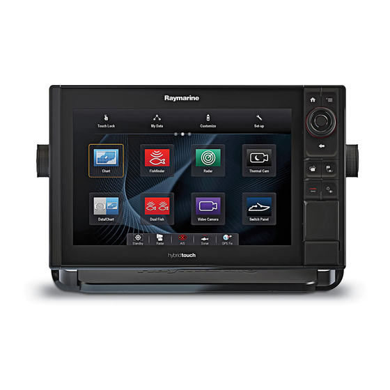
2.5 Product overview - eS Series Your multifunction display includes the features listed below. D13274-1 • MultiTouch capable LCD • Raymarine HybridTouch controls • NMEA 0183 • NMEA 2000 via SeaTalk • Bluetooth • Wi-Fi • Internal GNSS (GPS / GLONASS) receiver •... -
Page 15: Chapter 3 Planning The Installation
Chapter 3: Planning the installation Chapter contents • 3.1 System integration on page 16 • 3.2 Installation checklist on page 22 • 3.3 Multiple data sources (MDS) overview on page 22 • 3.4 Identifying your display variant on page 23 •... -
Page 16: System Integration
Navionics Marine app: • Apple iPhone or iPad • Android-compatible smartphone or tablet For media player control (Touchscreen MFDs only): • Any Bluetooth-enabled device that supports Bluetooth 2.1+ EDR power class 1.5 (supported profile: AVRCP 1.0) eS Series installation instructions... - Page 17 • 1 x bait / fish. GNSS Receiver Any combination of the following: SeaTalk, SeaTalk ng® , or NMEA (external) — 0183 • RS130 GPS Raymarine ® • Raystar125 GPS • Raystar125+GPS (via optional ng® SeaTalk to SeaTalk converter) Instruments — As determined by SeaTalk ng®...
- Page 18 Composite PAL or NTSC video BNC connectors a9x / a12x / e7 / e7D source c Series = 1 e9x / e12x / e165 = 2 eS Series = 1 gS Series = 2 IP camera Multiple • CAM200IP Via SeaTalk...
- Page 19 • Any 600 watt / 1Kw compatible transducer (via optional E66066 adaptor cable) ; OR: • Any Minn Kota transducer (via optional A62363 adaptor cable) Connection via external Raymarine ® Sonar Module: • Any sonar module-compatible transducer DownVision ™ Direct connection to internal...
- Page 20 Thermal camera — • T200 Series SeaTalk (for control), BNC Raymarine ® connector (for video) • T300 Series • T400 Series • T800 Series • T900 Series Remote keypad Multiple • RMK-9 SeaTalk eS Series installation instructions...
- Page 21 Fusion 700 series entertainment SeaTalk systems systems: • MS-IP700 • MS-AV700 PC / laptop Windows-compatible PC or laptop SeaTalk running Raymarine ® Voyage Planner software. Note: Raymarine ® cannot guarantee the compatibility of any third-party devices listed above. Planning the installation...
-
Page 22: Installation Checklist
NOT compliant. It may be necessary to upgrade the software for these non-compliant products to make them compliant. Visit the Raymarine website (www.raymarine.com) to obtain the latest software for your products. If MDS-compliant software is not available and you do... -
Page 23: Identifying Your Display Variant
LightHouse software release V4.32 or later. • All networked gS Series displays must contain LightHouse software release V7.43 or later. • All networked eS Series displays must contain LightHouse software release V14.xx or later. Master / repeater operation From the homescreen: •... -
Page 24: System Protocols
NMEA 0183, most notably in speed and connectivity. Up to 50 units can simultaneously transmit and receive on a single physical bus at any one time, with each node being physically addressable. The standard was specifically intended to allow for eS Series installation instructions... -
Page 25: Data Master
3.7 Data master a whole network of marine electronics from any manufacturer to communicate on a common bus via Any system containing more than one networked standardized message types and formats. multifunction display must have a designated data master. SeaTalk The data master is the display which serves as a SeaTalk is a protocol which enables compatible primary source of data for all displays, it also handles... -
Page 26: Parts Supplied - Es7X Displays
Bezel pieces and Home/Menu button Fixing sets 1.5 m (4.9 ft) Power and data cable (Power/NMEA/Video) SeaTalk ng® to DeviceNet adaptor cable 1 m (3.3 ft.) SeaTalk ng® spur cable 2 m (6.6 ft.) RayNet cable eS Series installation instructions... -
Page 27: Tools Required For Installation
3.10 Tools required for installation 3.11 Selecting a location Warning: Potential ignition source This product is NOT approved for use in hazardous/flammable atmospheres. Do NOT install in a hazardous/flammable atmosphere (such as in an engine room or near fuel tanks). General location requirements When selecting a location for your product it is important to consider a number of factors. - Page 28 250 mm (9.84 in.) issues related to the prevailing conditions. EMC installation guidelines GPS location requirements Raymarine equipment and accessories conform to In addition to general guidelines concerning the the appropriate Electromagnetic Compatibility (EMC) location of marine electronics, there are a number...
- Page 29 Product dimensions • Raymarine equipment and cables connected to it are: – At least 1 m (3 ft) from any equipment transmitting or cables carrying radio signals e.g. VHF radios, cables and antennas. In the case of SSB radios, the distance should be increased to 7 ft (2 m).
- Page 30 Series installation instructions...
-
Page 31: Chapter 4 Cables And Connections
4.21 Fusion network connection on page 50 • 4.22 Fusion NMEA 2000 connection on page 51 • 4.23 Media player connection on page 51 • 4.24 Raymarine mobile app connection on page 52 • 4.25 Bluetooth remote control connection on page 53 Cables and connections... -
Page 32: General Cabling Guidance
Raymarine. Ensure that all data cables are properly shielded • Ensure that any non-Raymarine cables are of the that the cable shielding is intact (e.g. hasn’t been correct quality and gauge. For example, longer scraped off by being squeezed through a tight area). -
Page 33: Connections Overview
4.2 Connections overview Details of the connections available on Raymarine multifunction displays are shown below. eS97 / eS98 / eS127 / eS128 D13281-2 SeaTalk / RayNet Power / NMEA / Video Down- NMEA 600 W Vision 2000 / NMEA Power /... -
Page 34: 3-Pin Power Connection
/ breaker to the positive wire of your products power connection. Power distribution Recommendations and best practice. • The product is supplied with a power cable. Only use the power cable supplied with the product. Do eS Series installation instructions... - Page 35 NOT cover every scenario. If you are unsure how to provide the correct level of protection, please consult an authorized Raymarine dealer or D13348-1 a suitably qualified professional marine electrician. • Alternatively, the supplied power cable may be connected to a suitable breaker or switch on the Implementation —...
-
Page 36: Seatalk Ng® Connections
SeaTalk power requirements The SeaTalk bus requires a 12 V power supply. Power may be provided from: • Raymarine equipment with a regulated 12 V power supply (for example, a SmartPilot SPX course computer); or: eS Series installation instructions... -
Page 37: Nmea 2000 Connection
4.6 NMEA 2000 connection • Other suitable 12 V power supply. Note: SeaTalk does NOT supply power to The display can receive data from NMEA 2000 multifunction displays and other equipment with a devices (e.g. data from compatible engines). The dedicated power supply input. -
Page 38: Seatalk Connection
2 devices to the display's input ports. Posi- tive (+) Ite- Cable Input / / nega- Device color Port output tive (-) Multifunc- White Input Positive tion dis- Green Input Nega- play tive Yellow Output Positive Brown Output Nega- tive eS Series installation instructions... - Page 39 Posi- Note: For Port 1, both the input and output tive (+) communicate at the same baud rate. For example, Ite- Cable Input / / nega- if you have one NMEA 0183 device connected to Device color Port output tive (-) Port 1 INPUT, and another NMEA 0183 device connected to Port 1 OUTPUT, both NMEA devices Orange /...
-
Page 40: Sonar Module And Transducer Connection
CHIRP DownVision sonar Transducer connection — Internal 600 W MFD variant MFDs. direct connection Note: The CPT200 SideVision transducer cannot be connected directly to a DownVsion variant MFD. D12256-2 eS Series installation instructions... -
Page 41: Radar Network Connection
4.10 Radar network connection Transducer connection — Minn Kota transducer Radar units are connected to the SeaTalk network, usually via a Raymarine ® network switch. On smaller systems the Radar may be connected directly to the display’s network connection. Radar connected via network switch D12259-2 1. - Page 42 Note: The power connection is NOT shown in the diagram. If using an Open Array scanner a VCM (Voltage Converter Module) must be connected between the scanner and the power supply. For further information regarding Radar installation (including power connections and mounting), refer to the installation instructions supplied with the Radar. eS Series installation instructions...
- Page 43 A55080D 5 m (16.4 ft) Power and data variety of lengths. digital cable Raymarine network switch to Network cables, available in 10 m (32.8 ft) Power and data A55081D multifunction display. a variety of cable lengths.
-
Page 44: Ga150 Connection
2. Turn the locking collar clockwise until TIGHT. 3. Push to protective boot over the connection on the back of the display. 4. Use the supplied cable tie to secure the protective boot over the connection. eS Series installation instructions... -
Page 45: Ais Connection
NMEA 0183. The compass is connected to the course computer and calibrated via the pilot control head; or: • A Raymarine or third-party fastheading sensor connected to the multifunction display via NMEA 0183. Note: Please contact your dealer or Raymarine technical support for more information. -
Page 46: Keypad Network Connection
For information on connecting an SR50 using D12694-3 SeaTalk please refer to 82257 – SR50 operation 1. MFD which can be downloaded from the Raymarine website: www.raymarine.com. 2. Network connection to MFD or Raymarine ® network switch (RayNet cable) For further information regarding weather receiver installation (including power connection and 3. -
Page 47: Hdmi Video Output
MFDs that do not have a composite video input connection can only be connected to IP cameras. D12916-2 1. MFD 2. External display (See note below) 3. Raymarine 5 m (16.4 ft) HDMI video output cable (A80219) D12178-3 Note: 1. MFD 1. -
Page 48: Ip Camera Connection
3. RayNet to RJ45 SeaTalk adaptor cable 4. Ethernet coupler (R32142) 5. CAM200IP Important: If your IP camera(s) are not detected by your multifunction display, try power cycling the IP camera(s) whilst leaving your multifunction display powered up. eS Series installation instructions... -
Page 49: Thermal Camera Connection
2 connections are required: required if using the optional JCU) • Network connection — required to control the 8. Thermal camera thermal camera via a compatible Raymarine ® 9. Joystick Control Unit (JCU), optional MFD or optional Joystick Control Unit (JCU). -
Page 50: Fusion Network Connection
4.21 Fusion network connection Raymarine recommends the use of a BNC terminated RG59 75ohm (or better) coaxial cable. Fusion 700 and 750 Series marine entertainment systems can be connected directly to the display’s network connection or can be connected to the... -
Page 51: Fusion Nmea 2000 Connection
For more information installation instructions supplied with the unit. refer to the instructions that accompany the media player device. Compatible Fusion units The table below details the Fusion entertainment systems that are compatible with Raymarine ® LightHouse powered MFDs. NMEA 2000 SeaTalk... -
Page 52: Raymarine Mobile App Connection
You can use compatible tablet and smartphone devices as a wireless repeat display or remote control for your multifunction display. Raymarine apps allow you to stream and / or control, remotely what you see on your multifunction display to a compatible device, using a Wi-Fi connection. -
Page 53: Bluetooth Remote Control Connection
4.25 Bluetooth remote control connection You can control the multifunction display wirelessly 1. Select Set-up. using a Raymarine remote control unit. 2. Select System Settings. The remote control uses a Bluetooth wireless 3. Select Wireless Connections. connection. 4. Select Bluetooth > On. -
Page 54: Remote Control Functions
Media player control • Press UP / DOWN (requires a Bluetooth arrow for next / media player paired previous track. to the multifunction • Press SHORTCUT display). button for play / pause. Customizable functions: eS Series installation instructions... - Page 55 Button Application where function available: Open homescreen. SHORTCUT Switch active SHORTCUT application (only available when multiple applications are displayed). Reconnecting the RCU 1. When you pair the RCU-3 with a multifunction display a wireless connection is established. D13326-1 2. When you power off the multifunction display it loses its connection with the RCU-3 after 10 minutes.
- Page 56 Series installation instructions...
-
Page 57: Chapter 5 Mounting
Chapter 5: Mounting Chapter contents • 5.1 Surface mounting on page 58 • 5.2 Bracket (trunnion) mounting on page 59 • 5.3 Rear flush mount kit on page 60 Mounting... -
Page 58: Surface Mounting
9. Slide the unit into place and secure using the be fitted. fixings provided. 10. Attach the Menu/Home buttons keypad, by sliding it down from above the display. eS Series installation instructions... -
Page 59: Bracket (Trunnion) Mounting
5.2 Bracket (trunnion) mounting 2. Slide the backing plate behind the locating tabs as shown below. The display can be mounted on a trunnion bracket. Before mounting the unit ensure that you have: • Selected a suitable location. • Identified the cable connections and route that the cables will take. -
Page 60: Rear Flush Mount Kit
5.3 Rear flush mount kit eS Series displays can be flush mounted from the rear. Instructions on how to flush mount the display from the rear are provided with the kit. Description Part number A80341 eS7 Rear mounting kit eS9 Rear mounting kit... -
Page 61: Chapter 6 Getting Started
Chapter 6: Getting started Chapter contents • 6.1 Switching the unit on and off on page 62 • 6.2 eS Series Controls on page 63 • 6.3 Basic touchscreen operations on page 64 • 6.4 Multi-Touch gestures on page 64 •... -
Page 62: Switching The Unit On And Off
The multifunction displays is now in PowerSave mode. 4. You can wake the unit from PowerSave mode at anytime by pressing a physical button on the multifunction display. Note: PowerSave mode is automatically cancelled if an alarm event occurs. eS Series installation instructions... -
Page 63: Es Series Controls
6.2 eS Series Controls eS Series UniController D13286-1 Description Functions Touch- you can touch the screen to operate screen many common functions, including all menu operations. Home Press to return to the homescreen. Menu Accesses menus. Press again to close menus. -
Page 64: Basic Touchscreen Operations
6.3 Basic touchscreen operations 6.4 Multi-Touch gestures Raymarine a Series and gS Series multifunction Placing and moving the cursor using displays support multi-touch. touch Multi-touch means that the display is capable of To place or move the cursor around the screen on recognizing multiple simultaneous touch inputs. -
Page 65: Touch Icons
6.5 Touch icons 6.6 Homescreen overview — HybridTouch and non-Touch displays Touchscreen multifunction displays can use the BACK and CLOSE icons to move between The Homescreen provides a central point of access the different levels of menus available in each for your display's applications, data and settings. -
Page 66: Databar Status Symbols
Fish mode is active. AIS unit is switched off, or not connected. Autopilot calibration. AIS unit is in Silent Mode. Power steering active. AIS unit is in Silent Mode, with active alarms. Wind Vane mode is active. eS Series installation instructions... -
Page 67: Pages
6.7 Pages Symbol Description AIS unit is connected and switched Pages are made up of 1 to 4 panes that are used on, but has active alarms. to display applications on your multifunction display (MFD). AIS unit is connected and switched Pages are accessed using the icons on the on, but the dangerous and lost alarm Homescreen. - Page 68 7. Select Finish. The Rename Page dialog is displayed. 8. Use the on-screen keyboard to name the page, then select Save. Moving a page on the homescreen With the homescreen displayed: 1. Select the Customize icon. eS Series installation instructions...
-
Page 69: Applications
6.8 Applications FUSION Link application — link to and control a compatible Fusion Chart application — provides a 2D or entertainment system from your 3D graphical view of your charts to help multifunction display. you navigate. Waypoint, route, and track functions enable you to navigate Sirius Audio application —... -
Page 70: Splitscreen Controls
With a page featuring multiple applications displayed: 1. Press the Switch Active button. The active pane pop up is displayed: 2. Press the Switch Active Pane button or use the Rotary control to cycle the active application. eS Series installation instructions... -
Page 71: Screen Overview
6.10 Screen overview D12281- D12196-2 Screen Screen item Description item Description Home Back — On displays with a touchscreen you can • Displays with a touchscreen — Select press the onscreen << (back) icon to go back to the onscreen Home icon to access the a previous menu. - Page 72 The available accented characters are displayed above the text entry field. 3. For characters that have multiple available D13004-1 accents, use the character key to toggle between them. 4. Select the àèò key to enter the character. eS Series installation instructions...
- Page 73 Numeric menu items Using slider bar controls Numeric menu items display numeric data and Slider bar controls provide a graphical representation enables you to either select a predefined value or to of numeric data and enables you to quickly change increase and decrease the value as required.
-
Page 74: Initial Set Up Procedures
As both of these factors wave height. are outside of Raymarine’s control; Raymarine will not be held liable for Minimum safe beam any damage, physical or otherwise, resulting from the use of the automatic... - Page 75 Important: The information below is provided for guidance only and is not exhaustive. Some influencing factors can be unique to certain vessels and / or areas of water and may not be listed below. You should ensure you account for ALL factors that apply to your current situation when making calculations.
-
Page 76: Gnss Status
– Orange = tracking satellite • Azimuth and Elevation — Provides the angle of elevation and azimuth between the location of the receiver and the satellite. Position and fix information The following positional and fix information is provided: eS Series installation instructions... - Page 77 Chart application. In order for your by Japan) receiver and MFD to correlate accurately with your paper charts, they must be using the same datum. Raymarine GPS / GNSS receiver compatibility Global Navigation Satellite Systems (GNSS) Raymarine GPS receivers and GNSS (GPS/GLONASS) receivers are compatible A GNSS is a system of satellites that provides with the following GNSS and SBAS.
- Page 78 • EGNOS Status / Type Name Compatible receivers • MSAS Oper- EGNOS All internal and external Raymarine • GAGAN ational GPS receivers and GNSS receivers • All Others SBAS 2. Select the relevant differential system from Oper- MSAS All internal and external Raymarine...
-
Page 79: Enabling Autopilot Control
6.13 Enabling autopilot control Enabling the autopilot control function — SeaTalk and SPX SeaTalk autopilots To enable control of your SeaTalk or SPX SeaTalk autopilot using your multifunction display follow the steps below. From the Homescreen: 1. Select Set-up. 2. Select System Settings. 3. -
Page 80: Engine Identification
• Run the Engine identification wizard to ensure that your engines are displayed in the correct order in the Data application. eS Series installation instructions... - Page 81 The wizard will now listen for data and assign For engines with a NMEA 2000 CAN bus it may the engine instance as the port engine. be possible to connect to a Raymarine MFD via a SeaTalk system without the use of a Raymarine iii.
-
Page 82: Enabling Ais Functions
• Date Format • Time Format • Local Time (UTC) offset System Preferences • Bearing mode • Variation (manual) • Language Data application • Max RPM range • RPM red zone • RPM red zone value eS Series installation instructions... -
Page 83: Memory Cards And Chart Cards
System Setup Menu. time. Chart cards provide additional or upgraded cartography. Note: Raymarine recommends that you do NOT use the simulator mode whilst navigating. It is recommended that your data is backed up to a memory card on a regular basis. Do NOT save data Note: The simulator will NOT display any real to a memory card containing cartography. -
Page 84: Pairing The Keypad
6.19 Pairing the keypad 6.20 System software updates Raymarine regularly issues software updates for The keypad can control 1 or more multifunction its products that can provide new and enhanced displays. Multiple keypads can be connected to a features and improved performance and usability. - Page 85 2. Compare the latest available software against the 6. Select the products that you want to update. software version of your Raymarine ® products. 3. If the software on the website is newer than the software on your products download the relevant CP 100 v11.12...
-
Page 86: Learning Resources
Internet connection. • Some videos are only available in English. Training courses Raymarine regularly runs a range of in-depth training courses to help you make the most of your products. Visit the Training section of the Raymarine website for more information: •... -
Page 87: Chapter 7 System Checks
Chapter 7: System checks Chapter contents • 7.1 GPS Check on page 88 • 7.2 Radar check on page 88 • 7.3 Sonar check on page 89 • 7.4 Thermal camera setup and checks on page 91 System checks... -
Page 88: Gps Check
Course Over Ground (COG) data is available. Typical HD radar screen Note: Raymarine recommends that you check the displayed vessel position in the chart application against your actual proximity to a known charted object. GPS receivers typically have an accuracy of between 5 and 15 m. -
Page 89: Sonar Check
Description transducers. Target object (such as a buoy) dead ahead. • All variants allow the connection of a Raymarine Target displayed on the radar display is not sonar transducer via a compatible external sonar aligned with the Ship's Heading Marker (SHM). - Page 90 Before attempting to set a waterline or keel offset, find out the vertical separation between the transducer and either the waterline or the bottom of the keel on your vessel, as appropriate. Then set the appropriate depth offset value. eS Series installation instructions...
-
Page 91: Thermal Camera Setup And Checks
7.4 Thermal camera setup and checks UniControl joystick — is used for rotating the camera left or right (panning), or tilting the To ensure correct operation of the thermal camera camera up or down. you should setup and check the camera's main functions. - Page 92 Series installation instructions...
-
Page 93: Chapter 8 Maintaining Your Display
Chapter 8: Maintaining your display Chapter contents • 8.1 Service and maintenance on page 94 • 8.2 Product cleaning on page 94 Maintaining your display... -
Page 94: Service And Maintenance
Best cleaning practices. components. Please refer all maintenance When cleaning products: and repair to authorized Raymarine dealers. Unauthorized repair may affect your warranty. • If your product includes a display screen, do NOT wipe the screen with a dry cloth, as this could Routine equipment checks scratch the screen coating. -
Page 95: Chapter 9 Troubleshooting
Chapter 9: Troubleshooting Chapter contents • 9.1 Troubleshooting on page 96 • 9.2 Power up troubleshooting on page 97 • 9.3 Radar troubleshooting on page 98 • 9.4 GPS troubleshooting on page 99 • 9.5 Sonar troubleshooting on page 100 •... -
Page 96: Troubleshooting
All Raymarine products are, prior to packing and shipping, subjected to comprehensive test and quality assurance programs. However, if you experience problems with the operation of your... -
Page 97: Power Up Troubleshooting
Software corruption In the unlikely event that the products software has become corrupted please try re-flashing the latest software from the Raymarine website. On display products, as a last resort, you can try to perform a ‘Power on Reset’, however this will delete all settings/presets and user data (such as waypoints and tracks) and revert the unit back to factory defaults. -
Page 98: Radar Troubleshooting
Check that the Scanner is correctly connected to a problem Raymarine network switch or SeaTalk crossover coupler (as applicable). Check the status of the Raymarine network switch. Check that SeaTalk / RayNet cables are free from damage. Software mismatch between Contact Raymarine technical support. -
Page 99: Gps Troubleshooting
9.4 GPS troubleshooting Problems with the GPS and their possible causes and solutions are described here. Problem Possible causes Possible solutions “No Fix” GPS status icon is Geographic location or prevailing Check periodically to see if a fix is obtained in better displayed. -
Page 100: Sonar Troubleshooting
/ RayNet network problem. • Check that the unit is correctly connected to the multifunction display or Raymarine network switch. If a crossover coupler or other coupler cable / adapter is used, check all connections ensuring connections are secure, clean and free from corrosion, replace if necessary. - Page 101 Possible causes Possible solutions With the product under load, using a multi-meter, check for high voltage drop across all connectors/fuses etc (this can cause the Fishfinder applications to stop scrolling or the unit to reset/turn off), replace if necessary. Vessel speed too high Slow vessel speed and recheck.
- Page 102 Possible solutions Transducer does not have a speed element Install transducer with speed element to enable speed readings. Incorrect transducer selected (no speed Select a transducer that supports speed measurement from the Transducer displayed) Set-Up menu. eS Series installation instructions...
-
Page 103: Sonar Crosstalk Interference
• Adjust the Interference Rejection Filter. The you may experience some operating in overlapping default setting for all Raymarine MFDs is “Auto”. minor crosstalk interference frequency ranges, you may Changing this setting to “High” might help to... - Page 104 Being able to easily identify the way in which interference is displayed in the Fishfinder application can sometimes be the best and easiest route to dealing with it. eS Series installation instructions...
-
Page 105: Thermal Camera Troubleshooting
VIS / IR switching. image . VIS / IR cable not connected. Ensure that the VIS / IR cable is connected from the camera to the Raymarine system. (The IR-only cable does not support switching). Noisy image. Poor quality or faulty video Ensure that the video cable is no longer than necessary. - Page 106 FFC, a small green square will appear in the upper left corner of the screen. Image is inverted (upside down). Camera “Ball down” setting is Ensure that the Ball down setting within the thermal incorrect. camera system setup menu is set correctly. eS Series installation instructions...
-
Page 107: System Data Troubleshooting
Network problem. Check that all required equipment is connected to the is missing from some but not all network. displays. Check the status of the Raymarine network Switch. Check that SeaTalk / RayNet cables are free from damage. Software mismatch between Contact Raymarine technical support. -
Page 108: Video Troubleshooting
Problems with the video inputs and their possible causes and solutions are described here. Problem Possible causes Possible solutions No signal message on screen Cable or connection fault Check that the connections are sound and free from (video image not displayed) corrosion. eS Series installation instructions... -
Page 109: Wi-Fi Troubleshooting
Ensure that the “Wi-Fi” option is enabled on the iPhone (available from the phone's Settings menu). Ensure that the Raymarine connection is selected as the Wi-Fi network. If a passcode has been specified for the multifunction display's Wi-Fi connection ensure that the same passcode is entered into the iPhone when prompted. -
Page 110: Bluetooth Troubleshooting
Multiple wireless devices running simultaneously (such signal. devices in the vicinity. as laptops, phones, and other wireless devices) can sometimes cause wireless signal conflicts. Temporarily disable each wireless device in turn until you have identified the device causing the interference. eS Series installation instructions... -
Page 111: Touchscreen Troubleshooting
9.12 Touchscreen troubleshooting Problems with the touchscreen and their possible causes and solutions are described here. Problem Possible causes Possible solutions Touchscreen does not operate Touch lock is enabled. Use the Joystick to turn off the touch lock on the home as expected. -
Page 112: Touchscreen Alignment
8. If the operation was unsuccessful at any point during the alignment exercise, an “Incorrect touch detected" message is displayed, the alignment exercise is repeated. 9. After 2 failed alignment exercises you may be asked to perform a precision alignment exercise. eS Series installation instructions... -
Page 113: Miscellaneous Troubleshooting
Check that the power source is of the correct voltage and erratic behavior. sufficient current. Software mismatch on system Go to www.raymarine.com and click on support for the (upgrade required). latest software downloads. Corrupt data / other unknown Perform a factory reset. - Page 114 Series installation instructions...
-
Page 115: Chapter 10 Technical Specification
Chapter 10: Technical specification Chapter contents • 10.1 Product dimensions on page 116 • 10.2 Weight specification - eS Series on page 116 • 10.3 Power specification — eS7x displays on page 117 • 10.4 Power specification — eS9x displays on page 117 •... -
Page 116: Product Dimensions
10.1 Product dimensions 10.2 Weight specification - eS Series eS7x 1,695 Kg (3.74 lbs) eS9x 2,567 Kg (5.66 lbs) eS12x 3,620 Kg (7.98 lbs) D13276 -1 eS7x eS9x eS12x 244.2 mm 299.3 mm 358 mm (9.6 in.) (11.8 in.) (14 in.) 275.2 mm... -
Page 117: Power Specification - Es7X Displays
10.3 Power specification — eS7x 10.4 Power specification — eS9x displays displays Nominal supply voltage 12 V dc to 24 V dc Nominal supply voltage 12 V dc to 24 V dc Operating voltage range 10.8 V dc to 31.2 V dc Operating voltage range 10.8 V dc to 31.2 V dc 15 A in-line fuse... -
Page 118: Power Specification - Es12X Displays
LEN (Refer to Seatalk Resolution 800 x 480 pixels (WVGA) reference manual for further Ratio 16:9 information). Viewing angle • Top / Bottom: 60° / 70° • Left / Right: 70° / 70° Maximum allowable wrongly illuminated pixels eS Series installation instructions... -
Page 119: Display Specification - Es9X Displays
10.7 Display specification — eS9x 10.8 Display specification — eS12x displays displays Size 9 in. Size 12.1 in. Type TFT backlit LED Type TFT backlit LED 24–bit 24–bit Color depth Color depth Resolution 800 x 480 pixels (WVGA) Resolution 1280 x 800 pixels (WXGA) Ratio 16:9 Ratio... -
Page 120: Data Connections And Storage - Es7X Displays
Internal 1.5 (supported profile: AVRCP 1.0) External 2 x MicroSD card slots providing up Storage to 64GB (2 x 32GB cards) Internal External 2 x MicroSD card slots providing up to 64GB (2 x 32GB cards) eS Series installation instructions... -
Page 121: Environmental Specification
• Beidou B1 Signal Acquisition Automatic Almanac Update Automatic Geodetic Datum WGS-84 (alternatives available through Raymarine MFD) Refresh Rate 10 Hz (10 times per second Concurrent GNSS) Antenna • Internal — Ceramic chip mounted near top of unit Position Accuracy •... -
Page 122: Specification
(fore / aft) fan beam. Depth range 0.6 M (2 ft) to 183 m (600 ft). Depending on water conditions, the Sonar channel maybe able to achieve increased depth range over the DownVision ™ channel. eS Series installation instructions... -
Page 123: Electronic Chart Specification
• Navionics Platinum+ • Navionics Fish'N Chip • Navionics Hotmaps Compatible • C-MAP Essentials Jeppesen • C-MAP 4D MAX cartography • C-MAP 4D MAX+ Note: Refer to the Raymarine website (www.rayma- rine.com) for the latest list of supported charts. Technical specification... - Page 124 Series installation instructions...
-
Page 125: Chapter 11 Technical Support
Chapter 11: Technical support Chapter contents • 11.1 Raymarine customer support on page 126 • 11.2 Learning resources on page 126 • 11.3 Third-party support on page 127 Technical support... -
Page 126: Raymarine Customer Support
If you need to request service, please have the following information to hand: Training courses • Product name. Raymarine regularly runs a range of in-depth training courses to help you make the most of your products. • Product identity. Visit the Training section of the Raymarine website •... -
Page 127: Third-Party Support
11.3 Third-party support Contact and support details for third-party suppliers can be found on the appropriate websites. Fusion www.fusionelectronics.com Navionics www.navionics.com Sirius www.sirius.com Technical support... - Page 128 Series installation instructions...
-
Page 129: Chapter 12 Spares And Accessories
Chapter 12: Spares and accessories Chapter contents • 12.1 eS Series spares and accessories on page 130 • 12.2 Digital ClearPulse Transducers and accessories on page 130 • 12.3 DownVision transducers and accessories on page 131 • 12.4 Network hardware on page 132 •... -
Page 130: Es Series Spares And Accessories
12.1 eS Series spares and accessories 12.2 Digital ClearPulse Transducers and accessories Spares The transducers listed below can be connected Part numbers directly to sonar variant MFDs. Item eS7x eS9x eS12x Depth transducers Trunnion R70381 R70384 R70389 Part number Image... -
Page 131: Tm Transducers And
12.3 DownVision transducers and Part number Image Mounting Housing accessories A80215 Thru-hull SS60 (600W, 12° angle) The transducers listed below can be connected directly to DownVision variant MFDs. Depth and temperature transducers Part number Image Mounting Housing A80216 Thru-hull SS60 (600W, 20°... -
Page 132: Network Hardware
RJ45 SeaTalk devices to a HS5 RayNet network switch (in conjunction with suitable adapter cables). • Enables 2 RJ45 SeaTalk cables to be connected together to extend the length of the cabling. Recommended for external installations. eS Series installation instructions... -
Page 133: Network Cable Connector Types
There are 2 types of network cable connector — SeaTalk and RayNet. SeaTalk connector — used for connecting SeaTalk devices to a Raymarine network switch via SeaTalk cables. RayNet connector — used for connecting Raymarine network switches and SeaTalk devices to the multifunction display via RayNet cables. - Page 134 • E55051 (10 m). • A62135 (15 m). • E55052 (20 m). Adapter cable with a RayNet (female) Directly connect a Raymarine radar scanner with an RJ45 socket on one end, and a waterproof SeaTalk (male) cable to a RayNet network switch (e.g.
-
Page 135: Raynet To Raynet Cables And Connectors
12.6 RayNet to RayNet cables and connectors 400 mm (1.3 ft) 2 m (6.56 ft) 5 m (16.4 ft) 10 m (32.8 ft) 20 m (65.6 ft) A80161 A62361 A80005 A62362 A80006 R70014 A80262 100 mm (3.9 in) A80162 D13160-1 Description Typical use Quantity... -
Page 136: Network Cable Types
Spurs from the backbone are lengths) – Thermal camera via PoE injector. used to connect SeaTalk devices. – Additional Raymarine network switch. T-piece connector Used to make junctions in the – PC or laptop using Voyage Planner software. backbone to which devices •... -
Page 137: Seatalk Ng Cables And Accessories
12.9 SeaTalk cables and accessories Description Part No Notes SeaTalk cables and accessories for use with SeaTalk Power A06049 compatible products. cable Description Part No Notes SeaTalk A06031 Terminator SeaTalk starter kit T70134 Includes: SeaTalk T-piece A06028 Provides 1 x spur •... - Page 138 Series installation instructions...
-
Page 139: Appendix A Connectors And Pinouts
Pair 4– Not connected Not connected Not connected D13333-1 Foil Shield Isolated from 0V Power cable cores and colors Signal Color Note: Use only Raymarine RayNet cables when connecting SeaTalk devices. (+) Positive (-) Negative Black Ground Black Connectors and pinouts... - Page 140 STNG Current source to network No current sourced for external devices Current sink from network <160mA (Interface drive only) Signal +12V Screen CanH CanL SeaTalk (not connected) Note: Use only Raymarine cables when connecting to SeaTalk eS Series installation instructions...
-
Page 141: Appendix B Nmea 0183 Sentences
Appendix B NMEA 0183 sentences The display supports the following NMEA 0183 sentences. These are applicable to NMEA 0183 and SeaTalk protocols. Sentence Description Transmit Receive Waypoint arrival alarm sentence ● Autopilot sentence ‘B’ ● ● Bearing and distance to waypoint ●... -
Page 142: Appendix C Nmea Data Bridging
An example of NMEA data bridging is in a system that includes a third-party GPS receiver connected to the NMEA 0183 Input of a Raymarine display. The GPS data messages transmitted by the GPS receiver are repeated to any appropriate devices connected to the display's NMEA 2000 bus. -
Page 143: Appendix D Nmea 2000 Sentences
Appendix D NMEA 2000 sentences The display supports the following NMEA 2000 sentences. These are applicable to NMEA 2000, SeaTalk and SeaTalk 2 protocols. Bridged to Message number Message description Transmit Receive NMEA 0183 ● ● 59392 ISO Acknowledgment ● ●... - Page 144 The following engine alarms are supported. Engine Error Check Engine Over Temperature Low Oil Pressure Low Oil Level Low Fuel Pressure Low System Voltage Low Coolant Level Water Flow Water in Fuel Charge Indicator High Boost Pressure Rev Limit Exceeded eS Series installation instructions...
- Page 145 EGR System Throttle Position Sensor Engine Emergency Stop Mode Warning Level 1 Warning Level 2 Power Reduction Maintenance Needed Engine Comm Error Sub or Secondary Throttle Neutral Start Protect Engine Shutting Down unknown error NMEA 2000 sentences...
- Page 146 Series installation instructions...
- Page 148 www.raymarine.com...
Need help?
Do you have a question about the eS Series and is the answer not in the manual?
Questions and answers