Table of Contents
Advertisement
Quick Links
Advertisement
Table of Contents

Related Manuals for VIA Technologies Video Wall Mini


Summary of Contents for VIA Technologies Video Wall Mini
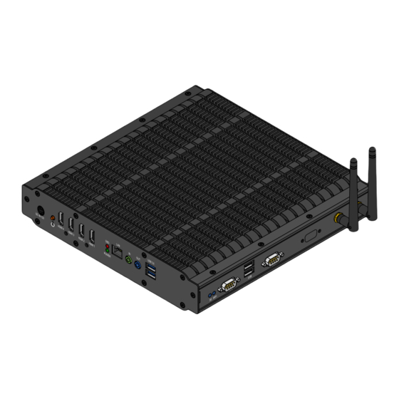
- Page 2 USER MANUAL Video Wall Mini Fanless and Slim size system with 4-display HDMI support 1.03-10312014-140100...
-
Page 3: Regulatory Compliance
The information and product specifications within this document are subject to change at any time, without notice and without obligation to notify any person of such change. VIA Technologies, Inc. reserves the right the make changes to the products described in this manual at any time without prior notice. -
Page 4: Safety Precautions
Battery Recycling and Disposal Only use the appropriate battery specified for this product. Do not re-use, recharge, or reheat an old battery. Do not attempt to force open the battery. Do not discard used batteries with regular trash. Discard used batteries according to local regulations. Safety Precautions Always read the safety instructions carefully. -
Page 5: Box Contents
3Q10A1 A1400 A1400 3Q10A1 3Q10A1 1 x Video Wall Mini system unit 1 x Power cord, 180 cm, Japan Type 1 x Power adaptor, 12V/8.5A 102W 1 x Power cable, 4-hole DC-In jack 2 x HDMI cable strap holder 4 x SATA SSD screws... -
Page 6: Ordering Information
Video Wall Mini User Manual Video Wall Mini User Manual Video Wall Mini User Manual Video Wall Mini User Manual Ordering Information Part Number Part Number Description Description Part Number Part Number Description Description ATG- - - - A1400 A1400... -
Page 7: Table Of Contents
Video Wall Mini User Manual Video Wall Mini User Manual Video Wall Mini User Manual Video Wall Mini User Manual Table of Contents 1. 1. 1. 1. Product Overview ........ Product Overview ................................1 1 1 1 Product Overview Product Overview ........ - Page 8 Video Wall Mini User Manual Video Wall Mini User Manual Video Wall Mini User Manual Video Wall Mini User Manual 4.2. Reset CMOS RAM Jumper................ 25 4.3. SPI Address Select Jumper ..............26 4.4. Recovery BIOS Jumper................27 4.5. VDD/VSUSVDD Mode Select Jumper ........... 28 5.
- Page 9 Video Wall Mini User Manual Video Wall Mini User Manual Video Wall Mini User Manual Video Wall Mini User Manual 6.7. Boot Settings ....................68 6.7.1. Boot Configuration................68 6.7.2. Boot Option Priorities ................69 6.8. Security Settings ..................70 6.8.1.
- Page 10 Video Wall Mini User Manual Video Wall Mini User Manual Video Wall Mini User Manual Video Wall Mini User Manual Lists of Figures Figure 1: Front side layout label..................7 Figure 2: Right side layout label ..................7 Figure 3: Rear side layout label ..................7 Figure 4: Bottom side layout label................
- Page 11 Video Wall Mini User Manual Video Wall Mini User Manual Video Wall Mini User Manual Video Wall Mini User Manual Figure 40: Securing mSATA module................36 Figure 41: Inserting 3G/3.5G SIM card................ 37 Figure 42: Inserting 3G/3.5G module ................. 38 Figure 43: Securing 3G/3.5G module .................
- Page 12 Video Wall Mini User Manual Video Wall Mini User Manual Video Wall Mini User Manual Video Wall Mini User Manual Lists of Tables Table 1: DC-In jack pinout .................... 11 ® Table 2: HDMI port pinout ..................12 Table 3: RJ-45 LAN port pinout................... 14 Table 4: RJ-45 LAN port color definition ..............
-
Page 13: Product Overview
PCIe card slots for mSATA storage and 3G/3.5G connectivity with SIM card slot. The Video Wall Mini’s system chassis is a robust aluminum (top and bottom cover) alloy and it is designed to support VESA-mounting for quick installation and easy maintenance. -
Page 14: Multiple Display Support
1920 x 1080p. 1.1.4. Optimize Integration with Multiple I/O Access Front and right side I/O access enables the Video Wall Mini system to easily access to peripherals, support various applications, easy integration, quick setup and easy maintenance. -
Page 15: Product Specifications
Video Wall Mini User Manual Video Wall Mini User Manual Video Wall Mini User Manual Video Wall Mini User Manual 1.2. Product Specifications Processor Processor Core Logic System Core Logic System Processor Processor Core Logic System Core Logic System VIA QuadCore U4650E 1.0+ GHz processor ... - Page 16 Video Wall Mini User Manual Video Wall Mini User Manual Video Wall Mini User Manual Video Wall Mini User Manual USB 2.0 Controller Controller Controller Controller Integrated USB 2.0 host controller built-in VX11 chipset on system board Interface Interface...
- Page 17 Video Wall Mini User Manual Video Wall Mini User Manual Video Wall Mini User Manual Video Wall Mini User Manual Watchdog Timer Watchdog Timer Watchdog Timer Watchdog Timer Output Output Output Output System reset Interval Interval Interval Interval Programmable 1 ~ 255 sec.
- Page 18 Video Wall Mini User Manual Video Wall Mini User Manual Video Wall Mini User Manual Video Wall Mini User Manual Mechanical Mechanical Mechanical Mechanical Characteristics Characteristics Characteristics Characteristics Construction Construction Construction Construction Aluminum chassis housing with metal I/O plates ...
-
Page 19: Panel Layout
Video Wall Mini User Manual Video Wall Mini User Manual Video Wall Mini User Manual Video Wall Mini User Manual 1.3. Panel Layout Figu Figure re re re 1 1 1 1 : Front side layout label : Front side layout label... - Page 20 Video Wall Mini User Manual Video Wall Mini User Manual Video Wall Mini User Manual Video Wall Mini User Manual Figure Figure 4 4 4 4 : Bottom side layout label : Bottom side layout label Figure Figure : Bottom side layout label...
-
Page 21: Dimensions
Video Wall Mini User Manual Video Wall Mini User Manual Video Wall Mini User Manual Video Wall Mini User Manual 1.4. Dimensions Figure Figure Figure Figure 5 5 5 5 : : : : Front Front Front v v v v iew... - Page 22 Video Wall Mini User Manual Video Wall Mini User Manual Video Wall Mini User Manual Video Wall Mini User Manual Figure Figure 7 7 7 7 : : : : Bottom Bottom v v v v iew d iew dimensions...
-
Page 23: External I/O Pin Descriptions And Functionality
Functionality and Functionality and Functionality and Functionality The Video Wall Mini has a wide selection of interfaces located on the front and right panel as part of the external I/O. 2.1. Front Panel I/O 2.1.1. DC-In Jack (Power Input) The Video Wall Mini comes with a 4-hole DC-In jack that carries 12V DC external power input. -
Page 24: Hdmi ® Port
Video Wall Mini User Manual ® 2.1.3. HDMI Port ® The Video Wall Mini provides four HDMI ports (19-pin HDMI Type A receptacle connector) via discrete S3 5400E graphics processor onboard. The ® HDMI ports allow you to connect up to four digital video devices which ®... -
Page 25: Led Indicators (Power Led And Sata Ssd Led)
Video Wall Mini User Manual 2.1.4. LED Indicators (Power LED and SATA SSD LED) There are two LEDs on the front panel of Video Wall Mini that indicate the status of the system: Power LED flashes in green and indicates system’s power status. -
Page 26: Lan Port (Gigabit Ethernet)
Video Wall Mini User Manual 2.1.5. RJ-45 LAN Port (Gigabit Ethernet) The Video Wall Mini is equipped with a Gigabit Ethernet LAN port. The Gigabit Ethernet LAN port is using 8 Position 8 Contact (8P8C) receptacle connector or commonly referred to as RJ-45. It is fully compliant with IEEE 802.3 (10BASE-T), 802.3u (100BASE-TX), and 802.3ab (1000BASE-T) standards. -
Page 27: Audio Jacks
: Audio jack receptacle stack diagram 2.1.7. USB 3.0 Port The Video Wall Mini is equipped with two USB 3.0 ports. The USB 3.0 port has a maximum data transfer rate up to 5 Gbps and offers a backward compatible with previous USB 2.0 specifications. It gives complete Plug and Play and hot swap capability for external devices. -
Page 28: Right Side Panel
2.2. Right Side Panel 2.2.1. LED Indicators (3G/3.5G and WLAN) There are two LEDs on the right side panel of the Video Wall Mini that indicate the status of the 3G/3.5G and WLAN (WiFi) connectivity: 3G/3.5G flashes in blue and indicates the activity status of 3G/3.5G connectivity. -
Page 29: Usb 2.0 Port
Video Wall Mini User Manual 2.2.3. USB 2.0 Port The Video Wall Mini has two USB 2.0 ports on the right side panel. Each port gives complete Plug & Play and hot swapping capability for external devices. The USB interface complies with USB UHCI, Rev. 2.0. The USB 2.0 pinout is shown below. -
Page 30: Com Connector
Video Wall Mini User Manual 2.2.4. COM Connector The Video Wall Mini system provides one COM connector for serial communications. The COM connector can be configured to operate in RS- 232/RS-422/RS-485 mode by adjusting the BIOS setup items. However, the default setting of COM connector is the standard RS-232. -
Page 31: Onboard Connector And Pin Headers
This chapter provides information about the onboard connectors and pin headers of VIA Video Wall Mini system’s mainboard. 3.1. LPC Connector The Video Wall Mini has one LPC connector for debugging purpose. The connector is labeled as “JLPC1”. The pinout of the connector is shown below. Figure... -
Page 32: Vga Pin Header
Video Wall Mini User Manual 3.2. VGA Pin Header The Video Wall Mini mainboard has an onboard VGA pin header that allows connection of VGA connector cable for analog VGA monitor. The onboard VGA pin header is labeled as “JVGA1”. The pinout of the VGA pin header is shown below. -
Page 33: Spi Pin Header
Video Wall Mini User Manual 3.3. SPI Pin Header The Video Wall Mini mainboard has one SPI (Serial Peripheral Interface) pin header used to connect to the SPI BIOS programming fixture for updating the SPI flash ROM. The SPI pin header is labeled as “SPI1”. The pinout of the SPI pin header is shown below. -
Page 34: System Temperature Sensor Pin Header
Video Wall Mini User Manual 3.4. System Temperature Sensor Pin Header The Video Wall Mini supports an onboard pin header (3-pin) that allows the connection of a temperature sensor cable for detecting the system’s internal temperature. The temperature data can be seen in the BIOS Setup Utility. The pin header is labeled as “J7”. -
Page 35: Onboard Jumpers
Video Wall Mini User Manual Video Wall Mini User Manual Video Wall Mini User Manual Video Wall Mini User Manual 4. 4. 4. 4. Onboard Jumpers Onboard Jumpers Onboard Jumpers Onboard Jumpers Jumper Description Jumper Description Jumper Description Jumper Description A jumper consists of pair conductive pins used to close in or bypass an electronic circuit to set up or configure particular feature using a jumper cap. -
Page 36: System Reset Jumper
Video Wall Mini User Manual Video Wall Mini User Manual Video Wall Mini User Manual Video Wall Mini User Manual 4.1. System Reset Jumper To restart the hardware, temporarily close the jumper of the 2-pin reset pin header. The reset pin header is labeled as “JRST1”. -
Page 37: Reset Cmos Ram Jumper
Video Wall Mini User Manual Video Wall Mini User Manual Video Wall Mini User Manual Video Wall Mini User Manual 4.2. Reset CMOS RAM Jumper The onboard CMOS RAM stores system configuration data and has an onboard battery power supply. To reset the CMOS settings, set the jumper on pins 2 and 3 while the system is off. -
Page 38: Spi Address Select Jumper
Video Wall Mini User Manual Video Wall Mini User Manual Video Wall Mini User Manual Video Wall Mini User Manual 4.3. SPI Address Select Jumper Selection of address for SPI pin header is controlled by the jumper labeled as “J6”. The jumper settings are shown below. -
Page 39: Recovery Bios Jumper
Video Wall Mini User Manual 4.4. Recovery BIOS Jumper The Video Wall Mini mainboard offers a BIOS recovery jumper labeled as “JRC_BIOS1”. To recover the default BIOS program, set the jumper on pins 1 and 2 while the system is off. Return the jumper to pins 2 and 3 afterwards. -
Page 40: Vdd/Vsusvdd Mode Select Jumper
Video Wall Mini User Manual Video Wall Mini User Manual Video Wall Mini User Manual Video Wall Mini User Manual 4.5. VDD/VSUSVDD Mode Select Jumper Selection of VDD/VUSVDD mode jumper is controlled by the jumper labeled as “J9”. The jumper settings are shown below. -
Page 41: Hardware Installation
Video Wall Mini User Manual Video Wall Mini User Manual Video Wall Mini User Manual Video Wall Mini User Manual 5. 5. 5. 5. Hardware Inst Hardware Installation allation Hardware Inst Hardware Inst allation allation This chapter provides the information about hardware installation procedures. -
Page 42: How To Reinstall The Top Cover
Video Wall Mini User Manual Video Wall Mini User Manual Video Wall Mini User Manual Video Wall Mini User Manual 5.2. How to reinstall the top cover Step 1 Step 1 Step 1 Step 1 On the inner side of the top cover, spread the thermal grease evenly on the center area of the heat pipe plate before reinstalling the top cover. - Page 43 Video Wall Mini User Manual Video Wall Mini User Manual Video Wall Mini User Manual Video Wall Mini User Manual Step Step 2 2 2 2 Step Step Align the top cover over the mounting holes on the chassis. Figu...
-
Page 44: How To Install The Ddr3 Sodimm Memory
Video Wall Mini User Manual Video Wall Mini User Manual Video Wall Mini User Manual Video Wall Mini User Manual 5.3. How to install the DDR3 SODIMM memory Step 1 Step 1 Step 1 Step 1 Locate the DDR3 SODIMM memory socket. Align the notch on the memory module with the notch on the SODIMM socket. -
Page 45: How To Remove The Ddr3 Sodimm Memory
Video Wall Mini User Manual Video Wall Mini User Manual Video Wall Mini User Manual Video Wall Mini User Manual 5.4. How to remove the DDR3 SODIMM memory Step 1 Step 1 Step 1 Step 1 To disengage the locking clips, push the locking clips horizontally outward away from the SODIMM memory module. -
Page 46: How To Install The 2.5-Inch Sata Ssd
Video Wall Mini User Manual Video Wall Mini User Manual Video Wall Mini User Manual Video Wall Mini User Manual 5.5. How to install the 2.5-inch SATA SSD Step 1 Step 1 Step 1 Step 1 Remove four screws and pull up hard drive bay. - Page 47 Video Wall Mini User Manual Video Wall Mini User Manual Video Wall Mini User Manual Video Wall Mini User Manual Step Step 3 3 3 3 Step Step Reinstall the hard drive bay with the 2.5-inch SATA SSD, and secure it with screws.
-
Page 48: How To Install The Msata Module
Video Wall Mini User Manual Video Wall Mini User Manual Video Wall Mini User Manual Video Wall Mini User Manual 5.6. How to install the mSATA module Step Step Step Step 1 1 1 1 Align the notch on the mSATA module with the notch on the mini PCIe slot then insert the module at a 30°... -
Page 49: How To Insert Sim Card
Video Wall Mini User Manual Video Wall Mini User Manual Video Wall Mini User Manual Video Wall Mini User Manual 5.7. How to insert SIM card Step Step Step Step 1 1 1 1 Push back firmly the SIM card socket to unlock and open. Pull up the socket and place in the SIM card. -
Page 50: How To Install 3G/3.5G Module And Antenna
Video Wall Mini User Manual Video Wall Mini User Manual Video Wall Mini User Manual Video Wall Mini User Manual 5.8. How to install 3G/3.5G module and antenna Step Step Step Step 1 1 1 1 Align the notch on the 3G/3.5G module (EMIO-1541-00A1) with the notch on the mini PCIe card slot then insert the module at a 30°... - Page 51 Video Wall Mini User Manual Video Wall Mini User Manual Video Wall Mini User Manual Video Wall Mini User Manual Step Step 2 2 2 2 Step Step Once the 3G/3.5G module has been fully inserted, push down the module until the screw holes align with the standoff holes.
- Page 52 Video Wall Mini User Manual Video Wall Mini User Manual Video Wall Mini User Manual Video Wall Mini User Manual Step Step 4 4 4 4 Step Step Insert the 3G/3.5G port connector into the antenna hole from the inside of the chassis.
-
Page 53: How To Install Wlan Usb Module And Antenna
Video Wall Mini User Manual Video Wall Mini User Manual Video Wall Mini User Manual Video Wall Mini User Manual 5.9. How to install WLAN USB module and antenna Step Step 1 1 1 1 Step Step Install the WLAN USB module (EMIO-1533-00A2) and secure it with two screws. - Page 54 Video Wall Mini User Manual Video Wall Mini User Manual Video Wall Mini User Manual Video Wall Mini User Manual Step Step 2 2 2 2 Step Step Insert the WLAN port connector into the antenna hole from the inside of the chassis.
- Page 55 Video Wall Mini User Manual Video Wall Mini User Manual Video Wall Mini User Manual Video Wall Mini User Manual Step Step 3 3 3 3 Step Step Attach the WLAN board to board cable to the WLAN USB module. Then attach the other end of the cable to the “JUSB2_3”...
-
Page 57: Bios Setup Utility Bios Setup Utility
Video Wall Mini User Manual Video Wall Mini User Manual Video Wall Mini User Manual Video Wall Mini User Manual 6. 6. 6. 6. BIOS Setup Utility BIOS Setup Utility BIOS Setup Utility BIOS Setup Utility 6.1. Entering the BIOS Setup Utility... -
Page 58: System Overview
Video Wall Mini User Manual Video Wall Mini User Manual Video Wall Mini User Manual Video Wall Mini User Manual 6.4. System Overview The System Overview screen is the default screen that is shown when the BIOS Setup Utility is launched. This screen can be accessed by traversing the navigation bar to the “Main”... -
Page 59: System Date
Video Wall Mini User Manual Video Wall Mini User Manual Video Wall Mini User Manual Video Wall Mini User Manual 6.4.4. System Date This section shows the current system date. Press Tab Tab to traverse right and Shift+Tab Shift+Tab to traverse left through the month, day, and year segments. The + + + +... -
Page 60: Advanced Settings
Video Wall Mini User Manual Video Wall Mini User Manual Video Wall Mini User Manual Video Wall Mini User Manual 6.5. Advanced Settings The Advanced Settings screen shows a list of categories that can provide access to a sub-screen. Sub-screen links can be identified by the preceding right-facing arrowhead. -
Page 61: Acpi Settings
Video Wall Mini User Manual Video Wall Mini User Manual Video Wall Mini User Manual Video Wall Mini User Manual 6.5.1. ACPI Settings ACPI grants the operating system direct control over system power management. The ACPI Configuration screen can be used to set a number of power management related functions. -
Page 62: S5 Rtc Wake Settings
Video Wall Mini User Manual Video Wall Mini User Manual Video Wall Mini User Manual Video Wall Mini User Manual 6.5.2. S5 RTC Wake Settings Figure Figure 51 51: Illustration of the : Illustration of the S5 RTC S5 RTC Wake Settings screen... -
Page 63: Cpu Configuration
Video Wall Mini User Manual Video Wall Mini User Manual Video Wall Mini User Manual Video Wall Mini User Manual 6.5.3. CPU Configuration The CPU Configuration screen shows detailed information about the built-in processor. Figure Figure Figure Figure 52 52 52... -
Page 64: Sata Configuration
Video Wall Mini User Manual Video Wall Mini User Manual Video Wall Mini User Manual Video Wall Mini User Manual 6.5.4. SATA Configuration The SATA Configuration screen allows the user to view and configure the SATA configuration settings. Figure Figure... -
Page 65: Usb Configuration
Video Wall Mini User Manual Video Wall Mini User Manual Video Wall Mini User Manual Video Wall Mini User Manual 6.5.5. USB Configuration The USB Configuration screen shows the number of connected USB devices. Additionally, support for various USB features can be enabled or disabled. - Page 66 Video Wall Mini User Manual Video Wall Mini User Manual Video Wall Mini User Manual Video Wall Mini User Manual 6.5.5.3. 6.5.5.3. 6.5.5.3. 6.5.5.3. XHCI Hand XHCI Hand XHCI Hand XHCI Hand- - - - off This is a workaround for Operating Systems without XHCI hand-off support.
-
Page 67: F71869 Super Io Configuration
Video Wall Mini User Manual Video Wall Mini User Manual Video Wall Mini User Manual Video Wall Mini User Manual 6.5.6. F71869 Super IO Configuration The F71869 Super IO Configuration screen allows the user to set system Super IO Chip parameters. -
Page 68: Pc Health Status
Video Wall Mini User Manual Video Wall Mini User Manual Video Wall Mini User Manual Video Wall Mini User Manual 6.5.7. PC Health Status The PC Health Status screen displays and monitored aspects of system such as CPU temperature, system temperature, and voltages of the power planes. -
Page 69: Clock Generator Configuration
Video Wall Mini User Manual Video Wall Mini User Manual Video Wall Mini User Manual Video Wall Mini User Manual 6.5.8. Clock Generator Configuration The Clock Generator Configuration screen enables access to the Spread Spectrum Setting feature. Figure Figure 57... -
Page 70: Chipset Settings
Video Wall Mini User Manual Video Wall Mini User Manual Video Wall Mini User Manual Video Wall Mini User Manual 6.6. Chipset Settings The Chipset Settings screen shows a list of categories that can provide access to a sub-screen. Sub-screen links can be identified by the preceding right- facing arrowhead. -
Page 71: Dram Configuration
Video Wall Mini User Manual Video Wall Mini User Manual Video Wall Mini User Manual Video Wall Mini User Manual 6.6.1. DRAM Configuration The DRAM Configuration screen has two features for controlling the system DRAM. All other DRAM features are automated and cannot be accessed. - Page 72 Video Wall Mini User Manual Video Wall Mini User Manual Video Wall Mini User Manual Video Wall Mini User Manual 5 5 5 5 66 66 MHz 66 66 The 566 MHz option forces the BIOS to be fixed at 1132 MHz for DDR3 memory modules.
-
Page 73: Video Configuration
Video Wall Mini User Manual Video Wall Mini User Manual Video Wall Mini User Manual Video Wall Mini User Manual 6.6.2. Video Configuration The Video Configuration screen has features for controlling the integrated graphics controller in the VX11 chipset. Figure... - Page 74 Video Wall Mini User Manual Video Wall Mini User Manual Video Wall Mini User Manual Video Wall Mini User Manual 6.6.2.4. 6.6.2.4. Select Display Device 1 and 2 Select Display Device 1 and 2 6.6.2.4. 6.6.2.4. Select Display Device 1 and 2...
-
Page 75: Pmu_Acpi Configuration
Video Wall Mini User Manual Video Wall Mini User Manual Video Wall Mini User Manual Video Wall Mini User Manual 6.6.3. PMU_ACPI Configuration The PMU_ACPI Configuration screen can be used to set a number of power management related functions. Figure... - Page 76 Video Wall Mini User Manual Video Wall Mini User Manual Video Wall Mini User Manual Video Wall Mini User Manual 6.6.3.1. 6.6.3.1. Other Control Other Control 6.6.3.1. 6.6.3.1. Other Control Other Control Figure Figure 62 62: Illustration of Other Co...
-
Page 77: Hdac Configuration
Video Wall Mini User Manual Video Wall Mini User Manual Video Wall Mini User Manual Video Wall Mini User Manual 6.6.4. HDAC Configuration HDAC Configuration Parameters. Figure Figure 63 63: Illustration of HDAC Configuration screen : Illustration of HDAC Configuration screen... -
Page 78: Others Configuration
Video Wall Mini User Manual Video Wall Mini User Manual Video Wall Mini User Manual Video Wall Mini User Manual 6.6.5. Others Configuration The Others Configuration screen can be used to set Watchdog Timer Configuration. Figure Figure Figure Figure 64... - Page 79 Video Wall Mini User Manual Video Wall Mini User Manual Video Wall Mini User Manual Video Wall Mini User Manual 6.6.5.4. 6.6.5.4. 6.6.5.4. 6.6.5.4. WATCHDOG Timer COUNT WATCHDOG Timer COUNT WATCHDOG Timer COUNT WATCHDOG Timer COUNT The WATCHDOG Timer COUNT feature determines the length of time the timer should count when the timer is first triggered.
-
Page 80: Boot Settings
Video Wall Mini User Manual Video Wall Mini User Manual Video Wall Mini User Manual Video Wall Mini User Manual 6.7. Boot Settings The Boot Settings screen has a single link that goes to the Boot Configuration Boot Configuration Boot Configuration... -
Page 81: Boot Option Priorities
Video Wall Mini User Manual Video Wall Mini User Manual Video Wall Mini User Manual Video Wall Mini User Manual 6.7.2. Boot Option Priorities The Boot Option Priorities screen lists all bootable devices. 6.7.2.1. 6.7.2.1. 6.7.2.1. 6.7.2.1. Launch PXE OpROM policy... -
Page 82: Security Settings
Video Wall Mini User Manual Video Wall Mini User Manual Video Wall Mini User Manual Video Wall Mini User Manual 6.8. Security Settings The Security Settings screen provides a way to restrict access to the BIOS or even the entire system. -
Page 83: Save & Exit
Video Wall Mini User Manual Video Wall Mini User Manual Video Wall Mini User Manual Video Wall Mini User Manual 6.9. Save & Exit The Save & Exit Configuration screen has the following features: Figure Figure Figure Figure 67 67 67 67: Illustration of Save &... -
Page 84: Discard Changes And Reset
Video Wall Mini User Manual Video Wall Mini User Manual Video Wall Mini User Manual Video Wall Mini User Manual 6.9.4. Discard Changes and Reset This command reverts all changes to the settings that were in place when the BIOS Setup Utility was launched. The “F7” hotkey can also be used to trigger this command. -
Page 85: Software And Technical Supports
Technical ftware and Technical Supports Supports Supports Supports 7.1. Microsoft Support The VIA Video Wall Mini system is highly compatible with Microsoft Windows operating systems. 7.1.1. Driver Installation Microsoft Driver Support Microsoft Driver Support Microsoft Driver Support Microsoft Driver Support... -
Page 87: Appendix A. Quick Setup Diagram Appendix A. Quick Setup Diagram
Quick Setup Diagram Quick Setup Diagram Quick Setup Diagram A setup diagram of Video Wall system using the Video Wall Mini is shown in figure below. The quick setup diagram is only intended to be used as a reference guide for setting up Video Wall system. - Page 88 Connecting the video wall display Connecting the video wall display The front side panel of Video Wall Mini has four HDMI ports (HDMI 1 ~ HDMI 4). Connect the HDMI cables of video wall displays to its designated HDMI port numbers on Video Wall Mini (e.g. video wall display number 1 and 2 must be connected to HDMI 1 and HDMI 2 ports respectively).
- Page 89 The Video Wall Mini has a reserved HDMI cutout on the rear side panel for additional HDMI In port on the system. The HDMI In port can be installed via onboard HDMI module controller. The additional HDMI In port can support external digital/video sources such as Notebook PC, DVD player and etc.
Need help?
Do you have a question about the Video Wall Mini and is the answer not in the manual?
Questions and answers