
Subscribe to Our Youtube Channel
Related Manuals for VIA Technologies Mobile360 L900


Summary of Contents for VIA Technologies Mobile360 L900
- Page 1 USER MANUAL VIA Mobile360 L900 Fanless ultra-compact in-vehicle system 1.00-04122020...
- Page 2 VIA Technologies, Inc. reserves the right the make changes to the products described in this manual at any time without prior notice.
- Page 3 Battery Recycling and Disposal • Only use the appropriate battery specified for this product. • Do not re-use, recharge, or reheat an old battery. • Do not attempt to force open the battery. • Do not discard used batteries with regular trash. •...
- Page 4 VIA Mobile360 L900 User Manual Box Contents • 1 x VIA Mobile360 L900 system • 2 x Phoenix plug to DC jacks (DC-in & DC-out) • 1 x COM cable (for debugging) • 1 x GPS antenna • 2 x Wi-Fi/BT antennas...
-
Page 5: Table Of Contents
Installing the FOV Cameras and FAKRA Cables ................... 18 Unplugging the FAKRA Cable ......................19 Connecting VIA Mobile360 L900 to the Vehicle's Ignition (IGN) ............20 Installing the Phoenix Plug to DC Jack ....................21 Software and Technical Support ........................22 Linux Support............................ - Page 6 VIA Mobile360 L900 User Manual Appendix A Installing Wireless Accessories ..................... 23 Installing the Mobile Broadband MiniPCIe Module ................23 Appendix B Installing Mounting Bracket ......................26 Appendix C Wi-Fi Support Channel Maps ......................29 Jetson TX1 ............................29 Jetson TX2 ............................30 Appendix D CAN/COM Conversion Cable ......................
- Page 7 Figure 01: Front panel I/O layout ......................... 4 Figure 02: Back panel I/O layout .......................... 4 Figure 03: Dimensions of the VIA Mobile360 L900 (front view) ................5 Figure 04: Dimensions of the VIA Mobile360 L900 (side view) ................5 Figure 05: Dimensions of the VIA Mobile360 L900 (bottom view) ..............
- Page 8 VIA Mobile360 L900 User Manual List of Tables Table 01: HDMI port pinouts ..........................6 Table 02: USB 3.0 ports pinouts .......................... 6 Table 03: Micro USB 2.0 port pinouts ......................... 7 Table 04: Gigabit Ethernet port pinouts ......................7 Table 05: Gigabit Ethernet port LED color definition ..................
-
Page 9: Product Overview
1.1.3 Optimized Integration with Multiple I/O Access With front and back panel I/O access, the VIA Mobile360 L900 can be easily configured to support a wide variety of applications with easy integration and quick setup. -
Page 10: Support For A Wide Range Of Power Sources
VIA Mobile360 L900 User Manual 1.1.5 Support for a Wide Range of Power Sources The VIA Mobile360 L900 supports a wide range of power inputs from 9V to 36V DC. The system's flexible power input enables deployment in a broad variety of in-vehicle environments. - Page 11 VIA Mobile360 L900 User Manual Audio • Realtek ALC5658 Audio Codec HDMI • Integrated HDMI 2.0 transmitter supports 4K display Expansion I/O • 1 miniPCIe slot (USB only) Front Panel I/O • 2 USB 3.0 ports • 1 Micro USB 2.0 port (for debugging) •...
-
Page 12: Layout Diagram
VIA Mobile360 L900 User Manual Dimensions • 240mm (W) x 53mm (H) x 180mm (D) (9.45" x 2.09" x 7.09") Weight • 3.0kg (6.61lbs) Compliance • Notes: 1. As the operating temperature provided in the specifications is a result of testing performed in a testing chamber, a number of variables can influence this result. -
Page 13: Product Dimensions
VIA Mobile360 L900 User Manual Figure 02: Back panel I/O layout 1.4 Product Dimensions Figure 03: Dimensions of the VIA Mobile360 L900 (front view) Figure 04: Dimensions of the VIA Mobile360 L900 (side view) - Page 14 VIA Mobile360 L900 User Manual Figure 05: Dimensions of the VIA Mobile360 L900 (bottom view)
-
Page 15: External I/O Pin Descriptions And Functionality
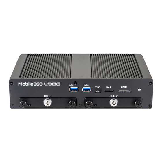
2.2 USB 3.0 Port The VIA Mobile360 L900 is equipped with two USB 3.0 ports on the front panel. Each USB 3.0 port has a maximum data transfer rate of up to 5Gbps and is backwards compatible with the USB 2.0 specification. The USB ports provides complete Plug and Play and hot swap capabilities for external devices. -
Page 16: Micro Usb 2.0 Port
2.3 Micro USB 2.0 Port The VIA Mobile360 L900 is equipped with one Micro USB 2.0 port located on the front panel. The Micro USB 2.0 port supports OTG (On-The-Go) for debugging. The pinouts of the Micro USB 2.0 port are shown below. -
Page 17: Micro Sd Card Slot
2.5 Micro SD Card Slot The VIA Mobile360 L900 comes with a Micro SD card slot located on the front panel with support for a maximum storage capacity of 32GB. The pinouts of the Micro SD card slot are shown below. -
Page 18: Dio Port
2.7 DIO Port The VIA Mobile360 L900 is equipped with a DIO port located on the back panel. The DIO port offers a Digital I/O communication interface to support 8-bit GPIO. The pinouts of the DIO port are shown below. -
Page 19: Can Bus Port
2.10 CAN Bus Port The VIA Mobile360 L900 is equipped with a CAN bus port located on the back panel. The CAN bus port supports one CAN bus and one debug COM (TX/RX) using a CAN/COM conversion cable. The CAN bus supports protocol specification Version 2.0 B. -
Page 20: Dc-In Jack
Table 13: Power button behavior description 2.13 DC-In Jack The VIA Mobile360 L900 integrates a 4-pole Phoenix DC-in jack that carries a 9V~36V DC external power input. The pinouts of the 4-pole Phoenix DC-in jack are shown below. Signal... - Page 21 VIA Mobile360 L900 User Manual Figure 21: 4G and GPS antenna connectors diagram...
-
Page 22: Onboard I/O
This chapter provides information about the onboard I/O connector on the VIA Mobile360 L900. 3.1 MiniPCIe Slot The VIA Mobile360 L900 is equipped with a miniPCIe slot for wireless networking options such as a 4G module. The pinouts of the miniPCIe slot are shown below. -
Page 23: Hardware Installation
VIA Mobile360 L900 User Manual 4. Hardware Installation This chapter provides information about the hardware installation procedures. 4.1 Installing the 2.5" SATA HDD/SSD Step 1 Insert the key and turn it in a counter clockwise direction to unlock the SATA HDD/SSD bay. Then unscrew the two thumbscrews. - Page 24 VIA Mobile360 L900 User Manual Step 3 Slide the 2.5" SATA HDD/SSD into the SATA HDD/SSD bay. Then secure it with four screws. Figure 25: Installing the 2.5" SATA HDD/SSD Step 4 Reinstall the SATA HDD/SSD bays. Figure 26: Reinstalling the SATA HDD/SSD bays...
-
Page 25: Installing The Wi-Fi/Bt Antennas
VIA Mobile360 L900 User Manual 4.2 Installing the Wi-Fi/BT Antennas Step 1 Locate the two Wi-Fi/BT antenna connectors on the back panel of the VIA Mobile360 L900. Step 2 Install the two provided Wi-Fi/BT antennas. Figure 27: Installing the Wi-Fi/BT antennas 4.3 Installing the GPS Antenna... -
Page 26: Installing The Fov Cameras And Fakra Cables
Figure 29: Connecting the FOV camera to the FAKRA cable Step 2 Connect the FAKRA cable to the FAKRA connector for camera-in on the VIA Mobile360 L900. Figure 30: Connecting the FAKRA cable to the FAKRA connector... -
Page 27: Unplugging The Fakra Cable
VIA Mobile360 L900 User Manual 4.5 Unplugging the FAKRA Cable Step 1 Firmly press and hold the locking clip on the FAKRA cable's connector. Step 2 Then pull the FAKRA cable's connector to unplug it. Figure 31: Uplugging the FAKRA cable... -
Page 28: Connecting Via Mobile360 L900 To The Vehicle's Ignition (Ign)
Connect a wire to pin no. 8 on the DIO port. Then connect the other end of the wire into the Ignition (IGN) signal of the vehicle. For details of where to find the IGN on your vehicle, please refer to the car manufacturer. Figure 33: VIA Mobile360 L900 and IGN connection method diagram... -
Page 29: Installing The Phoenix Plug To Dc Jack
Figure 34: Connecting the battery cables onto the Phoenix plug to DC jack Step 2 Connect the Phoenix plug to DC jack into the DC-in jack on the VIA Mobile360 L900, and then secure it with its two screws. Figure 35: Connecting the Phoenix plug to DC jack... -
Page 30: Software And Technical Support
VIA Mobile360 L900 User Manual 5. Software and Technical Support 5.1 Linux Support The VIA Mobile360 L900 features a complete software evaluation image featuring the Linux kernel 4.9 operating system. 5.2 Technical Support and Assistance • For technical support and additional assistance, contact your local sales representative or board distributor, or go to https://www.viatech.com/en/support/driver-support-fag/technical-support/... -
Page 31: Appendix A Installing Wireless Accessories
VIA Mobile360 L900 User Manual Appendix A Installing Wireless Accessories This chapter provides information on how to install the mobile broadband miniPCIe module in the VIA Mobile360 L900. A.1 Installing the Mobile Broadband MiniPCIe Module Step 1 First, remove the two SATA HDD/SSD bays. Refer to steps 1 & 2 of section 4.1 for complete instructions. - Page 32 VIA Mobile360 L900 User Manual Step 3 Remove the bottom plate cover. Figure 37: Removing the bottom plate cover Step 4 Align the notch on the mobile broadband module (4G module) with its counterpart on the miniPCIe slot, then insert the module at a 30° angle. Push down the module until the screw holes align with the mounting hole on the standoff and then secure the module with two screws.
- Page 33 VIA Mobile360 L900 User Manual Step 5 Gently connect the 4G antenna cable to the micro-RF connector labeled "MAIN" on the mobile broadband module. Then, reinstall the bottom plate cover. Figure 39: Connecting the 4G antenna cable to the micro-RF connector on the module Step 6 Install the 4G antenna into the 4G antenna connector.
-
Page 34: Appendix B Installing Mounting Bracket
Figure 41: Mounting bracket parts Step 1 Flip over the VIA Mobile360 L900. Install it onto the top casing of the bracket as shown in the figure below. Figure 42: Installing the VIA Mobile360 L900 onto the top casing... - Page 35 VIA Mobile360 L900 User Manual Step 2 Flip over the base cover. Align the four screws on the base cover with the screw holes on the top casing, and then gently install the base cover. Figure 43: Installing the base cover Step 3 Secure the top casing and base cover together with the four M6 nuts as shown in the figure below.
- Page 36 VIA Mobile360 L900 User Manual Step 4 Find a suitable surface to mount the VIA Mobile360 L900. Drill four holes and make sure the distance between the holes are perfectly matched with the mounting bracket's holes. Step 5 Install the VIA Mobile360 L900 and secure it with M8 four screws.
-
Page 37: Appendix C Wi-Fi Support Channel Maps
VIA Mobile360 L900 User Manual Appendix C Wi-Fi Support Channel Maps The VIA Mobile360 L900 comes with two World Wide safe Wi-Fi support channel maps for the Jetson TX1 and Jetson TX2. The two tables below shows the World Wide safe channel maps. -
Page 38: Jetson Tx2
VIA Mobile360 L900 User Manual C.2 Jetson TX2 Channel Number Frequency (MHz) 11b/g/n20 2412 2417 2422 2427 2432 2437 2442 2447 2452 2457 2462 2467 2472 Channel Number Frequency (MHz) 11a/n20/ac20 5180 5200 5220 5240 5260 DFS - P 5280... -
Page 39: Appendix Dcan/Com Conversion Cable
Appendix D CAN/COM Conversion Cable The VIA Mobile360 L900 comes with a CAN/COM conversion cable. The CAN/COM conversion cable supports one CAN bus port and one COM debug port (TX/RX). The pinouts of CAN bus and COM debug ports are shown below. - Page 40 Taiwan Headquarters Japan China 1F, 531 Zhong-zheng Road, 940 Mission Court 3-15-7 Ebisu MT Bldg. 6F, Tsinghua Science Park Bldg. 7 Xindian Dist., New Taipei City 231 Fremont, CA 94539, Higashi, Shibuya-ku No. 1 Zongguancun East Road, Taiwan Tokyo 150-0011 Haidian Dist., Beijing, 100084 Japan China...
Need help?
Do you have a question about the Mobile360 L900 and is the answer not in the manual?
Questions and answers