Table of Contents
Advertisement
Quick Links
ACS-2645 Box PC
User Manual
Release Date
Revision
Aug, 2014
V1.2
® 2014 Aplex Technology, Inc.
All Rights Reserved.
Published in Taiwan
Aplex Technology, Inc.
15F-1, No.186, Jian Yi Road, Zhonghe District, New Taipei City 235, Taiwan
Tel: 886-2-82262881 Fax: 886-2-82262883 E-mail:
aplex@aplex.com.tw
URL:
www.aplex.com.tw
ACS-2645 User Manual
1
Advertisement
Table of Contents

Related Manuals for Aplex ACS-2645


Summary of Contents for Aplex ACS-2645
-
Page 1: User Manual
ACS-2645 Box PC User Manual Release Date Revision Aug, 2014 V1.2 ® 2014 Aplex Technology, Inc. All Rights Reserved. Published in Taiwan Aplex Technology, Inc. 15F-1, No.186, Jian Yi Road, Zhonghe District, New Taipei City 235, Taiwan Tel: 886-2-82262881 Fax: 886-2-82262883 E-mail: aplex@aplex.com.tw... -
Page 2: Warning
Electric Shock Hazard – Do not operate the machine with its back cover removed. There are dangerous high voltages inside. ACS-2645 User Manual... -
Page 3: Packing List
Always disconnect power when the system is not in use. ◆ Disconnect power when you change any hardware devices. For instance, when you connect a jumper or install any cards, a surge of power may damage the electronic components or the whole system. ACS-2645 User Manual... -
Page 4: Table Of Contents
3.5 Chipset Settings................... 42 3.6 Boot Settings..................46 3.7 Security Settings...................48 3.8 Save & Exit Settings................49 3.9 Examples of GPIO Programming…………………………………………51 Chapter 4 Installation of Drivers 4.1 Intel Chipset Driver.…………………………...………….…...……………59 4.2 Intel VGA Chipset Driver..…..…..……..…………………………..62 4.3 Intel Network Adapter Driver……............65 ACS-2645 User Manual... - Page 5 4.4 Realtek Audio Driver Installation………………………………….….……68 Figures Figure 1.1: Dimensions of ACS-2645 ……………..…………………………...7 Figure 1.2: Front View of ACS-2645…………….…………………………..9 Figure 1.3: Rear View of ACS-2645………………….………………………..9 Figure 2.1: Mainboard Dimensions……………………………………………16 Figure 2.2: Jumpers and Connectors Location-TOP…………………...……17 Figure 2.3: Jumpers and Connectors Location- Bottom………………….…18...
-
Page 6: Specifications
Default: Wall mount / Option: Din Rail mount (single or dual) Dimensions(WxHxD) 211.2(W) x 203.5(H) x 131.2(D) 211.2(W) x 203.5(H) x 157.3(D) (with DVD Device) Gross Weight 5kgs 0~50 °C Operating Temperature Storage Temperature -20~60 °C Storage Humidity 10%~90%@ 40°C, non-condensing Certificate CE / FCC Class A ACS-2645 User Manual... -
Page 7: Dimensions
1.2 Dimensions ACS-2645 User Manual... -
Page 8: Figure 1.1: Dimensions Of Acs-2645
Figure 1.1: Dimensions of ACS-2645 ACS-2645 User Manual... -
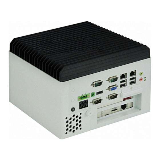
Page 9: Brief Description
Machine Vision, Process Control, Data Terminal, TI, Surveillance, etc. and running factory operations from small visual interface and maintenance applications to large control process applications. ACS-2645 works very well along with any of our Display series and it absolutely can provide an easy way to perform control and field maintenance. -
Page 10: Installation Of Hdd
Pull out the chassis towards the I/O side after unscrewing as shown in the picture. Step 2 There is 1 screw to deal with when enclosing or removing the HDD bracket . Loosen screws and draw the HDD bracket out. Loosen 4 screws ACS-2645 User Manual... - Page 11 Then you can replace HDD. Step 3 Tighten the 1 screw as shown in the picture. That’s how it should look after it has been installed. ACS-2645 User Manual...
-
Page 12: Installation Of Pci Add-On
** Half Expansion-card limit to be not more than 175mm length Step 3 Tighten the 1 screw as shown in the picture. That’s how it should look after it has been installed. ACS-2645 User Manual... -
Page 13: Mainboard Specifications
Up to 1920 x1200 for HDMI Up to 1440 x 900 for LVDS1 (D2550) Up to 1366 x 768 for LVDS1 (N2600/N2800) Up to 1920 x 1200 for LVDS2 (D2550) Up to 1600 x 1200 for LVDS2 (N2600/N2800) Dual Display CRT+LVDS1 CRT+LVDS2 ACS-2645 User Manual... - Page 14 1 x mini-PCI-express slot (PCIe1 option:MPCIE or PCIE1X) 1 x CRT 2x6 Pin Header Power 1 x 3-pin power input connector (Wide range DC+9V~32V) Management DC12V output by 2x2 pin Connectors Power on/off switch by TB-522 or TB-523 Switches and ACS-2645 User Manual...
- Page 15 12V /1.25A (Intel Atom D2550 processor with 2GB DDR3 DRAM) Power 12V /1.18A (Intel Atom N2800 processor with 2GB DDR3 DRAM) Consumption 12V /0.95A (Intel Atom N2600 processor with 2GB DDR3 DRAM) EMI/EMS Meet CE/FCC class A ACS-2645 User Manual...
-
Page 16: Board Dimensions
2.2 Board Dimensions Figure 2.1: Mainboard Dimensions ACS-2645 User Manual... -
Page 17: Jumpers And Connectors Location
2.3 Jumpers and Connectors Location Board Top Figure 2.2 Jumpers and Connectors Location-TOP ACS-2645 User Manual... -
Page 18: Figure 2.3: Jumpers And Connectors Location- Bottom
Board Bottom Figure 2.3: Jumpers and Connectors Location- Bottom ACS-2645 User Manual... -
Page 19: Jumpers Setting And Connectors
DC IN Power (Default) Close 2-3 ATX 12V_IN (ATX Power) 4. PS_ON: (2.0mm Pitch 1X3 Pin Header),ATX Power and Auto Power on jumper setting. Mode (DC_IN) Close 1-2 Auto Power on (Default) Close 2-3 or Open 1-2 ATX Power ACS-2645 User Manual... - Page 20 Pin2 Ground Pin3 DC+12V Pin4 DC+12V 7. ATX1 (option): (2.0mm Pitch 1X3 Pin wafer connector),connect PSON and 5VSB and Ground signal,support ATX Power model. Reserved. Pin# Signal Name Pin1 ATX PSON PIN2 ATX Ground PIN3 ATX 5VSB ACS-2645 User Manual...
- Page 21 Up to 4GB ASB-M7101-N2800 SODIMM1/SODIMM2 Up to 4GB ASB-M7101-N2600 SODIMM1 Up to 2GB 11. VGA: (CRT DB15 Connector),Video Graphic Array Port, provide high-quality video output. they can not work at the same time for VGA and VGA_PH. ACS-2645 User Manual...
- Page 22 (2.0mm Pitch 1x6 Pin wafer connector), Backlight control connector for LVDS1. Pin# Signal Name +DC12V +DC12V Ground Ground BKLT_EN BKLT_CTRL Note: Pin6 is backlight control signal, support DC or PWM mode, mode select at BIOS CMOS menu. ACS-2645 User Manual...
- Page 23 (2.54mm Pitch 2x4Pin Socket), AT24C02 socket, The EEPROM is set for the resolution of LVDS2. The resolution default is:1280*1024. According to the needs of customers set. 16. INVT2: (2.0mm Pitch 1x6 Pin wafer connector), Backlight control connector for LVDS2. ACS-2645 User Manual...
- Page 24 LVDS2_VDD5 Ground Ground LVDS2_VDD33 LVDS2_VDD33 LB_D0_N LA_D0_N LB_D0_P LA_D0_P Ground Ground LB_D1_N LA_D1_N LB_D1_P LA_D1_P Ground Ground LB_D2_N LA_D2_N LB_D2_P LA_D2_P Ground Ground LB_CLKN LA_CLKN LB_CLKP LA_CLKP Ground Ground LVDS2_DDC_DATA LVDS2_DDC_CLK Ground Ground LB_D3_N LA_D3_N LB_D3_P LA_D3_P ACS-2645 User Manual...
- Page 25 Rear serial port, standard DB9 Male serial port is provided to make a direct connection to serial devices. COM1 port is controlled by pins No.1~6 of JP2,select output Signal RI or 5V or 12v, For details, please refer to description of JP2. ACS-2645 User Manual...
- Page 26 (JP2 select Setting) COM1/RS485 (option): Pin# Signal Name 485- 485+ Ground 5V/12V (JP2 select Setting) 23. JP3: (2.0mm Pitch 2x3 Pin Header),COM2 jumper setting, pin 1~6 are used to select signal out of pin 9 of COM2 port. ACS-2645 User Manual...
- Page 27 (2.0mm Pitch 2x3 Pin Header) COM6 setting jumper, pin 1~6 are used to select signal out of pin 9 of COM6 port. JP4 Pin# Function Close 1-2 COM6 RI (Ring Indicator) (default) Close 3-4 COM6 Pin9=+5V (option) Close 5-6 COM6 Pin9=+12V (option) ACS-2645 User Manual...
- Page 28 (Diameter 3.5mm Double stack Jack), HD Audio port, An onboard Realtek ALC662 codec is used to provide high quality audio I/O ports. Line Out can be connected to a headphone or amplifier, MIC is the port for microphone input audio. ACS-2645 User Manual...
- Page 29 +3.3V PCI Card Close 2-3 +5V PCI Card 34. PC104+ (option) (4x30 Pin), PC104 plus connector, it conforms to standard PC104+ specification. Can expand support four PCI devices. Model PC104+ Connector ASB-M7101T-D2550 (option) ASB-M7101B-D2550 Bottom (option) ASB-M7101T-N2800 ACS-2645 User Manual...
- Page 30 USB ports, one power led, one power button, via a dedicated cable connected to TB-522 MIO1or TB-523 MIO1. Function Signal Name Pin# Pin# Signal Name Function 422RX+ 485+ / 422TX+ COM3 COM3 RS422 or 485 422RX- 485- / 422TX- RS422 Ground WLAN_LED+ WLAN LED WLAN_LED- ACS-2645 User Manual...
- Page 31 PSON- BUZZER+ BUZZER- BUZZER- BUZZER+ GPIO_IN_1 SIO_GPIO60 SIO_GPIO20 GPIO_OUT_1 GPIO_IN_2 SIO_GPIO61 SIO_GPIO21 GPIO_OUT_2 GPIO_IN_3 SIO_GPIO62 SIO_GPIO22 GPIO_OUT_3 GPIO_IN_4 SIO_GPIO63 SIO_GPIO23 GPIO_OUT_4 Ground 5V_S5_USB PS2_K/B PS2_Mouse PS2_KBDATA PS2_MSDATA PS2_KBCLK PS2_MSCLK 5V_S5_USB 5V_S5_USB Ground Ground 5V_S5_USB 5V_S5_USB Ground Ground ACS-2645 User Manual...
- Page 32 Make sure that the connector pins have a one-to-one correspondence with chassis wiring, or it may cause boot up failure. 41. GPIO: (3.5mm Pitch 2x5 Pin Connector),General-purpose input/output port, it provides a group of self-programming interfaces to customers for flexible use. ACS-2645 User Manual...
- Page 33 (SIM Socket 7Pin), Support SIM Card devices. 46. HS1/HS2/HS3/HS4(CPU SCREW HOLES): CPU FAN SCREW HOLES, Four screw holes for fixed CPU Cooler assemble. 47. H5/H6: MPCIE1 SCREW HOLES, H5 for mini PCIE card (30mmx30mm) assemble. H6 for mini PCIE card (30mmx50.95mm) assemble. ACS-2645 User Manual...
-
Page 34: Chapter 3 Bios Setup
After optimizing and exiting CMOS Setup, the POST screen displayed for the first time is as follows and includes basic information on BIOS, CPU, memory, and storage devices. Press F11 to load default values and continue 0085 ACS-2645 User Manual... -
Page 35: Bios Setup Utility
[Sun 01/01/2012] Enter: Select System Time [00:00:09] +/- : Charge Opt. F1 : General Help Access Level Administrator F2: Previous Values F3:Optimized Defaults F4:Save and Exit ESC Exit Version 2.15.1226. Copyright (C) 2012 American Megatrends , Inc. ACS-2645 User Manual... -
Page 36: Main Settings
Second : 0 to 59 System Date: Set the system date, the date format is: Note that the ‘Day’ automatically changes when you set the date. Day: Month: 01 to 12 Date: 01 to 31 Year: 1998 to 2099 ACS-2645 User Manual... -
Page 37: Advanced Settings
[32 PCI Bus Clocks] [64 PCI Bus Clocks] [96 PCI Bus Clocks] [128 PCI Bus Clocks] [160 PCI Bus Clocks] [192 PCI Bus Clocks] [224 PCI Bus Clocks] [248 PCI Bus Clocks] VGA Palette Snoop: [Disabled] [Enabled] ACS-2645 User Manual... - Page 38 S3 Video Repost: [Disabled] [Enabled] 3.4.3 CPU Configuration Processor Type Intel(R) Atom(TM) CPU EMT64 Not Supported Processor Speed 1865 MHz System Bus Speed 533 MHz Ratio Status Actual Ratio System Bus Speed 533 MHz Processor Stepping 30661 Microcode Revision ACS-2645 User Manual...
- Page 39 Active Trip Point Hi [71C] Passive Trip Point [95] Passive TC1 Value Passive TC2 Value Passive TSP Value 3.4.5 IDE Configuration SATA Port0 Not Present SATA Port1 Not Present SATA Controller(S): [Enabled] [Disabled] Configure SATA as: [IDE] ACS-2645 User Manual...
- Page 40 W83627UHG Super IO ch W83627UHG Serial Port 1 Configuration Serial Port 2 Configuration Serial Port 3 Configuration Serial Port 4 Configuration Serial Port 5 Configuration Serial Port 6 Configuration 3.4.8 W83627UHG HW Monitor PC Health Status Smart Fan Mode Configuration ACS-2645 User Manual...
- Page 41 Windows Emergency Management Services (EMS) Console Redirection [Disabled] [Enabled] Console Redirection Settings 3.4.10 PPM Configuration PPM Configuration EIST: [Enabled] [Disabled] CPU C state Report [Enabled] [Disabled] Enhanced C state [Enabled] [Disabled] CPU Hard C4E [Enabled] [Disabled] CPU C6 state [Enabled] ACS-2645 User Manual...
-
Page 42: Chipset Settings
F2: Previous Values F3:Optimized Defaults F4:Save and Exit ESC Exit Version 2.15.1226. Copyright (C) 2012 American Megatrends , Inc. 3.5.1 Host Bridge ►Memory Frequency and Timing ►Intel IGD Configuration ******* Memory Information ******* Memory Frequency 1067 MHz(DDR3) ACS-2645 User Manual... - Page 43 Intel IGD Configuration IGFX – Boot Type [VBIOS Default] [CRT] [LVDS1] [LVDS2] [VGA + LVDS] [VGA + HDMI] LCD Panel Type [VBIOS Default] [640x480,18bit] [800x480,18bit] [800x600,18bit] [1024x600,18bit] [1024x768,18bit] [1280x768,18bit] [1280x800,18bit] [1280x1024,18bit] [1366x768,18bit ] [1024x768,24bit ] [1280x768,24bit ] ACS-2645 User Manual...
- Page 44 Backlight Logic [Positive] [Negative] Backlight Control Lev [Level 8] [Level 0] [Level 1] [Level 2] [Level 3] [Level 4] [Level 5] [Level 6] [Level 7] [Level 9] [Level 10] [Level 11] [Level 12] [Level 13] [Level 14] ACS-2645 User Manual...
- Page 45 PCI Express Root Port 3 DMI Link ASPM Control [Enabled] [Disabled] PCI-Exp. High Priorit [Disabled] [Enabled] High Precision Event Timer Configuration High Precision Timer [Enabled] [Disabled] SLP_S4 Assertion Widt [1-2 Seconds] [2-3 Seconds] [3-4 Seconds] [4-5 Seconds] ACS-2645 User Manual...
-
Page 46: Boot Settings
F3:Optimized Defaults ►CSM Parameters F4:Save and Exit ESC Exit Version 2.15.1226. Copyright (C) 2012 American Megatrends , Inc. Setup Prompt Timeout Bootup Numlock State [On] [off] Quiet Boot [Disabled] [Enabled] Fast Boot [Disabled] [Enabled] CSM16 Module Version 07.69 ACS-2645 User Manual... - Page 47 ****** Disabled CSM Parameters Launch CSM [Always] [Never] Boot option filter [UEFI and Legacy] [Legacy only] [UEFI only] Launch PXE OpROM poli [Legacy only] [Do not Launch] [UEFI only] Launch Storage OpROM [Legacy only] [Do not Launch] ACS-2645 User Manual...
-
Page 48: Security Settings
Minimum length +/- : Charge Opt. Maximum length F1 : General Help F2: Previous Values Administrator Password F3:Optimized Defaults User Password F4:Save and Exit ESC Exit Version 2.15.1226. Copyright (C) 2012 American Megatrends , Inc. 3.7.1 Administrator Password ACS-2645 User Manual... -
Page 49: Save & Exit Settings
+/- : Charge Opt. Boot Override F1 : General Help SATA PM:*** … F2: Previous Values Launch EFI Shell from filesystem device F3:Optimized Defaults F4:Save and Exit ESC Exit Version 2.15.1226. Copyright (C) 2012 American Megatrends , Inc. ACS-2645 User Manual... - Page 50 Load Optimized Defaults Load optimized Defaults? [Yes] [No] Save user Defaults Save Values as User Defaults Save configuration? [Yes] [No] Restore user Defaults Restore User Defaults Restore User Defaults? [Yes] [No] Launch EFI Shell from filesystem device WARNING Not Found [ok] ACS-2645 User Manual...
-
Page 51: Examples Of Gpio Programming
4Eh mov al, 87h out dx, al out dx, al Example C code: outportb(0x4E, 0x87); outportb(0x4E, 0x87); Exit the extended function mode Writing AAh to index address port will exit the extended function mode. ACS-2645 User Manual... - Page 52 004h ;Set bit2 to enable GPIO Port6 if LDN=8 or al, 002h ;Set bit1 to enable GPIO Port2 if LDN=9 out dx, al Example C code: outportb(0x4E, 0x30); //Logic device activation control outportb(0x4F, (inportb(0x4F)|0x2)); //Set bit[1] to enable GPIO Port2 if LDN=9 ACS-2645 User Manual...
- Page 53 Read GPIO value Example x86 assembly code: mov dx, 4Eh mov al, 0E5h ;GPIO data reg. out dx, al mov dx, 4Fh in al, dx ;Bit[3::0] = GPI[3::0] value Example C code: outportb(0x4E, 0xE5); //GPIO data reg. ACS-2645 User Manual...
- Page 54 0xE5); //GPIO data reg. Outportb(0x4F, (inportb(0x4F)&0xFB)); //Clear Bit[2] The followings are C language source code: #include "stdio.h" #include "conio.h" //Super I/O index access port #define INDEXP 0x4E #define DATAP 0x4F //Enter super I/O programming mode #define ENTERPRG { \ ACS-2645 User Manual...
- Page 55 //Start the super I/O chip programming ENTERPRG //Select the logical device 9, GP2 SELETDEV(9) //Activate GP1 WRITEREG(0x30, (inportb(0x30)|0x2)) WRITEREG(0xE6, 0x0) WRITEREG(0xE4, 0xFF) //Exit the super I/O chip programming EXITPRG return 0; //Initialize the GPIO port6 int InitGP6() { ACS-2645 User Manual...
- Page 56 //Select the logical device 9, GP2 SELETDEV(9) //Read GPIO Value outportb(INDEXP, 0xE5); cGP2 = inportb(DATAP); GP2 = cGP2 & 0xF; //Exit the super I/O chip programming EXITPRG return cGP2; //Write GPIO Port6 int WriteGP6(unsigned char cGP6) { ACS-2645 User Manual...
- Page 57 //Initialize the GPIO port InitGP2(); InitGP6(); //Read GPIO Port 2 cGP = ReadGP2(); printf("\nRead GPIO Port 2 Status: %X", cGP); //Write GPIO Port 6 WriteGP6(cGP); printf("\nSet GPIO Port 6 Status: %X", cGP); return 0; ACS-2645 User Manual...
-
Page 58: Chapter 4 Installation Of Drivers
Express, Intel(R) VGA Chipset, Intel(R) 82583V Driver, Realtek ALC662 Audio Driver. Installation instructions are given below. Important Note: After installing your Windows operating system (Windows 7), you must install first the Intel Chipset Software Installation Utility before proceeding with the installation of drivers. ACS-2645 User Manual... -
Page 59: Intel Chipset Driver
To install the Intel chipset driver, please follow the steps below. Step 1. Access drivers list as shown below. Select Intel(R) Chipset NM10 Express from the list Step 2. Welcome screen appears. Click Next to setup program. ACS-2645 User Manual... - Page 60 Step 3. Read the License Agreement. Click Yes to continue. Step 4. The Read me file appears. Click Next to continue. ACS-2645 User Manual...
- Page 61 Step 5. Setup operations are performed. Step 6. Once the set up operations are completed, select Yes, I want to restart this computer now. Click Finish. ACS-2645 User Manual...
-
Page 62: Intel Vga Chipset Driver
To install the VGA drivers, follow the steps below to proceed the installation. Step 1. Access drivers list as shown below. Select Intel(R) VGA Chipset Driver. Step 2. Tick Automatically run WinSAT and enable the Windows Aero desktop theme(if supported). Click Next to continue. ACS-2645 User Manual... - Page 63 Step 3. Read license agreement. Click Yes to continue. Step 4. The read me file appears, click Next to continue. ACS-2645 User Manual...
- Page 64 Step 5 Click Next. Step 6. Click Yes, I want to restart this computer now. Click Finish. ACS-2645 User Manual...
-
Page 65: Intel Network Adapter Driver
To install the Intel 82574L Network adapter Driver, please follow the steps below. Step 1. Access drivers list as shown below. Select Intel 82583V Driver from the list Step 2. The installation files are extracted as shown below. Click Next to continue. ACS-2645 User Manual... - Page 66 Step 3. Read the License Agreement. Select I accept the terms in the license agreement. Click Next to continue. Step 4. Tick Drivers/Intel(R) PROSet for Windows* Device Manager/Advanced Network Services. Click Next to continue. ACS-2645 User Manual...
- Page 67 Step 5. Click Install to begin the installation. Step 6. Click Finish. ACS-2645 User Manual...
-
Page 68: Realtek Audio Driver Installation
To install the Realtek ALC662 Audio Codec Driver, please follow the steps below. Step 1. Access drivers list as shown below. Select Realtek ALC662 Audio Codec Driver from the list Step 2. The installation files are extracted. Click Next to continue. ACS-2645 User Manual... - Page 69 Step 3. Click Yes, I want to restart my computer now. to continue. ACS-2645 User Manual...
Need help?
Do you have a question about the ACS-2645 and is the answer not in the manual?
Questions and answers