Table of Contents
Advertisement
Quick Links
ACS-2675C Box PC
User Manual
Release Date
Revision
Dec. 2011
V1.0
®2011 Aplex Technology, Inc.
All Rights Reserved.
Published in Taiwan
Aplex Technology, Inc.
15F-1, No.186, Jian Yi Road, Zhonghe District, New Taipei City 235, Taiwan
aplex@aplex.com.tw
www.aplex.com.tw
Tel: 886-2-82262881 Fax: 886-2-82262883 E-mail:
URL:
ACS-2675C User Manual
1
Advertisement
Table of Contents

Related Manuals for Aplex ACS-2675C Box PC


Summary of Contents for Aplex ACS-2675C Box PC
-
Page 1: User Manual
ACS-2675C Box PC User Manual Release Date Revision Dec. 2011 V1.0 ®2011 Aplex Technology, Inc. All Rights Reserved. Published in Taiwan Aplex Technology, Inc. 15F-1, No.186, Jian Yi Road, Zhonghe District, New Taipei City 235, Taiwan aplex@aplex.com.tw www.aplex.com.tw Tel: 886-2-82262881 Fax: 886-2-82262883 E-mail:... -
Page 2: Warning
Disclaimer This information in this document is subject to change without notice. In no event shall Aplex Technology Inc. be liable for damages of any kind, whether incidental or consequential, arising from either the use or misuse of information in this document or in any related materials. -
Page 3: Packing List
Packing List Accessories (as ticked) included in this package are: □ AC power cable □ Driver & manual CD disc □ Other.___________________(please specify) Safety Precautions Follow the messages below to prevent your systems from damage: ◆ Avoid your system from static electricity on all occasions. ◆... -
Page 4: Table Of Contents
Table of Contents______________________ Warning!…………………………………………………………………………….……..….2 Disclaimer………………………………………………………………….…………………2 Packing List…………………………………………………………………………………..3 Safety Precautions…………………………………………………………………………..3 Chapter 1 Getting Started 1.1 Specifications……………………………………….……………………..6 1.2 Dimensions………………………………...…………………………..7 1.3 Installation of HDD………………….…………………………….…..8 1.4 Installation of PCI Addon………..………………………………………..9 1.5 Brief Description…………………………………………………….……10 Chapter 2 Hardware 2.1 Mainboard………………..…….……………………………………..…..11 2.2 Installations…….…………………………………….…………………...12 2.2.1 Jumpers Setting and Connectors……...………..…………………..12 Chapter 3 BIOS Setup 3.1 Operations after POST Screen.............32... - Page 5 Figures Figure 1.1: ACS-2675C Dimensions……………………………………..…..7 Figure 1.2: Front View ……………………………………………………….10 Figure 1.3: Rear View………………………………………………………...10 Figure 2.1: Mainboard Dimensions…………………………………..……..11 Figure 2.2: Jumpers and Connectors Location_ Board Top………………...12 Figure 2.3: Jumpers and Connectors Location_ Board Bottom…………..13 ACS-2675C User Manual...
-
Page 6: Specifications
Chapter 1 System 1.1 Specifications Specs ACS-2675C Intel Socket P Core 2 Duo 45nm Processor, up to P8600 2.4GHz FSB1066/800/667MHz System Chipset Intel GM45 + Intel ICH9M-E System Memory 2 x 204 Pin DDR3 SO-DIMM slot, up to 8GB 800/1066 SDRAM External I/O Port Rear Side: 2 x DB-9 RS-232 COM1/2... -
Page 7: Dimensions
1.2 Dimensions Figure 1.1: Dimensions of the ACS-2675C ACS-2675C User Manual... -
Page 8: Installation Of Hdd
1.3 Installation of HDD Step 1 There are 9 screws to deal with when enclosing or removing the chassis. Step 2 Get the HDD screwed to the bracket with the four screws as shown by the arrows in the picture. Connect the cable to the HDD as shown in the picture, making sure the red stripe of the cable is rightly positioned... -
Page 9: Installation Of Pci Addon
1.4 Installation of PCI Addon Step 1 There are 2 screws to deal with when enclosing or removing the chassis. Step 2 Now slide the addon into the PCI slot, making sure the golden part faces the slot. When the part that is interfaced together come into the right contact, slightly push the addon into the rail of the slot. -
Page 10: Brief Description
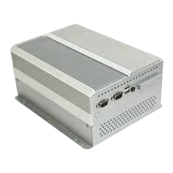
1.5 Brief Description of the ACS-2675C The ACS-2675C is a Fan-less High-efficiency Thermal Solution and ultra-compact standalone Box PC, powered by an Intel Core 2 Duo with 45nm, up to P8600 2.4GHz, and supporting 6 x USB 2.0 ports, 4 x COM Ports, 1 x VGA, 1 x HDMI, support PCI or PCIe Expansion, 2 x SATA HDD space, 1 x external CF slot, 9-32V wide-ranging power input etc. -
Page 11: Chapter 2 Hardware
Chapter 2 Hardware 2.1 Mainboard Figure 2.1: Mainboard Dimensions ACS-2675C User Manual... -
Page 12: Installations
2.2 Installations ASB-M801 is a Mini-ITX industrial motherboard developed on the basis of Intel GM45 and ICH9M, which provides abundant peripheral interfaces to meet the needs of different customers. Also, it features dual 1000M LAN port, 6-COM port and one Mini PCIE configuration. To satisfy the special needs of high-end customers, PC104+ port (capable of adjusting IO voltage) richer extension functions. -
Page 13: Figure 2.3: Jumpers And Connectors Location_ Board Bottom
Figure 2.3: Jumpers and Connectors Location_ Board Bottom 1. JP2: (2.0mm Pitch 1X2 Pin Header),ATX Power and Auto Power on jumper setting. Mode Open ATX Power Close Auto Power on (Default) 2. RTC/SRTC: (2.0mm Pitch 1X2 Pin Header)CMOS clear jumper, CMOS clear operation will permanently reset old BIOS settings to factory defaults. - Page 14 Open NORMAL (Default) Close 1-2 Clear CMOS Procedures of CMOS clear: a) Turn off the system and unplug the power cord from the power outlet. b) To clear the CMOS settings, use the jumper cap to close pins1 and 2 for about 3 seconds then reinstall the jumper clip back to pins open.
- Page 15 DCIN ATX12V input output (Default) DC9~32V DC 12V 5. ATX12V: (2x2 Pin Connector),DC12V System power output connector. Power Pin# output Pin1 Ground Pin2 Ground Pin3 DC+12V Pin4 DC+12V 6. ATX (option): (2.0mm Pitch 1X3 box Pin Header), connect PSON and 5VSB and Ground signal,support ATX Power model.
- Page 16 8. CPU_FAN1/SYS_FAN1: (2.54mm Pitch 1x3 Pin Header),Fan connector, cooling fans can be connected directly for use. You may set the rotation condition of cooling fan in menu of BIOS CMOS Setup. Pin# Signal Name Ground Rotation detection Note: Output power of cooling fan must be limited under 5W. 9.
- Page 17 CRT_V_SYNC CRT_DDCCL 12. INVERTER1: (2.0mm Pitch 1x6 box Pin Header), Backlight control connector for LVDS1. Pin# Signal Name +DC12V +DC12V Ground Ground BKLT_EN BKLT_CTRL Note: Pin6 is backlight control signal, support DC or PWM mode, mode select at BIOS CMOS menu.
- Page 18 LB_D2_P LA_D2_P Ground Ground LB_CLK_N LA_CLK_N LB_CLK_P LA_CLK_P Ground Ground DS_DDC_DATA LVDS_DOC_CLK Ground Ground LB_D3_N LA_D3_N LB_D3_P LA_D3_P 14. HDMI: (HDMI 19P Connector), High Definition Multimedia Interface connector. 15. BT1: POWER on/off Button, They are used to connect power switch button. The two pins are disconnected under normal condition.
- Page 19 Pin# Signal Name DCD# (Data Carrier Detect) RXD (Received Data) TXD (Transmit Data) DTR (Data Terminal Ready) Ground DSR (Data Set Ready) RTS (Request To Send) CTS (Clear To Send) JCOM1 select Setting 18. COM2: (Type DB9),Rear serial port, standard DB9 Male serial port is provided to make a direct connection to serial devices.
- Page 20 Ground 20. JCOM6: (2.0mm Pitch 1x3 Pin Header) COM6 setting jumper, pin 1~3 are used to select signal out of pin 10 of COM6 port. JP1 Pin# Function Close 1-2 COM5 Pin10=+5V (default) Close 2-3 COM5 Pin10=+12V (option) 21. COM6: (2.0mm Pitch 2X5 Pin Header), COM6 Port, standard RS232 ports are provided.
- Page 21 respectively located at the left-hand and right-hand side of the Ethernet port indicate the activity and transmission state of LAN. 24. JACK1: (Diameter 3.5mm Double stack Jack), HD Audio port, An onboard Realtek ALC662 codec is used to provide high quality audio I/O ports. Line Out can be connected to a headphone or amplifier, MIC is the port for microphone input audio.
- Page 22 for PCI-104 Plus devices. The default for this jumper is “all open”, meaning the user must select the voltage to be used. JP_104P Pin# PC104+ VIO Voltage All Open Default Close 1-2 +3.3V PCI Card Close 2-3 +5V PCI Card 28.
- Page 23 ports or one RS485 port, three USB ports, one power led, one power button, via a dedicated cable connected to TB-522 MIO1. Functio Signal Name Pin# Pin# Signal Name Function 422RX+ 485+ / 422TX+ COM3 422RX- 485- / 422TX- COM3 RS422 or Ground RS485...
- Page 24 GPIO_IN_4 GPIO_OUT_4 Ground 5V_S5 PS2_K/ PS2_Mous Ps2_KBDATA PS2_MSDATA PS2_KBCLK PS2_MSCLK 5V_USB_23 5V_USB_23 USB2 USB3 USB2_N USB3_N USB2_P USB3_P Ground Ground 5V_USB_01 5V_USB_01 USB0 USB0_N USB1_N USB1 USB0_P USB1_P Ground Ground Pin1-3: HDD LED, They are used to connect hard disk activity LED. The LED blinks when the hard disk is reading or writing data.
- Page 25 via a dedicated USB cable, speed up to 480Mb/s. Note: When connecting LEDs and buzzer and GPIO and USB, pay special attention to the signal polarity. Make sure that the connector pins have a one-to-one correspondence with chassis wiring, or it may cause boot up failure. 34.
- Page 26 up to 3.0Gb/s. (Option): ASB-M801ET/EB: SATA1/SATA2/SATA3 drives supporting RAID 0 or RAID 1 function. MODEL SATA Color RAID ASB-M801T Black: ASB-M801B SATA1/SATA2/SATA3/SATA4 ASB-M801ET Blue: SATA1/SATA2/SATA3 ASB-M801EB Black: SATA4 37. IDE_CF1 (Option): Card socket), it is located at the bottom of the board and serves as an insert interface for Type I and Type II Compact Flash card.
- Page 27 LED2: status. POWER LED PWR BT: POWER on/off Button, They are used to connect power switch button. The two pins are disconnected under normal condition. You may short them temporarily to realize system startup & shutdown or awaken the system from sleep state. PWR LED: status.
- Page 28 Note: Use COM3 RS422 or RS485 Function, please enter BIOS CMOS Setup. Path: BIOS Setup Utility \ Advanced /Super IO Configuration \ Serial Port3 Type: [RS-485] [RS-422] COM4: (Type DB9),Rear serial port, standard DB9 Male serial port is provided to make a direct connection to serial devices.
- Page 29 TB-520P1(option): TB-520P1 connect to ASB-M801T/ET PC104+ connector, PC104+ is located at the top, It provides one PCI slot. 43. TB-520P2: TB-520P1 connect to ASB-M801T/ET PC104+ connector, PC104+ is located at the top, It provides two PCI slots. 44. TB-520P1E1: TB-520P1E1 connect to ASB-M801T/ET PC104+ and PCIEX2 connector,PC104+ and PCIEX2 are located at the top, It provides one PCI slot and one PCIE slot.
- Page 30 45. TB-521P1: TB-521P1 connect to ASB-M801B/EB PC104+ connector, PC104+ is located at the Bottom, It provides one PCI slot. 46. TB-521P2: TB-521P2 connect to ASB-M801B/EB PC104+ connector, PC104+ is located at the Bottom, It provides two PCI slots. ACS-2675C User Manual...
- Page 31 47. TB-521P1E1: TB-521P1E1 connect to ASB-M801B/EB PC104+ and PCIEX2 connector,PC104+ and PCIEX2 are located at the Bottom, It provides one PCI slot and one PCIE slot. ACS-2675C User Manual...
-
Page 32: Chapter 3 Bios Setup
Chapter 3 BIOS Setup 3.1 Operations after POST Screen After CMOS discharge or BIOS flashing operation, the system will display the following screen for your further operation. Press F2 key to continue or F1 key to enter CMOS Setup. AMIBIOS© 2006 American Mega trends , Inc. BIOS Date: 05/13/11 22:54:20 Ver: 08.00.15 CPU : Genuine Intel(R) CPU @ 2.00GHz... -
Page 33: Bios Setup Utility
3.2 BIOS SETUP UTILITY Press [Del] key to enter BIOS Setup utility during POST, and then a main menu containing system summary information will appear. BIOS SETUP UTILITY Main Advanced PCIPnP Boot Security Chipset Exit User [ENTER],[TAB] System Overview or [SHIFT-TAB] to AMIBIOS Version : 08.00.15... -
Page 34: Advanced Settings
System Time [00:02:28] General Help System Date [Tue 05/13/2011] F10 Save and Exit ESC Exit V02.61 © Copyright 1985-2006 American Mega trends , Inc. System Time: Set the system time, the time format is: Hour : 0 to 23 Minute : 0 to 59 Second : 0 to 59 System Date:... - Page 35 ↑↓ Select Item Enter Charge Field General Help Save and Exit Exit V02.61 © Copyright 1985-2006 American Mega trends , Inc. 3.4.1 CPU Configuration BIOS SETUP UTILITY Advanced For UP platforms, Configure advanced CPU settings Leave it enabled. Module Version: 3F.10 For DP/MP serves, Manufacturer : Intel It may use to tune...
- Page 36 [Enabled] [Disabled] Max CPUID Value Limit: [Disabled] [Enabled] Execute-Disable Bit Capability: [Enabled] [Disabled] Intel(R) C-STATE tech: [Disabled] [Enabled] 3.4.2 IDE Configuration BIOS SETUP UTILITY Advanced Disabled IDE Configuration SATA#1 Configuration [Compatible] Compatible Configure SATA as [IDE] Enhanced SATA#1 Configuration [Enhanced] ►...
- Page 37 ATA(PI) 80Pin Cable Detection [Host & Device] V02.61 © Copyright 1985-2006 American Mega trends , Inc. SATA#1 Configuration: [Compatible] [Disabled] [Enhanced] Configure SATA as: [IDE] [RAID] [AHCI] SATA#2 Configuration: [Enhanced] [Disabled] Hard Disk Write Protect: [Disabled] [Enabled] IDE Detect Time Out : [35] [10] [15]...
- Page 38 BIOS SETUP UTILITY Advanced Allow BIOS to Select Configure Win627UHG Super IO Chipset Serial Port1 Address [3F8] Serial Port Base Serial Port2 Address [2F8] Address. Serial Port3 Address [3E8] Serial Port3 IRQ [IRQ4] Serial Port3 Mode [RS-485] Serial Port4 Address [2E8] Serial Port4 IRQ [IRQ3]...
-
Page 39: System Temperature
70℃/158℉ Vcore :1.064V AVCC :5.058V 5VCC :5.067 V 3.3V :3.264 V 5.0V :5.029 V :12.042 V :5.058 V ← Select Screen VBAT :3.366 V ↑↓ Select Item +- Charge Field Smart Fan Configuration F1 General Help Maximum CPU Temperature [60℃/140℉] F10 Save and Exit Maximum PWM Duty for CPU Fan [60%] ESC Exit... - Page 40 ACPI Version Features: [ACPI V1.0] [ACPI V2.0] [ACPI V3.0] ACPI APIC support: [Enabled] [Disabled] AMI OEMB table: [Enabled] [Disabled] Headless mode: [Disabled] [Enabled] [Chipset ACPI Configuration]: APIC ACPI SCI IRQ: [Disabled] [Enabled] High Performance Event Timer: [Disabled] [Enabled] 3.4.6 AHCI Configuration BIOS SETUP UTILITY Advanced Enables For supporting...
-
Page 41: Mps Configuration
► AHCI Port2 [Not Detected] ► AHCI Port3 [Not Detected] ► AHCI Port4 [Not Detected] ← Select Screen ► AHCI Port5 [Not Detected] ↑↓ Select Item Enter Go to sub screen General Help Save and Exit ESC Exit V02.61 © Copyright 1985-2006 American Mega trends , Inc. While entering setup, BIOS auto detects the presence of IDE devices. -
Page 42: Smbios Configuration
PCI Express L0s and Active State Power -Management L1 Link Power [Disabled] States. ← Select Screen ↑↓ Select Item Charge Field General Help F10 Save and Exit ESC Exit V02.61 © Copyright 1985-2006 American Mega trends , Inc. Active State Power Management: [Disabled] [Enabled] 3.4.9 Smbios Configuration... -
Page 43: Advanced Pci/Pnp Settings
3.4.10 USB Configuration BIOS SETUP UTILITY Advanced Enables support for USB Configuration Module Version – 2.24.3-13.4 legacy USB.ATUO option disables legacy USB Devices Enabled : support if no USB 1Keyboard devices are connected Legacy USB Support [Enabled] USB2.0 Controller Mode [Fullspeed] BIOS EHCI Hand-Off [Enabled]... - Page 44 BIOS SETUP UTILITY Main Advanced PCIPNP Boot Security Chipset Exit Clear NURAM during Advanced PCI/PnP Settings System Boot. WARNING: Setting wrong values In below sections may cause system to malfunction. Clear N VRAM [No] Plug & Play O/S [No] PCI Latency Timer [64] Allocate IRQ to PCI VGA [Yes]...
- Page 45 [32] [96] [128] [160] [192] [224] [248] Allocate IRQ to PCI VGA: [Yes] [No] Palette Snooping: [Disabled] [Enabled] PCI IDE BusMaster: [Disabled] [Enabled] OffBoard PCI/ISA IDE Card: Some PCI IDE cards may require this to be set to the PCI slot number that is holding the card.
-
Page 46: Boot Settings
Reserved: Specified DMA is reserved for use by legacy ISA devices. Reserved Memory Size: Size of memory block to reserve for legacy ISA devices. [Disabled] [16k] [32k] [64k] 3.6 Boot Settings BIOS SETUP UTILITY Main Advanced PCIPnP Boot Security Chipset Exit Configure Settings Boot Settings... - Page 47 Quiet Boot: [Disabled] [Enabled] Disabled: Displays normal POST messages. Enabled: Displays OEM logo instead of POST messages. AddOn ROM Display Mode: Set display mode for Option ROM. [Force BIOS] [Keep Current] Bootup Num-Lock: Select Power-on state for Numlock. [On] [Off] Wait For ‘F1’...
-
Page 48: Security Settings
3.7 Security Settings BIOS SETUP UTILITY Main Advanced PCIPnP Boot Security Chipset Exit Install or Change the Security Settings password. Supervisor Password :Not Installed User Password :Not Installed Change Supervisor Password Change User Password Boot Sector Virus Protection [Disabled] ← Select Screen ↑↓... -
Page 49: Advanced Chipset Settings
clear all previously typed CMOS passwords. You will be requested to confirm the password. Type the password again and press Enter key. You may press Esc key to abandon password entry operation. To clear the password, just press Enter key when password input window pops up. -
Page 50: North Bridge Configuration
Note: Due to limited address length of BIOS, only a portion of panel parameters are listed in BIOS Setup. If the connected panel is not included in the parameter list, display problem will occur. In this case, Please do not change BIOS setup. - Page 51 [PCI/IGD] [IGD] IGD Graphics Mode Select: [Enabled, 64MB] [Disabled] [Enabled, 32MB] [Enabled, 128MB] Video Function Configuration: BIOS SETUP UTILITY Chipset Options Video Function Configuration DVMT Mode Select [DVMT Fixed Mode Mode] DVMT Mode DVMT/FIXED Memory [256MB] Boot Display Device [VBIOS-Default] Flat Panel Type [1024x768 18bit 1c]...
- Page 52 [DVMT Mode] [FIXED Mode] DVMT/FIXED Memory Size: [256MB] [128MB] [Maximum DVMT] Boot Display Device: [VBIOS-Default] [CRT] [HDMI] [CRT + HDMI] [LVDS] [CRT + LVDS] Flat Panel Type: [1024x 768 18bit 1ch] [640x480 18bit 1ch] [800x480 18bit 1ch] [800x600 18bit 1ch] [1280x800 18bit 1ch] [1366x768 18bit 1ch] [1024x768 24bit 2ch]...
- Page 53 [Level3] [Level4] [Level6] [Level7] [Level9] [Level10] [Level11] [Level12] [Level13] [Level14] [Level15] Note: Panel support PWM Function. Backlight Control Mode: [DC] [PWM] Backlight Image Adaptation: [VBIOS-Default] [BIA Disabled] [BIA Enabled at Level1] [BIA Enabled at Level2] [BIA Enabled at Level3] [BIA Enabled at Level4] [BIA Enabled at Level5] 3.8.2 South Bridge Configuration: BIOS SETUP UTILITY...
- Page 54 SLP_S4# Min. Assertion Width [4 to 5 Seconds] Restore on AC Power loss [Power off] PCIE Ports Configuration PCIE Port 0 [Auto] ← Select Screen PCIE Port 1 [Auto] ↑↓ Select Item PCIE Port 2 [Auto] +- Charge Field F1 General Help PCIE Port 3 [Auto] F10 Save and Exit...
- Page 55 SLP_S4# Min. Assertion Width: [4 to 5 Seconds] [3 to 4 Seconds] [2 to 3 Seconds] [1 to 2 Seconds] Restore on AC Power Loss: [Power Off] [Power On] [Last Status] PCIE Ports Configuration: PCIE Port 0: [Auto] [Enabled] [Disabled] PCIE Port 1: [Auto] [Enabled]...
-
Page 56: Exit Options
[Port2] [Port3] [Port4] [Port5] PCIE Port 0 IOxAPIC Enabled: PCIE Port 1 IOxAPIC Enabled: PCIE Port 2 IOxAPIC Enabled: PCIE Port3 IOxAPIC Enabled: PCIE Port4 IOxAPIC Enabled: PCIE Port5 IOxAPIC Enabled: [Disabled] [Enabled] Exit Options BIOS SETUP UTILITY Main Advanced PCIPnP Boot Security... -
Page 57: Discard Changes
Save configuration changes and exit setup? F10 key can be used for this operation) [OK] [Cancel] Discard Changes and Exit: Discard Changes and Exit setup? ESC key can be used for this operation) [OK] [Cancel] Discard Changes: Discard changes? F7 key can be used for this operation) [OK] [Cancel] Load Optimal Defaults:... -
Page 58: Chapter 4 Installation Of Drivers
Chapter 4 Installation of Drivers This chapter describes the installation procedures for software and drivers under the windows XP. The software and drivers are included with the motherboard. The contents include Intel chipset driver VGA driver LAN drivers Audio driver .NET framework 3.5 driver Installation instructions are given below. -
Page 59: Intel Chipset Driver
4.1 Intel Chipset Driver To install the Intel chipset driver, please follow the steps below. Step 1: Select Chipset from the list Follow the step-by-step installation process to install the driver. ACS-2675C User Manual... - Page 60 ACS-2675C User Manual...
- Page 61 Click Finish, when the installation process is complete, the Setup Complete screen appears. See as picture. ACS-2675C User Manual...
-
Page 62: Intel Graphics Media Accelerator Driver
4.2 Intel Graphics Media Accelerator driver To install the VGA drivers, follow the steps below to proceed with the installation. 1. Click Intel(R) GM45 Chipset Family Graphics Driver. Follow the step-by-step installation process to install the Graphics Media Accelerator driver. ACS-2675C User Manual... - Page 63 ACS-2675C User Manual...
- Page 64 ACS-2675C User Manual...
- Page 65 Click FINISH; A Driver Installation Complete. ACS-2675C User Manual...
-
Page 66: Intel 82574L Lan Device Driver
4.3 Intel 82574L LAN Device Driver To install the Intel R 82574L Gigabit LAN connect device driver, please follow the steps below. Select LAN from the list Follow the step-by-step installation process to install the LAN driver. ACS-2675C User Manual... - Page 67 ACS-2675C User Manual...
- Page 68 Click FINISH; A Driver Installation Complete. ACS-2675C User Manual...
-
Page 69: Realtek Alc662 Hd Audio Driver Installation
4.4 Realtek ALC662 HD Audio Driver Installation To install the Realtek High Definition (HD) Audio driver, please follow the steps below. Select Audio from the list Follow the step-by-step installation process to install the Realtek HD Audio driver. ACS-2675C User Manual... - Page 70 Click FINISH; A Driver Installation Complete. ACS-2675C User Manual...
-
Page 71: Microsoft .Net Framework 3.5 Service Installation
4.5 Microsoft .NET Framework 3.5 Service Installation To install the Microsoft .NET Framework 3.5 Service, please follow the steps below. ACS-2675C User Manual... - Page 72 ACS-2675C User Manual...
- Page 73 ACS-2675C User Manual...
Need help?
Do you have a question about the ACS-2675C Box PC and is the answer not in the manual?
Questions and answers