Table of Contents
Advertisement
Quick Links
ACS-2180
th
Intel 4
Gen. Core i3 Ultra Slim Fanless Box PC
User Manual
Release Date
Revision
Sep. 2015
V1.0
®2015 Aplex Technology, Inc.
All Rights Reserved.
Published in Taiwan
Aplex Technology, Inc.
15F-1, No.186, Jian Yi Road, Zhonghe District, New Taipei City 235, Taiwan
Tel: 886-2-82262881 Fax: 886-2-82262883 E-mail:
aplex@aplex.com.tw
URL:
www.aplextec.com
Advertisement
Table of Contents

Related Manuals for Aplex ACS-2180


Summary of Contents for Aplex ACS-2180
-
Page 1: User Manual
Gen. Core i3 Ultra Slim Fanless Box PC User Manual Release Date Revision Sep. 2015 V1.0 ®2015 Aplex Technology, Inc. All Rights Reserved. Published in Taiwan Aplex Technology, Inc. 15F-1, No.186, Jian Yi Road, Zhonghe District, New Taipei City 235, Taiwan Tel: 886-2-82262881 Fax: 886-2-82262883 E-mail: aplex@aplex.com.tw... -
Page 2: Revision History
Revision History Reversion Date Description 2015/09/21 Official Version ACS-2180 User Manual... -
Page 3: Warning!/Caution/Disclaimer
This information in this document is subject to change without notice. In no event shall Aplex Technology Inc. be liable for damages of any kind, whether incidental or consequential, arising from either the use or misuse of information in this document or in any related materials. -
Page 4: Packing List
Packing List Accessories (as ticked) included in this package are: □ Adaptor □ Driver & manual CD disc □ Other.___________________(please specify) ACS-2180 User Manual... -
Page 5: Safety Precautions
Always disconnect power when the system is not in use. ◆ Disconnect power when you change any hardware devices. For instance, when you connect a jumper or install any cards, a surge of power may damage the electronic components or the whole system. ACS-2180 User Manual... -
Page 6: Table Of Contents
Warning!/Caution/Disclaimer......…………………………….……………………2 Packing List…………………………………….…………………………………………………....3 Safety Precautions…………………………………….…………….…..……………………....4 Chapter 1 Getting Started 1.1 Features……..…………………..………………………...…………………………..7 1.2 Specifications…..………………...………………………………………………….7 1.3 Dimensions……..…………………..……………………………………………...8 1.4 Brief Description of ACS-2180………..….…..……………………….……..9 Chapter 2 Hardware 2.1 Mainboard Introduction……………………..…………………………..10 2.2 Specifications…………………………..…………..………………………………10 2.3 Jumpers and Connectors Location……….……………………………...14 2.4 Jumpers Setting and Connectors…………..………………………..……15 Chapter 3 BIOS Setup 3.1 Operations after POST Screen…...……..……...…………………………45... - Page 7 Figures Figure 1.1: Dimensions of ACS-2180……….……….……….…………………………...8 Figure 1.2: Overview of ACS-2180..…………………..……………………………………9 Figure 1.3: I/O side View of ACS-2180…………...………………………………9 Figure 2.1: Motherboard Dimensions…………………………………………………..13 Figure 2.2: Jumpers and Connectors Location-Board Top……………………..14 Figure 2.3: Jumpers and Connectors Location-Board Bottom……………….14 ACS-2180 User Manual...
-
Page 8: Getting Started
Storage Space Storage 1 x SD Card Slot, up to 32GB 1 x 2.5” SATA HDD bay for SATA HDD (Easy Accessible) Expansion Expansion Slot 1 x Mini PCIe Slot (full size) Power Power Input DC 9~36V ACS-2180 User Manual... -
Page 9: Dimensions
Windows Embedded 8.1 Industry Pro, Windows 7 Pro for Embedded, WES7, WE8S Environmental -20~60℃ Operating Temperature -40~85℃ Storage Temperature 10 to 90% @ 40℃, non-condensing Storage Humidity Certification CE / FCC Class A 1.3 Dimensions Figure 1.1: Dimensions of ACS-2180 ACS-2180 User Manual... -
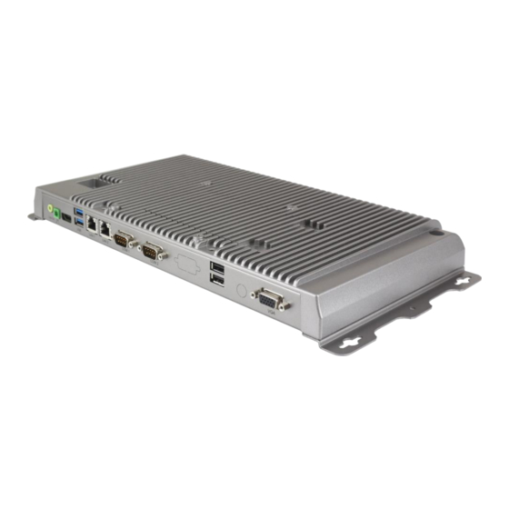
Page 10: Brief Description Of Acs-2180
1.4 Brief Description of ACS-2180 The ACS-2180 is a fanless high-efficiency thermal solution Box PC, powered by Intel Gen. Core i3 CPU built and supporting 4GB DDR3L 1600MHz onboard memory. It comes with 2 x USB 3.0 type A, 2 x USB 2.0 type A, 2 x LAN, 2 x COM ports, 1 x VGA, 1 x Audio jack, 1 x 3-pin DC Power Input Terminal, and 1 x 2-pin connector for power on/off button. -
Page 11: Chapter 2 Hardware
Up to 1920 x 1200 for LVDS (PS8625) Up to 1920 x 1200 for eDP Dual Display HDMI + LVDS Super I/O ITE IT8518E Fintek F81216AD BIOS AMI/UEFI Storage 1 x SATAIII Connector (7P) 1 x SATAIII Connector (7P+15P) ACS-2180 User Manual... - Page 12 1 x PCI-express (CN3) Touch Ctrl 1 x Touch ctrl header for TCH1 (ITE8518E/COM6) (JP4 setting:RS232 or USB 2.0) Power Wide Range DC9V~36V input Management 1 x 3-pin power input connector Switches and 1 x Power on/off switch (BT1/BT2/CN2/CN3) ACS-2180 User Manual...
- Page 13 12V /1.33A (Intel I5-4310U processor with 4GB DDR3L DRAM) Consumption 12V /1.33A (Intel I7-4510U processor with 4GB DDR3L DRAM) EMI/EMS Meet CE/FCC class A 2 x CAN bus TB-528CAN2 1 x SIM Card Socket 1 x mini-PCI-express slot ACS-2180 User Manual...
-
Page 14: Figure 2.1: Motherboard Dimensions
(units :mm) Figure 2.1: Motherboard Dimensions ACS-2180 User Manual... -
Page 15: Jumpers And Connectors Location
2.3 Jumpers and Connectors Location Figure 2.2: Jumpers and Connectors Location- Board Top Figure 2.3: Jumpers and Connectors Location- Board Bottom ACS-2180 User Manual... -
Page 16: Jumpers Setting And Connectors
You may set the rotation condition of cooling fan in menu of BIOS CMOS Setup. Pin# Signal Name Ground Rotation detection Note: Output power of cooling fan must be limited under 5W. 4. U2/U3/U4/U5/U7/U8/U9/U10: (FBGA96) onboard DDR3L Memory. ACS-2180 User Manual... - Page 17 Pin# Signal Name Pin1 VBAT Pin2 Ground 8. JP3: (2.0mm Pitch 1x2 Pin Header) CMOS clear jumper, CMOS clear operation will permanently reset old BIOS settings to factory defaults. CMOS Open NORMAL (Default) Close 1-2 Clear CMOS ACS-2180 User Manual...
- Page 18 Charge voltage 12.6V Charge current 0.5C 10. BAT_LED: (2.0mm Pitch 1x4 Wafer Pin Header), The Charge status indicator for BAT2. Pin1-Pin3: Charge LED status. Pin2-Pin3: Discharge LED status. Pin4-Pin3: EC LED status. Pin# Signal Name Pin1 BAT2_LED+ ACS-2180 User Manual...
- Page 19 LED3: LED STATUS. Green LED for Power status. LED4: LED STATUS. Green LED for Motherboard Standby Power Good status. LED5: LED STATUS. Green LED for CPU1 status 14. HDMI1: (HDMI 19P Connector), High Definition Multimedia Interface connector. ACS-2180 User Manual...
- Page 20 SBC-7110-i54310U-XX 800 x 600 (option) SBC-7110-i74510U-XX 1024 x 768 (option) 1920 x 1080 (option) …… 17. INVT1: (2.0mm Pitch 1x6 wafer Pin Header), Backlight control connector for LVDS. Pin# Signal Name +DC12V_S0 +DC12V_S0 Ground Ground BKLT_EN_OUT BKLT_CTRL ACS-2180 User Manual...
- Page 21 USB7 (JP4 open) USB7 USB7_P USB7_N (JP4 open) 5V_S5_USB 5V_S5_USB Power LED PWR_LED+ Ground Power LED 19. EDP1 (option) Function Signal Name Pin# Pin# Signal Name Function 12V_S0_EDP 12V_S0_EDP 12V_S0_EDP 12V_S0_EDP Ground Ground EDP_VDD5 EDP_VDD5 EDP_VDD3 EDP_VDD3 ACS-2180 User Manual...
- Page 22 (2.0mm Pitch 2x2 wafer Pin Header), USB3(CN1) or Touch jumper setting. Function USB7 (CN1) Touch (TCH1) Close 3-4 (default) Open 3-4 (option) Open 1-2 (default) 21. TCH1: (2.0mm Pitch 1x6 wafer Pin Header), internal Touch controller connector. Pin# Signal Name SENSE GND_EARCH ACS-2180 User Manual...
- Page 23 COM1 port is controlled by pins No. 1~6 of JP1, select output Signal RI or 5V or 12V, For details, please refer to description of JP1 and S_232 and S_422 setting. ACS-2180 User Manual...
- Page 24 BIOS Setup: Advanced/F81216 Super IO Configuration/Serial Port 0 Configuration 【RS-232】 RS422 (option) Pin# Signal Name 422_RX+ 422_RX- 422_TX- 422_TX+ Ground BIOS Setup: Advanced/F81216 Super IO Configuration/Serial Port 0 Configuration 【RS-422】 RS485 (option) Pin# Signal Name 485- 485+ Ground ACS-2180 User Manual...
- Page 25 DSR (Data Set Ready) RTS (Request To Send) CTS (Clear To Send) JP2 select Setting (RI/5V/12V) 29. SATA_P: (2.5mm Pitch 1x2 box Pin Header), One onboard 5V output connector are reserved to provide power for SATA devices. ACS-2180 User Manual...
- Page 26 Line In is used for the connection of external audio source via a Line in cable. MIC is the port for microphone input audio. Signal Name Pin# Pin# Signal Name GND_AUD LINE-OUT-L LINE-OUT-R FRONT_JD LINE1_JD LINE-IN-L LINE-IN-R ACS-2180 User Manual...
- Page 27 Ethernet port indicate the activity and transmission state of LAN. 39. BUZ1: Onboard buzzer. 40. CN2: (DF13-30P Connector), For expand output connector, It provides eight GPIO, one RS422 or RS485, one USB2.0, one Power on/off, one Reset. ACS-2180 User Manual...
- Page 28 Advanced/Super IO Configuration/Serial Port 1 Configuration【RS-422】 Advanced/Super IO Configuration/Serial Port 1 Configuration【RS-485】 41. EC_GPIO: (2.0mm Pitch 1x10 Pin Header), For expand connector, It provides eight GPIO. Pin# Signal Name Ground EC_GPIO1 EC_GPIO2 EC_GPIO3 EC_GPIO4 EC_GPIO5 EC_GPIO6 EC_GPIO7 EC_GPIO8 3.3V_ALLS_EC ACS-2180 User Manual...
- Page 29 PCH_GPIO58 GPIO58 GPIO56 PCH_GPIO57 PCH_GPIO59 GPIO59 GPIO57 Ground Ground PCIE1_TX_N0 PE1_TX_P0 PCIE1_RX_N0 PE1_RX_P0 PCIE PCIE Ground Ground CLK_100M_PE1_N CLK_100M_PE1_P PCIE1_WAKE_N PLT_RST_BUF2- SMB_CLK_S5 SMB_DATA_S5 SMBUS SMBUS CLKREQ_PE1- Ground PCIE 3P3V_S5 PWRBTN_ON- Power Auto on 3P3V_S5 3P3V_S5 12V_S0 12V_S0 ACS-2180 User Manual...
- Page 30 Signal Name Function support PCIe 1X USB2.0 (USB2) SMBus H1/H2: MPCIE1 SCREW HOLES, H2 for mini PCIE card (30mm x 30mm) assemble. H1 for mini PCIE card (30mm x 50.95mm) assemble. LED1: Mini PCIe devices LED Status. ACS-2180 User Manual...
- Page 31 (2.0mm Pitch 2x5 Pin Header), Front USB connector, it provides one USB port via a dedicated USB cable, speed up to 480Mb/s. Signal Name Pin# Pin# Signal Name 5V_USB23 5V_USB23 USB4_N USB3_N (option, NC) USB4_P USB3_P (option, NC) Ground Ground Ground ACS-2180 User Manual...
- Page 32 TXD (Transmit Data) DTR (Data Terminal Ready) Ground DSR (Data Set Ready) RTS (Request To Send) CTS (Clear To Send) JP5 Setting: Pin1-2: RI (Ring Indicator) (default) Pin3-4: 5V Standby power (option) Pin5-6: 12V Standby power (option) ACS-2180 User Manual...
- Page 33 Pin5-6: 12V Standby power (option) COM_6 (option): (2.0mm Pitch 2x5 Pin Header), COM4 Port, up to one standard RS232 port are provided. They can be used directly via COM cable connection. Signal Name Pin# Pin# Signal Name ACS-2180 User Manual...
- Page 34 Mini PCIe devices LED Status. PS2: (2.0mm Pitch 1x6 Pin Wafer), PS/2 keyboard and mouse port, the port can be connected to PS/2 keyboard or mouse via a dedicated cable for direct used. Pin# Signal Name KBDATA MSDATA Ground KBCLK MSCLK ACS-2180 User Manual...
- Page 35 (Type DB9), serial port, standard DB9 serial port is provided to make a direct connection to serial devices. COM3 port is controlled by pins No.1~6 of JP5, select output Signal RI or 5V or 12v, for details, please refer to description of JP5. ACS-2180 User Manual...
- Page 36 TXD (Transmit Data) DTR (Data Terminal Ready) Ground DSR (Data Set Ready) RTS (Request To Send) CTS (Clear To Send) JP6 Setting: Pin1-2: RI (Ring Indicator) (default) Pin3-4: 5V Standby power (option) Pin5-6: 12V Standby power (option) ACS-2180 User Manual...
- Page 37 (Socket 52Pin), mini PCIe socket, it is located at the top, it supports mini PCIe devices with Smbus, SIM and PCIe signal. MPCIe card size is 30x30mm or 30x50.95mm. Signal Name Function support PCIe 1X USB2.0 (USB3) NC (option) SMBus ACS-2180 User Manual...
- Page 38 PS/2 keyboard or mouse via a dedicated cable for direct used. Pin# Signal Name KBDATA MSDATA Ground KBCLK MSCLK GPIO1: (2.0mm Pitch 2x5 Pin Header), General-purpose input/output port, it provides a group of self-programming interfaces to customers for flexible use. Signal Name Pin# Pin# Signal Name Ground ACS-2180 User Manual...
- Page 39 (2.0mm Pitch 2x3 Pin Header), COM3 setting jumper, pin 1~6 are used to select signal out of pin 9 of COM3 port. JP5 Pin# Function Close 1-2 RI (Ring Indicator) (default) Close 3-4 COM3 Pin9: +5V (option) Close 5-6 COM3 Pin9: +12V (option) ACS-2180 User Manual...
- Page 40 Close 5-6 COM_6 Pin9: +12V (option) COM_6: (2.0mm Pitch 2X5 Pin Header), COM4 Port, up to one standard RS232 port are provided. They can be used directly via COM cable connection. Signal Name Pin# Pin# Signal Name ACS-2180 User Manual...
- Page 41 (1.27mm Pitch 2X30 Pin Header), connect to SBC-7110 CN3 pin Header. M-PCIE1: (Socket 52Pin), mini PCIe socket, it is located at the top, it supports mini PCIe devices with Smbus, USB2.0,SIM and PCIe signal. MPCIe card size is 30x30mm or 30x50.95mm. ACS-2180 User Manual...
- Page 42 (2.0mm Pitch 2x5 Pin Header) ,Front USB connector, it provides two USB port via a dedicated USB cable, speed up to 480Mb/s. Signal Name Pin# Pin# Signal Name 5V_USB34 5V_USB34 NC (USB4_N) NC (USB3_N) NC (USB4_P) NC (USB3_P) Ground Ground Ground ACS-2180 User Manual...
- Page 43 COM4 Pin9: +12V (option) COM4: (2.0mm Pitch 2X5 Pin Header), COM4 Port, up to one standard RS232 port are provided. They can be used directly via COM cable connection. Signal Name Pin# Pin# Signal Name Ground JP6 Setting: RI/5V/12V ACS-2180 User Manual...
- Page 44 SMB_CLK_R PCH-GPIO56 PCH-GPIO57 PCH-GPIO59 PCH-GPIO58 JTAG: (2.0mm Pitch 2x5 Pin Header), Reserve. JP1: (2.0mm Pitch 1x2 Pin Header), Reserve. JP2: (2.0mm Pitch 1x2 Pin Header), Reserve. CAN1/CAN2: (3.5mm Pitch 1x10 Pin connector), it provides two CAN-bus Interface. ACS-2180 User Manual...
- Page 45 SBC-7110 Riser Card, TB-528U2 CN3 connect to SBC-7110 CN3 pin Header. TB-528U2 Top: CN3: (1.27mm Pitch 2X30 Pin Header), connect to SBC-7110 CN3 pin Header. USB23(SBC-7110 USB3/USB4): (Double stack USB type A), Rear USB connector, it provides up to 2 USB2.0 ports, speed up to 480Mb/s. ACS-2180 User Manual...
-
Page 46: Bios Setup
BIOS, CPU, memory, and storage devices. 3.2 BIOS Setup Utility Press [Delete] key to enter BIOS Setup utility during POST, and then a main menu containing system summary information will appear. ACS-2180 User Manual... -
Page 47: Main Settings
0 to 59 System Date: Set the system date, the date format is: Day: Note that the ‘Day’ automatically changes when you set the date. Month: 01 to 12 Date: 01 to 31 Year: 1998 to 2099 ACS-2180 User Manual... -
Page 48: Advanced Settings
Enable ACPI Auto Conf: [Disabled] [Enabled] Enable Hibernation: [Enabled] [Disabled] ACPI Sleep State: [S1 only (CPU Stop Clock) ] [S3 (Suspend to RAM)] [Suspend Disabled] [Both S1 and S3 available for OS to choose from] Lock Legacy Resources: [Disabled] [Enabled] ACS-2180 User Manual... - Page 49 Hyper-threading [Enabled] Active Processor Cores [Enabled] Overclocking lock [All] Limit CPUID Maximum [Disabled] Execute Disabled Bit [Enabled] Intel Virtualization Technology [Enabled] Hardware Prefetcher [Enabled] Asjacent Cache Line Prefetch [Enabled] CPU AES [Enabled] Boot Performance mode [Turbo Performance] ACS-2180 User Manual...
- Page 50 Serial ATA Port 0 Empty Software Preserve Unknown Serial ATA Port 1 Empty Software Preserve Unknown ……. 3.4.4 USB Configuration USB Configuration USB Module Version 8.10.31 USB Devices: 1 Keyboard, 1 Mouse, 1 Hubs Legacy USB Support: ACS-2180 User Manual...
- Page 51 [30 sec] [40 sec] Device power-up delay [Auto] [Manual] 3.4.5 Super IO Configuration Super IO chip IT8518/IT8519 Serial Port 0 Configuration (COM5) Device Mode Selection: [RS-485] [RS-422] Serial Port 1 Configuration (COM6) Device Mode Selection: [RS-485] [RS-422] ACS-2180 User Manual...
-
Page 52: Chipset Settings
Serial Port 1 Configuration Change Settings [Auto] Serial Port 2 Configuration Change Settings [Auto] Serial Port 3 Configuration Change Settings [Auto] 3.4.7 Intel (R) 82574L Gigabit Network Configuration-70:B3:D5:E7 3.4.8 Intel (R) 82574L Gigabit Network Configuration-70:B3:D5:E7 3.5 Chipset Settings ACS-2180 User Manual... - Page 53 PCI Express Root Port 4 PCI Express Root Port 5 PCI Express Root Port 6 USB Configuration USB Precondition [Disabled] XHCI Mode XHCI Idle L1 BTCG USB Ports Per-Port Disabled Control [Disabled] Restore AC Power Loss [Power off] ACS-2180 User Manual...
-
Page 54: Boot Settings
CMOS passwords. You will be requested to confirm the password. Type the password again and press Enter key. You may press key to abandon password entry operation. To clear the password, just press Enter key when password input window pops ACS-2180 User Manual... -
Page 55: Security Settings
System, you will be requested to enter the password before system boot and when entering BIOS setup; if Security Option is set to Setup, you will be requested for password for entering BIOS setup. 3.7 Security Settings Setup Prompt Timeout Bootup Numlock State ACS-2180 User Manual... -
Page 56: Save & Exit Settings
[Disabled] [Enabled] Fast Boot [Disabled] [Enabled] Boot Option Priorities Boot Option #1 Sets the system boot order Hard Drive BBS Priorities [SATA PM:*** … ] Boot Option #1 SATA PM:***… ****** Disabled 3.8 Save & Exit Settings ACS-2180 User Manual... - Page 57 Load Previous Values Load Previous Values? [Yes] [No] Restore Defaults Load Optimized Defaults Load optimized Defaults? [Yes] [No] Save user Defaults Save Values as User Defaults Save configuration? [Yes] [No] Restore user Defaults Restore User Defaults Restore User Defaults? [Yes] [No] ACS-2180 User Manual...
-
Page 58: Chapter 4 Installation Of Drivers
USB 3.0 Driver, Intel® MEI Driver Installation instructions are given below. Important Note: After installing your Windows operating system, you must install first the Intel Chipset Software Installation Utility before proceeding with the installation of drivers. ACS-2180 User Manual... -
Page 59: Intel (R) Core Amt Driver
4.1 Intel(R) CORE TM SoC Chipset To install the Intel chipset driver, please follow the steps below. Step 1. Select Intel (R) CORE TM SoC Chipset from the list Step 2. Click Next to setup program. ACS-2180 User Manual... - Page 60 Step 3. Read the license agreement. Click Accept to accept all of the terms of the license agreement. Step 4. Click Install to begin the installation. ACS-2180 User Manual...
-
Page 61: Intel(R) Vga Chipset
Step 5. Click Finish to complete the setup process. 4.2 Intel(R) VGA Chipset To install the VGA drivers, follow the steps below to proceed with the installation. Step 1.Select Intel(R) VGA Chipset from the list. ACS-2180 User Manual... - Page 62 Step 2. Click Automatically run WinSAT and enable the Windows Aero desktop theme(if supported). Click Next. Step 3. Read license agreement. Click Yes. ACS-2180 User Manual...
- Page 63 Step 4. Click Next to continue. Step 5. Click Next to continue. ACS-2180 User Manual...
-
Page 64: Intel(R) Lan Driver
Step 6. Select Yes, I want to restart this computer now. Then click Finish to complete the installation. 4.3 Intel(R) LAN Driver To install the Intel (R) LAN driver, please follow the steps below. Step 1. Select Intel(R) 82574L LAN Driver from the list. ACS-2180 User Manual... - Page 65 Step 2. . Click Next. Step 3. Read license agreement. Click I accept the terms in the license agreement. Click Next. ACS-2180 User Manual...
- Page 66 Step 4. Click Next to continue. Step 5. Click Install to begin the installation. ACS-2180 User Manual...
-
Page 67: Realtek Alc662 Hd Audio Driver
Step 6. Click Finish to exit the wizard. 4.4 Realtek ALC662 HD Audio Driver To install the Realtek ALC662 HD Audio Driver, please follow the steps below. Step 1. Select Realtek AL662 HD Audio Driver from the list ACS-2180 User Manual... - Page 68 Step 2. Click Next to continue. Step 3. Click Yes, I want to restart my computer now. Click Finish to complete the installation. ACS-2180 User Manual...
-
Page 69: Usb 3.0 Driver
4.5 USB 3.0 Driver To install the USB 3.0 Driver, please follow the steps below. Step 1. Select USB 3.0 Driver from the list Step 2. Click Next to continue. ACS-2180 User Manual... - Page 70 Step 3. Read the license agreement. Then click Yes to continue. Step 4. Click Next to continue. ACS-2180 User Manual...
- Page 71 Step 5. Click Next to continue. Step 6. Select Yes, I want to restart this computer now. Then click Finish to complete the installation. ACS-2180 User Manual...
-
Page 72: Intel(R) Mei Driver
4.6 Intel(R) MEI Driver To install the Intel(R) MEI Driver, please follow the steps below. Step 1. Select Intel(R) MEI Driver from the list. Step 2. Click Next to continue. ACS-2180 User Manual... - Page 73 Step 3. Read the License Agreement and then click Yes to continue. Step 4. Click Next to continue. ACS-2180 User Manual...
- Page 74 Step 5. Select Yes, I want to restart this computer now. Then click Finish to complete the installation. ACS-2180 User Manual...
Need help?
Do you have a question about the ACS-2180 and is the answer not in the manual?
Questions and answers