Table of Contents
Advertisement
Quick Links
Advertisement
Table of Contents

Related Manuals for Aplex ACS-2695A


Summary of Contents for Aplex ACS-2695A
- Page 2 Socket G2, 3rd Generation Intel Core i7/i5/i3 BOX PC Release Date Revision Aug. 2014 V1.01 ® 2014 Aplex Technology, Inc. All Rights Reserved. Published in Taiwan Aplex Technology, Inc. 15F-1, No.186, Jian Yi Road, Zhonghe District, New Taipei City 235, Taiwan...
-
Page 3: Warning
This information in this document is subject to change without notice. In no event shall Aplex Technology Inc. be liable for damages of any kind, whether incidental or consequential, arising from either the use or misuse of information in this document or in any related materials. -
Page 4: Packing List
Always disconnect power when the system is not in use. ◆ Disconnect power when you change any hardware devices. For instance, when you connect a jumper or install any cards, a surge of power may damage the electronic components or the whole system. ACS-2695A User Manual... -
Page 5: Table Of Contents
Disclaimer…….…………………………………………………….…………………2 Packing List.......................3 Safety Precautions....................3 Chapter 1 Getting Started 1.1 Specifications………………………...……….………….……...…..6 1.2 Dimensions……………………...…...……………….…………..7 1.3 Brief Description of ACS-2695A……………………………………8 1.4 Installation of HDD..............9 1.5 Installation of PCI Add-on............10 Chapter 2 Hardware Installation 2.1 Mainboard Specifications……………………………….…………11 2.2 Jumpers Setting and Connectors……………………...…………16 Chapter 3 BIOS Setup 3.1 Operations after POST Screen..........30... - Page 6 Figures Figure 1.1: Dimensions of the ACS-2695A………….………………...7 Figure 1.2: Left-front View of ACS-2695A..………………………..8 Figure 1.3: Right-front View of ACS-2695A……….………..……..8 Figure 2.1: Mainboard Dimensions………………...…………………11 Figure 2.2: Jumpers and Connectors Location-TOP……..…...……12 Figure 2.4: Jumpers and Connectors Location- Bottom……………13 ACS-2695A User Manual...
-
Page 7: Getting Started
10%~90%@ 40℃, non-condensing Vibration 5G, 5-500MHz, 3 Axes(with CF or SSD) 0.5G 5-500MHz, 3 Axes(with HDD) Shock 50G Half sine (11 msec. duration)/operation with SSD Drop 92cm (1 Corner, 3 Edge, 6 Surface) Certificate CE / FCC Class A ACS-2695A User Manual... -
Page 8: Dimensions
1.2 Dimensions Figure 1.1: Dimensions of the ACS-2695A ACS-2695A User Manual... -
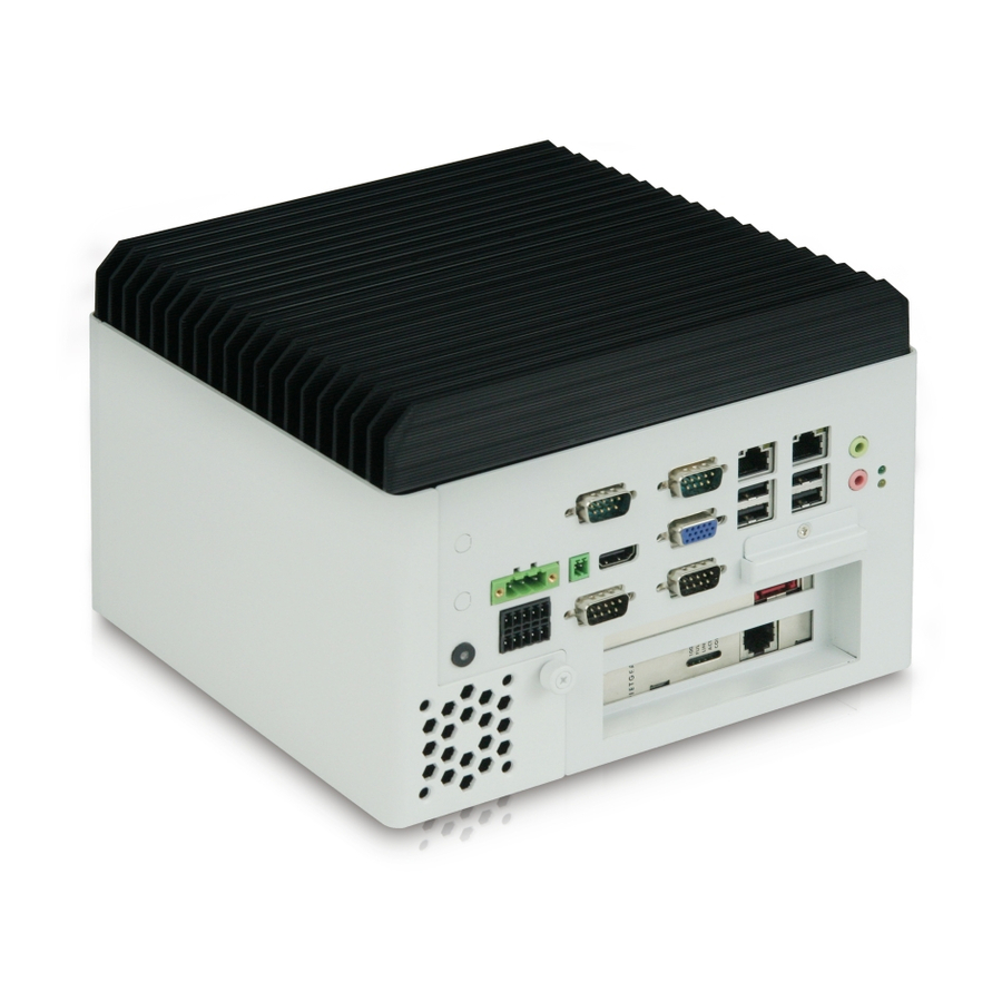
Page 9: Brief Description Of Acs-2695A
Machine Vision, Process Control, Data Terminal, TI, Surveillance, etc. and running factory operations from small visual interface and maintenance applications to large control process applications. The ACS-2695A works very well along with any of our Display series and it absolutely can provide an easy way to perform control and field maintenance. -
Page 10: Installation Of Hdd
HDD bracket as shown in the picture ACS-2695A Loosen screw and draw the HDD bracket out as shown in the picture ACS-2695A Step 3 Tighten the 1 screw as shown in the picture. That’s how it should look after it has been installed. -
Page 11: Installation Of Pci Add-On
** Half Expansion-card limit to be not more than 175mm length Step 3 Tighten the 1 screw as shown in the picture. That’s how it should look after it has been installed. ACS-2695A User Manual... -
Page 12: Chapter 2 Hardware Installation
Chapter 2 Hardware Installation 2.1Mainboard Specifications Figure 2.1: Mainboard Dimensions ACS-2695A User Manual... -
Page 13: Figure 2.2: Jumpers And Connectors Location-Top
Figure 2.2: Jumpers and Connectors Location-TOP ACS-2695A User Manual... -
Page 14: Figure 2.4: Jumpers And Connectors Location- Bottom
Figure 2.3: Jumpers and Connectors Location- Bottom ACS-2695A User Manual... - Page 15 I/O Card TB-523 (option): 1 x 422/485 select header for internal MIO1 (COM3) 1 x RS232/422/485 select header for internal MIO1 (COM4) 8-bit digital I/O by Pin header by MIO2 Digital I/O 4-bit digital Input 4-bit digital Output ACS-2695A User Manual...
- Page 16 Storage: -40℃ to 85℃ 10% - 90%, non-condensing, operating Humidity Power 12V/3.80A (Intel i5-2430M 2.4GHz Processor with 4GB DDR3) 19V/2.0A (Intel i5-2540 2.6GHz Processor with 8GB DDR3) Consumption 19V/2.2A(Intel i7-2620 2.7GHz Processor with 8GB DDR3) EMI/EMS Meet CE/FCC class A ACS-2695A User Manual...
-
Page 17: Jumpers Setting And Connectors
Close 1-2 DC in Power (Default) Close 2-3 ATX 12V_IN Power 4. PS_ON: (2.0mm Pitch 1X2 Pin Header),ATX Power and Auto Power on jumper setting. PS_ON Mode Close 1-2 Auto Power on (Default) Open 1-2 ATX Power ACS-2695A User Manual... - Page 18 (2.0mm Pitch 1X3 box Pin Header), connect PSON and 5VSB and Ground signal,support ATX Power model. Reserved. Pin# Signal Name Pin1 ATX PSON Pin2 ATX Ground Pin3 ATX 5VSB 8. DC_OUT: (2x2 Pin Connector),DC12V and DC5V System power output connector. Pin# Power output ACS-2695A User Manual...
- Page 19 (CRT 2.0mm Pitch 2X5 Pin Header), Video Graphic Array Port, Provide 2x5Pin cable to VGA Port. Signal Name Pin# Pin# Signal Name CRT_RED Ground CRT_GREEN Ground CRT_BLUE Ground CRT_H_SYNC CRT_DDCDATA CRT_V_SYNC CRT_DDCCLK 13. INVT1: (2.0mm Pitch 1x6 box Pin Header), Backlight control connector for LVDS1. ACS-2695A User Manual...
- Page 20 VDD5 Ground Ground VDD33 VDD33 LB_D0_N LA_D0_N LB_D0_P LA_D0_P Ground Ground LB_D1_N LA_D1_N LB_D1_P LA_D1_P Ground Ground LB_D2_N LA_D2_N LB_D2_P LA_D2_P Ground Ground LB_CLK_N LA_CLK_N LB_CLK_P LA_CLK_P Ground Ground VLVDS_DDC_DATA LVDS_DOC_CLK Ground Ground LB_D3_N LA_D3_N LB_D3_P LA_D3_P ACS-2695A User Manual...
- Page 21 (2.0mm Pitch 2x8 Pin Header),COM1 jumper setting, it provides selectable RS232 or RS422 or RS485 serial signal output. Function JP1A Pin# RS232 Close: (Default) Pin1-3, Pin2-4, Pin7-9, Pin8-10, Pin13-14 RS422 Close: (option) Pin3-5, Pin4-6, Pin9-11, Pin10-12, Pin17-18 RS485 Close: (option) Pin3-5, Pin4-6, Pin9-11, Pin10-12, Pin15-16 ACS-2695A User Manual...
- Page 22 DTR (Data Terminal Ready) Ground DSR (Data Set Ready) RTS (Request To Send) CTS (Clear To Send) JP1 select Setting (RI/5V/12V) RS422 (option): Pin# Signal Name 422_R+ 422_R- 422_T- 422_T+ Ground RS485 (option): Pin# Signal Name 485- 485+ Ground ACS-2695A User Manual...
- Page 23 COM cable connection. Signal Name Pin# Pin# Signal Name Ground 24. JP3: (2.0mm Pitch 1x3 Pin Header) COM6 setting jumper, pin 1~6 are used to select signal out of pin 9 of COM6 port. JP3 Pin# Function ACS-2695A User Manual...
- Page 24 LAN. 27. JACK1 (Diameter 3.5mm Double stack Jack), HD Audio port, An onboard Realtek ALC662 codec is used to provide high quality audio I/O ports. Line Out can be connected to a headphone ACS-2695A User Manual...
- Page 25 (4x30 Pin), Riser Card expansion connector. Can expand support one PCIeX16 or two PCIeX8 Signal. ASB-M8771T:PCIE_16X connector in the top. ASB-M8771B:PCIE_16X connector in the Bottom. 34. PCIE1X (option) (4x10 Pin),Riser Card expansion connector.Can expand support two PCIe Signal. ASB-M8771T:PCIE1X connector in the top. ASB-M8771B:PCIE1X connector in the Bottom. ACS-2695A User Manual...
- Page 26 TXD4 COM4 COM4 DSR4- Ground CTS4- RTS4- 5V_S5 RI4- 5V_USB1011 5V_S5 USB10_N USB9_N USB10 USB9 USB10_P USB9_P Ground Ground Ground Ground Power PWR_LED+ 5V_USB1011 USB11_N PWR_LED- USB11 Power MIO_PSON USB11_P Button Ground Ground Power AUTO_PSON- Auto on ACS-2695A User Manual...
- Page 27 The two pins are disconnected under normal condition. You may short them temporarily to realize system startup & shutdown or awaken the system from sleep state. Pin9- Pin10: BUZZER, They are used to connect an external buzzer. ACS-2695A User Manual...
- Page 28 SATA_P2 (2Pin or 4Pin) Pin# Signal Name +DC5V Ground Ground (NC) +DC12V (NC) SATA_P4 (option): Pin# Signal Name (NC) +DC5V (NC) Ground (NC) Ground (NC) +DC12V Note: Output current of the connector must not be above 1A. ACS-2695A User Manual...
- Page 29 47. HS1/HS2/HS3/HS4(CPU SCREW HOLES): CPU FAN SCREW HOLES, Four screw holes for fixed CPU Cooler assemble. 48. H5/H6: U4 SCREW HOLES. 49. TB-526P1: TB-526P1 connect to ASB-M8771B PCIE1X connector, PCIE1X is located at the Bottom, It provides one PCI slot. ACS-2695A User Manual...
- Page 30 ACS-2695A User Manual...
-
Page 31: Bios Setup
BIOS, CPU, memory, and storage devices. 3.2 BIOS Setup Utility Press [Delete] key to enter BIOS Setup utility during POST, and then a main menu containing system summary information will appear. ACS-2695A User Manual... -
Page 32: Main Settings
Second : 0 to 59 System Date: Set the system date, the date format is: Note that the ‘Day’ automatically changes when you set the date. Day: Month: 01 to 12 Date: 01 to 31 Year: 1998 to 2099 ACS-2695A User Manual... -
Page 33: Advanced Settings
PCI Latency Timer: [32 PCI Bus Clocks] [64 PCI Bus Clocks] [96 PCI Bus Clocks] [128 PCI Bus Clocks] [160 PCI Bus Clocks] [192 PCI Bus Clocks] [224 PCI Bus Clocks] [248 PCI Bus Clocks] VGA Palette snoop: ACS-2695A User Manual... - Page 34 Intel(R) Core(TM) i3-3110M CPU @2.40GHz CPU Signature 306a9 Microcode Patch Max CPU Speed 2400 MHz Min CPU Speed 1200Mhz CPU Speed 2400 MHz Processor Cores Intel HT Technology Supported Intel VT-x Technology Supported Intel SMX Technology Not Supported 64-bit Supported ACS-2695A User Manual...
- Page 35 Intel Virtualization Technology [Enabled] [Disabled] Hardware Prefetcher [Enabled] [Disabled] Adjacent Cache Line Prefetch [Enabled] [Disabled] 3.4.4 SATA Configuration SATA Controller(S): [Enabled] [Disabled] SATA Mode Selection: [IDE] [AHCI] [RAID] SATA Test Mode: [Disabled] [Enabled] ISRT Support [Enabled] [Disabled] ACS-2695A User Manual...
- Page 36 ME FW Version ME Firmware Mode ME Firmware Type Full Sku Firmware ME Firmware SKU MDES BIOS Status Code [Disabled] [Enabled] Firmware Update Configuration 3.4.8 Intel(R) Anti-Theft Technology Configuration 3.4.9 AMT Configuration 3.4.10 USB Configuration USB Configuration USB Devices: ACS-2695A User Manual...
- Page 37 Serial Port 3 Configuration Serial Port 4 Configuration Serial Port 5 Configuration Serial Port 6 Configuration 3.4.12 Hardware Monitor PC Health Status System temperature temperature C System Fan Speed CPU Fan Speed 6490 RPM VCORE : +0.816V ACS-2695A User Manual...
- Page 38 CPU PPM Configuration EIST [Enabled] [Disabled] CPU C3 Report [Enabled] [Disabled] CPU C6 report [Enabled] [Disabled] CPU C7 report [Enabled] [Disabled] Long duration power limit Long duration maintained Short duration power limit ACPI T State [Disabled] [Enabled] ACS-2695A User Manual...
-
Page 39: Chipset Settings
System Agent (SA) Configuration System Agent Bridge Name IvyBridge System Agent RC Version 1.6.0.0 VT-d Capability Unsupported ►Graphics Configuration IGFX VBIOS Version 2158 IGFX Frequency 350 MHz Primary Display [Auto] [IGFX] [PEG] [PCI] Internal Graphics [Auto] [Disabled] ACS-2695A User Manual... - Page 40 GFX Low Power Mode [Enabled] [Disabled] Primary IGFX Boot Display [VBIOS Default] [VGA] [DVI] [LVDS] LCD Panel Type [1280 X 1024 24bit 2ch] [640 X 480 18bit 1ch] [800 X 480 18bit 1ch] [800 X 600 18bit 1ch] ACS-2695A User Manual...
- Page 41 [Level 3 ] [Level 4 ] [Level 5 ] [Level 6 ] [Level 7 ] [Level 9 ] [Level 10 ] [Level 11 ] [Level 12 ] [Level 13] [Level 14 ] [Level 15] ►DMI Configuration ►NB PCIe Configuration ACS-2695A User Manual...
- Page 42 ►GT-Power Management Control GT Info GT2 (0X116) RC6 (Render Standby) [Enabled] [Disabled] GT overClocking Support [Disabled] [Enabled] ►PCH-IO Configuration Intel PCH RC Version 1.6.6.0 Intel PCH SKU Name QM77 Intel PCH Rev ID 04/C1 PCH LAN Controller [Disabled] ACS-2695A User Manual...
- Page 43 ►PCI Express Root Port 3 ►PCI Express Root Port 4 ►PCI Express Root Port 5 ►PCI Express Root Port 6 ►PCI Express Root Port 7 ►PCI Express Root Port 8 ►USB Configuration ►PCH Azalia Configuration ►BIOS Security Configuration ACS-2695A User Manual...
-
Page 44: Boot Settings
F4:Save and Exit Exit Version 2.15.1227. Copyright (C) 2012 American Megatrends , Inc. Setup Prompt Timeout Bootup Numlock State [On] [off] Quiet Boot [Disabled] [Enabled] Fast Boot [Disabled] [Enabled] CSM16 Module Verison 07.69 Gatea20 Active [Upon Request] [Always] ACS-2695A User Manual... - Page 45 Option ROM Messages [Force BIOS] [Keep Current] Interrupt 19 Capture [Immediate] [Postponed] Boot Option Priorities ►CSM parameters ACS-2695A User Manual...
-
Page 46: Security Settings
Security Option of Advanced BIOS Features. If Security Option is set to System, you will be requested to enter the password before system boot and when entering BIOS setup; if Security Option is set to Setup, you will be requested for password for entering BIOS setup. ACS-2695A User Manual... -
Page 47: Save & Exit Settings
F4:Save and Exit Exit Version 2.15.1227. Copyright (C) 2012 American Megatrends , Inc. Save Changes and Exit Save & Exit Setup save Configuration and exit ? [Yes] [No] Discard Changes and Ext Exit Without Saving Quit without saving? [Yes] ACS-2695A User Manual... - Page 48 Load Optimized Defaults Load optimized Defaults? [Yes] [No] Save user Defaults Save Values as User Defaults Save configuration? [Yes] [No] Restore user Defaults Restore User Defaults Restore User Defaults? [Yes] [No] Launch EFI Shell from filesystem device WARNING Not Found [ok] ACS-2695A User Manual...
-
Page 49: Chapter 4 Installation Of Drivers
VGA driver, Network Adapter, Audio driver, .USB 3.0 driver, AMT driver. Installation instructions are given below. Important Note: After installing your Windows operating system (Windows XP), you must install first the Intel Chipset Software Installation Utility before proceeding with the installation of drivers. ACS-2695A User Manual... -
Page 50: Intel Chipset Driver
4.1 Intel Chipset Driver To install the Intel chipset driver, please follow the steps below. Step 1: Select Chipset from the list Follow the step-by-step installation process to install the driver. ACS-2695A User Manual... - Page 51 ACS-2695A User Manual...
- Page 52 ACS-2695A User Manual...
- Page 53 ACS-2695A User Manual...
-
Page 54: Intel Vga Chipset Driver
4.2 Intel VGA Chipset Driver To install the VGA drivers, follow the steps below to proceed with the installation. 1. Click Intel VGA Chipset Driver. Follow the step-by-step installation process to install the Graphics Media Accelerator driver. ACS-2695A User Manual... - Page 55 ACS-2695A User Manual...
- Page 56 ACS-2695A User Manual...
- Page 57 Click FINISH; A Driver Installation Complete. ACS-2695A User Manual...
-
Page 58: Intel Network Adapter Driver
4.3 Intel(R) Network Adapter Driver To install the Intel(R) Network Adapter Driver, please follow the steps below. Select LAN from the list Follow the step-by-step installation process to install the LAN driver. ACS-2695A User Manual... - Page 59 ACS-2695A User Manual...
- Page 60 Click FINISH; A Driver Installation Complete. ACS-2695A User Manual...
-
Page 61: Realtek Audio Driver Installation
4.4 Realtek Audio Driver Installation To install the Realtek High Definition (HD) Audio driver, please follow the steps below. Select Audio from the list Follow the step-by-step installation process to install the Realtek HD Audio driver. ACS-2695A User Manual... - Page 62 Click FINISH; A Driver Installation Complete. ACS-2695A User Manual...
-
Page 63: Intel(R) Usb 3.0 Driver Installation
4.5 Intel(R) USB 3.0 Driver Installation To install the Intel(R) USB 3.0 Driver Service, please follow the steps below. ACS-2695A User Manual... - Page 64 ACS-2695A User Manual...
- Page 65 ACS-2695A User Manual...
-
Page 66: Intel(R) Amt Installation
4.6 Intel(R) AMT Installation To install the Intel(R) AMT Service, please follow the steps below. Select AMT Service. ACS-2695A User Manual... - Page 67 ACS-2695A User Manual...
- Page 68 Click FINISH; A Driver Installation Complete. ACS-2695A User Manual...
Need help?
Do you have a question about the ACS-2695A and is the answer not in the manual?
Questions and answers