Table of Contents
Advertisement
Quick Links
ACS-2110 Box PC
User Manual
Release Date
Revision
Nov 2011
V1.0
Jun 2013
V1.1
® 2011 Aplex Technology, Inc.
All Rights Reserved.
Published in Taiwan
Aplex Technology, Inc.
15F-1, No.186, Jian Yi Road, Zhonghe District, New Taipei City 235, Taiwan
Tel: 886-2-82262881 Fax: 886-2-82262883 E-mail:
aplex@aplex.com.tw
URL:
www.aplex.com.tw
ACS-2110 User Manual
1
Advertisement
Table of Contents

Related Manuals for Aplex ACS-2110


Summary of Contents for Aplex ACS-2110
-
Page 1: User Manual
Release Date Revision Nov 2011 V1.0 Jun 2013 V1.1 ® 2011 Aplex Technology, Inc. All Rights Reserved. Published in Taiwan Aplex Technology, Inc. 15F-1, No.186, Jian Yi Road, Zhonghe District, New Taipei City 235, Taiwan Tel: 886-2-82262881 Fax: 886-2-82262883 E-mail: aplex@aplex.com.tw... -
Page 2: Warning
Disclaimer This information in this document is subject to change without notice. In no event shall Aplex Technology Inc. be liable for damages of any kind, whether incidental or consequential, arising from either the use or misuse of information in this document or in any related materials. -
Page 3: Packing List
Always disconnect power when the system is not in use. ◆ Disconnect power when you change any hardware devices. For instance, when you connect a jumper or install any cards, a surge of power may damage the electronic components or the whole system. ACS-2110 User Manual... -
Page 4: Table Of Contents
Table of Contents______________________ Warning!…………………………………………………………………………….……..….2 Disclaimer………………………………………………………………….…………………2 Chapter 1 Getting Started 1.1 Features…..………………….………………………….…………..…...…6 1.2 Specifications………………………………………….………….……...…..6 1.3 Dimensions…………………………………...……………….…………..7 1.4 Brief Description of ACS-2110………..………………….…………………8 Chapter 2 Hardware Installation 2.1 Mainboard Specifications………………………..…………….……………9 2.2 Installations…………………………………………………….……………15 2.3 Onboard Jumpers and Port Pin outs………….…………….……………16 Chapter 3 BIOS Setup 3.1 Operations after POST Screen.............26... - Page 5 4.2 Intel Graphics Media Accelerator Driver...…..…………………..…..59 4.3 Realtek GbE & FE Ethernet PCI-E NIC Driver……....……….63 4.4 Realtek HD Audio Driver Installation…….…………..…………………66 Figures Figure 1.1: Dimensions of the ACS-2110 ……..……………………………...7 Figure 1.2: Front View of ACS-2110…………………..……………………...8 Figure 1.3: Rear View of ACS-2110…..……………………...………………...8 Figure 2.1: Mainboard Overview……………………………………………..…9 Figure 2.2: Mainboard Dimensions……………………………………………10...
-
Page 6: Features
Windows XP, Windows XP Pro, XP Embedded, Windows Embedded Standard 7 Construction Aluminum Molding Heat sink + Heavy Duty steel Chassis Color Black Mounting Wall Mount Dimensions (WxHxD) 232.5(W)x198(H)x48.5(D) mm Net Weight 2kgs 0~50 ゚ C Operating Temperature -20~60 ゚ C Storage Temperature ACS-2110 User Manual... -
Page 7: Dimensions
10~90% @40 ゚ C non-condensing Storage Humidity Certificate CE/FCC Class A 1.3 Dimensions Figure 1.1: Dimensions of the ACS-2110 ACS-2110 User Manual... -
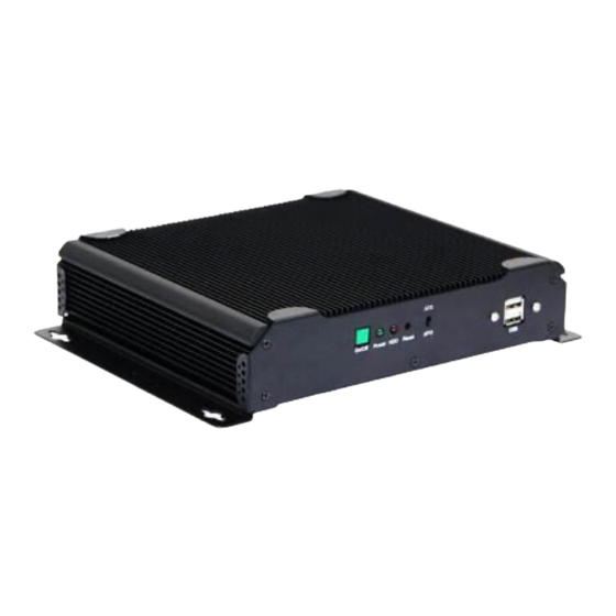
Page 8: Brief Description Of Acs-2110
The ACS-2110 works very well along with any of our Display Monitor series. It absolutely can provide an easy way to perform control and field maintenance. -
Page 9: Mainboard Specifications
Figure 1.3: Rear View of ACS-2110 Chapter 2__________Hardware Installation 2.1 Mainboard Specifications Figure 2.1: Mainboard Overview ACS-2110 User Manual... -
Page 10: Figure 2.2: Mainboard Dimensions
Figure 2.2: Mainboard Dimensions ACS-2110 User Manual... - Page 11 ACS-2110 User Manual...
-
Page 12: Figure 2.3: Connector And Jumper Locations
Figure 2.3: Connector and Jumper Locations ACS-2110 User Manual... - Page 13 Support CR2477 battery by 2-pin header Audio Support Audio via Realtek ALC662 HD audio decoder Support Line-in, Line-out, MIC by 2x5-pin header Printer 1x LPT port by 2x13-pin header Keyboard 1x PS2 keyboard/mouse by 1x6 -pin wafer connector /Mouse ACS-2110 User Manual...
- Page 14 1 x VGA Port Operating: 0 – 60 degree C Temperature Storage: -20 – 80 degree C Humidity 5% - 95%, non-condensing, operating Power 12V @1.4 5A (Intel N270 processor with 1GB DDR2 DRAM) Consumption EMI/EMS CE/FCC class A ACS-2110 User Manual...
-
Page 15: Installations
Insert the SO-DIMM. Push the SO-DIMM chip into the socket at an angle. (See Figure 2.3) Step 4: Open the SO-DIMM socket arms. Gently pull the arms of the SO-DIMM socket out and push the rear of the SO-DIMM down ACS-2110 User Manual... -
Page 16: Onboard Jumpers And Port Pin Outs
4. When entering the POST screen, press the <DEL> key to enter CMOS Setup Utility to load optimal defaults; 5. After the above operations, save changes and exit BIOS Setup. 3. BAT (1.25.0MM 1X2) Battery port: a 3.3V battery is embedded to provide power for CMOS. PIN# Signal Name PIN1 VBAT PIN2 Ground ACS-2110 User Manual... - Page 17 Pin# Signal Name KBDATA MSDATA Ground KBCLK MSCLK 6. LPT (2.0MM 2X13) Parallel port: a standard 26 pin parallel port is provided to connect parallel peripherals as required. Signal Name Pin# Pin# Signal Name PSTB# ACK# ACS-2110 User Manual...
- Page 18 Signal Name Terminal Resistance Terminal Resistance Ground 9. USB4 (2.0MM 2X5) Front USB connector: it provides two USB ports via a dedicated USB adapter cable. Signal Name Pin# Pin# Signal Name USB_P6_DN USB_P7_DN USB_P6_DP USB_P7_DP Ground Ground ACS-2110 User Manual...
- Page 19 2.5' IDE hard disk drivers and supports up to 2 IDE devices. Signal Name Pin# Pin# Signal Name RESET Ground IDE_PDD7 IDE_PDD8 IDE_PDD6 IDE_PDD9 IDE_PDD5 IDE_PDD10 IDE_PDD4 IDE_PDD11 IDE_PDD3 IDE_PDD12 IDE_PDD2 IDE_PDD13 IDE_PDD1 IDE_PDD14 IDE_PDD0 IDE_PDD15 Ground DREQ Ground ACS-2110 User Manual...
- Page 20 PIN9&10: They are used to connect an external buzzer. Note: When connecting LEDs and buzzer, pay special attention to the signal polarity. Make sure that the connector pins have a one-to-one correspondence with chassis wiring, or it may cause boot up failure. ACS-2110 User Manual...
- Page 21 18. FAN (2.54MM 1X3) Fan connector: cooling fans can be connected directly for use. You may set the rotation condition of cooling fan in PC Health Status menu of BIOS Setup. Pin# Signal Name Ground +12V ACS-2110 User Manual...
- Page 22 SPWG. Model name of the interface connector is Hirose DF13-40DP-1.25V. Signal Name Pin# Pin# Signal Name Ground Ground +3.3V +3.3V LADATAN0 LBDATAN0 LADATAP0 LBDATAP0 Ground Ground LADATAN1 LBDATAN1 LADATAP1 LBDATAP1 Ground Ground LADATAN2 LBDATAN2 LADATAP2 LBDATAP2 Ground Ground LACLKN LBCLKN LACLKP LBCLKP Ground Ground LDDC_CLK LDDC_DATA ACS-2110 User Manual...
- Page 23 Pin# Pin# Signal Name Ground Ground +3.3V +3.3V Ground Ground Ground Ground Ground Ground CLK1M CLK2M CLK1P CLK2P Ground Ground SC_DDC SD_DDC Ground Ground 22. BKL2 (2.0MM 1X6) Backlight control connector for LVDS2 Pin# Signal Name +12V ACS-2110 User Manual...
- Page 24 24. SATA1/2 SATA Connectors: two SATA connectors are provided, with transfer speed up to 3.0Gb/s. 25. CN1 (2.5MM 1X2): an onboard 5V output connector is reserved to provide power for IDE/SATA devices. Pin# Signal Name Ground Note: ACS-2110 User Manual...
- Page 25 CF Card Slot: it is located at the backside of the board and serves as an insert interface for Type I and Type II Compact Flash card. The operating voltage of CF card can be set as 3.3V or 5V. The default setting of the product is 3.3V. ACS-2110 User Manual...
-
Page 26: Chapter 3 Bios Setup
CMOS checksum error – Defaults loaded Press to continue, to enter SETUP 11/25/2009-Silverthrone-6A79KAPXC-00 After optimizing and exiting CMOS Setup, the POST screen displayed for the first time is as follows and includes basic information on BIOS, CPU, memory, and storage devices. ACS-2110 User Manual... - Page 27 Enter Boot Menu 11/25/2009-Silverthrone-6A79KAPXC-00 Press F12 key to enter Boot Menu during POST, as shown by the following figure. Boot Menu == Select a Boot First device == + Removable +Hard Disk +CDROM ↑↓:Move Enter:Accept F4:Exit ACS-2110 User Manual...
-
Page 28: Standard Cmos Features
Integrated Peripherals Use this menu to specify your settings for integrated peripherals. Power Management Setup Use this menu to specify your settings for power management. PnP/PCI Configurations This menu is valid only if your system supports PnP/PCI. ACS-2110 User Manual... - Page 29 14 : 31: 6 Menu Level► ►IDE Channel 0 Master Change the [None] ►IDE Channel 0 Slave day, month, [None] ►IDE Channel 1 Master year and [None] ►IDE Channel 1 Slave century [None] Video [EGA/VGA] Halt On [All, But Keyboard] ACS-2110 User Manual...
- Page 30 All Errors Whenever the BIOS detects a non-fatal error, the system boot will stop. All, But Keyboard The system boot will not stop for a keyboard error but stop for all other errors as detected by BIOS. (default) ACS-2110 User Manual...
-
Page 31: Advanced Bios Features
Help F5: Previous Values F6: Fail-Safe Defaults F7: Optimized Defaults CPU Feature The item has the following options: Delay Prior to Thermal [16 Min] (This item allows you to set the duration of entering CPU thermal throttling.) C1E Function [Auto] CPU Power-saving State Enable Control ACS-2110 User Manual... - Page 32 It refers to an advanced interrupt controller mode to meet the requirements of multi-core CPU. MPS Version Control For OS This item is used to specify the multiprocessor specification version of the system. It is recommended to keep the default value (1.4). ACS-2110 User Manual...
- Page 33 Setup utility will not be accessible. Setup (default) If one fails to enter a valid password in the popup box, the system will boot up as usual, but the Setup utility will not be accessible. ACS-2110 User Manual...
-
Page 34: Advanced Chipset Features Setup
↑↓→←:Move Enter:Select +/-/PU/PD:Value F10:Save ESC:Exit F1:General Help F5: Previous Values F6: Fail-Safe Defaults F7: Optimized Defaults Note: If you are not familiar with chipset, never modify these settings at will. DRAM Timing Selectable Two options are available. Manual (Manual setup) ACS-2110 User Manual... - Page 35 If set to Enabled, the feature will enable the caching of video BIOS ROM for better system performance. However, if any program writes into this memory area, it will result in a system error. Options are: Enabled and Disabled. ACS-2110 User Manual...
- Page 36 This feature is to select between LVDS1 and LVDS2. When selecting LVDS panel, users should be informed of LVDS panel types supported by the motherboard. The following options are available: LVDS1 18 800X600 LVDS1 18 1024X768 LVDS1 18*2 1280X1024 LVDS1 18*2 1440X900 LVDS1 18*2 1400X1050 LVDS1 18*2 1600X1200 LVDS1 18 1280X800 ACS-2110 User Manual...
- Page 37 BIOS Setup. If the connected panel is not included in the parameter list, display problem will occur. In this case, we need to adjust BIOS setup. LVDS1 Panel Brightness This feature provides adjustable brightness control: LEVEL3~10. Note: This feature is valid only when the panel supports PWM function. ACS-2110 User Manual...
-
Page 38: Integrated Peripherals
IDE Primary Slave UDMA [Auto] On-Chip Secondary PCI IDE [Enabled] IDE Secondary Master PIO [Auto] IDE Secondary Slave PIO [Auto] IDE Secondary Master UDMA [Auto] IDE Secondary Slave UDMA [Auto] *** On-Chip Serial ATA Setting *** X SATA Mode ACS-2110 User Manual... - Page 39 Ultra DMA/33, Ultra DMA/66 and Ultra DMA/100, select Auto to enable BIOS support. Options are: Auto and Disabled. On-Chip Serial ATA The following five options are available: Disabled (Disable SATA controller) Auto (Allocate SATA/IDE devices automatically) Combined Mode (IDE+SATA Combo Mode) Enhanced Mode ACS-2110 User Manual...
- Page 40 Azalia/AC97 Audio Select [Auto] ↑↓→←:Move Enter:Select +/-/PU/PD:Value F10:Save ESC:Exit F1:General Help F5: Previous Values F6: Fail-Safe Defaults F7: Optimized Defaults USB Controller This item allows you to enable or disable onboard USB controller. Options are: Enabled and ACS-2110 User Manual...
- Page 41 Onboard Serial Port 1 [3F8/IRQ4] Onboard Serial Port 2 [2F8/IRQ3] UART2 Mode Select [Normal] RXD , TXD Active Hi, Lo IR Transmission Delay Enabled UART2 Duplex Mode Half Use IR Pins IR-Rx2Tx2 Onboard Serial Port 3 [3E8/IRQ4] ACS-2110 User Manual...
- Page 42 ASKIR (used as responder infrared port) UR2 Duplex Mode This item will be set to Half Duplex (Half) mode unless your infrared device supports Full Duplex (Full) mode. Power On By PS/2 Keyboard Three options are available: Disabled ACS-2110 User Manual...
- Page 43 Any key Keyboard 98 Watch Dog Timer Select Eight options are available: Disabled, 10Sec, 20Sec, 30Sec, 40Sec, 1Min, 2Min and 4Min ACS-2110 User Manual...
-
Page 44: Power Management Setup
Secondary IDE 0 [Disabled] Secondary IDE 0 [Disabled] FDD,COM,LPT Port [Disabled] PCI PIRQ[A-D]# [Disabled] ↑↓→←:Move Enter:Select +/-/PU/PD:Value F10:Save ESC:Exit F1:General Help F5: Previous Values F6: Fail-Safe Defaults F7: Optimized Defaults PWR Status After PWR Fail Three options are available: ACS-2110 User Manual... - Page 45 Options are: 3, 4, 5, 67, 9, 10, 11 and NA. Suspend Mode When enabled, after the set time of system inactivity, all devices except the CPU will be shut off. Options are: 1/2/4/8/12/20/30/40Min, 1Hour and Disabled. ACS-2110 User Manual...
- Page 46 ** Reload Global Timer Events ** This module contains six modules, all of which are provided with two options: Enable and Disable. If set to Enable, the system will be awakened from sleep status when specific event occurs. ACS-2110 User Manual...
-
Page 47: Pnp/Pci Configurations Setup
PCiEx (PCIE device) Reset Configuration Data Normally, you should set this item to Disabled. If you have installed a new add-on and the system reconfiguration has caused such a serious conflict that the operating system cannot boot up, then ACS-2110 User Manual... - Page 48 This item should be left Disabled. Options are: Enabled and Disabled. ** PCI Express Relative Items ** Maximum Payload Size [128] This item allows you to configure maximum payload size of TLP (Transition Layer Packet). Options are: [128], [256], [512], [1024], [2048] and [4096]. ACS-2110 User Manual...
-
Page 49: Pc Health Status
For example, set CPU Fan Cruise Target to <65℃/149℉> and Fan Cruise Threshold to <±5℃>. When CPU temperature rises to 70℃ (65℃+5℃), the fan will begin to rotate; when CPU temperature drops to 60℃ (65℃-5℃), the fan will stop rotating. ACS-2110 User Manual... -
Page 50: Load Fail-Safe/Optimized Defaults
Load Fail-Safe Defaults (Y/N)?N ►PNP/PCI Configurations Exit Without Saving ►PC Health Status ↑↓→← : Select Item Esc : Quit F10 : Save & Exit Setup Load Fail-Safe Defaults Press Y to load BIOS defaults for stable, but lower performance. ACS-2110 User Manual... - Page 51 Load Optimized Defaults (Y/N)?N ►PNP/PCI Configurations Exit Without Saving ►PC Health Status ↑↓→← : Select Item Esc : Quit F10 : Save & Exit Setup Load Optimized Defaults Press Y to load factory settings delivering optimized performance. ACS-2110 User Manual...
-
Page 52: Set Administrator/User Password
Advanced BIOS Features. If Security Option is set to System, you will be requested to enter the password before system boot and when entering BIOS setup; if Security Option is set to Setup, you will be requested for password for entering BIOS setup. ACS-2110 User Manual... -
Page 53: Save & Exit Setup
Save to CMOS and Exit(Y/N) ? Y ►PC Health Status ↑↓→← : Select Item Esc : Quit F10 : Save & Exit Setup Save Data to CMOS Press Enter key to save the changes and exit from BIOS setup. ACS-2110 User Manual... -
Page 54: Exit Without Saving
Quit Without Saving (Y/N) ? N ►PC Health Status ↑↓→← : Select Item Esc : Quit F10 : Save & Exit Setup Save Data to CMOS Press Y and then Enter key to exit from BIOS setup without saving the changes. ACS-2110 User Manual... -
Page 55: Chapter 4 Installation Of Drivers
VGA driver LAN drivers Audio driver Installation instructions are given below. Important Note: After installing your Windows operating system (Windows XP), you must install first the Intel Chipset Software Installation Utility before proceeding with the installation of drivers. ACS-2110 User Manual... -
Page 56: Intel Chipset Driver
4.1 Intel Chipset Driver To install the Intel chipset driver, please follow the steps below. Step 1: Select Chipset from the list Follow the step-by-step installation process to install the LMS_SQL driver. ACS-2110 User Manual... - Page 57 ACS-2110 User Manual...
- Page 58 ACS-2110 User Manual...
-
Page 59: Intel Graphics Media Accelerator Driver
Click Finish, when the installation process is complete, the Setup Complete screen appears. See as picture. 4.2 Intel Graphics Media Accelerator Driver To install the VGA drivers, follow the steps below to proceed with the installation. 1. Click Intel(R) 945GSE Chipset Family Graphics Driver. ACS-2110 User Manual... - Page 60 Follow the step-by-step installation process to install the Graphics Media Accelerator driver. ACS-2110 User Manual...
- Page 61 ACS-2110 User Manual...
- Page 62 ACS-2110 User Manual...
-
Page 63: Realtek Gbe & Fe Ethernet Pci-E Nic Driver
Click FINISH; A Driver Installation Complete. 4.3 Realtek GbE & FE Ethernet PCI-E NIC Driver To install the Realtek GbE & FE Ethernet PCI-E NIC Driver, please follow the steps below. Select LAN from the list ACS-2110 User Manual... - Page 64 Follow the step-by-step installation process to install the LAN driver. ACS-2110 User Manual...
- Page 65 ACS-2110 User Manual...
-
Page 66: Realtek Hd Audio Driver Installation
Click FINISH; A Driver Installation Complete. 4.4 Realtek HD Audio Driver Installation To install the Realtek High Definition (HD) Audio driver, please follow the steps below. Select Audio from the list ACS-2110 User Manual... - Page 67 Follow the step-by-step installation process to install the Realtek HD Audio driver. ACS-2110 User Manual...
- Page 68 ACS-2110 User Manual...
- Page 69 Click FINISH; A Driver Installation Complete. ACS-2110 User Manual...
Need help?
Do you have a question about the ACS-2110 and is the answer not in the manual?
Questions and answers