Table of Contents
Advertisement
Quick Links
APC-3X95P_R
th
15", 17", 19" Intel 4
Core i3/i5/i7 IP65/69K Stainless
Steel Panel PC
User Manual
Release Date
Revision
Mar. 2015
V1.0
®2015 Aplex Technology, Inc.
All Rights Reserved.
Published in Taiwan
Aplex Technology, Inc.
15F-1, No.186, Jian Yi Road, Zhonghe District, New Taipei City 235, Taiwan
Tel: 886-2-82262881 Fax: 886-2-82262883 E-mail:
aplex@aplex.com.tw
URL:
www.aplextec.com
Advertisement
Table of Contents

Related Manuals for Aplex APC-3X95P_R


Summary of Contents for Aplex APC-3X95P_R
-
Page 1: User Manual
Steel Panel PC User Manual Release Date Revision Mar. 2015 V1.0 ®2015 Aplex Technology, Inc. All Rights Reserved. Published in Taiwan Aplex Technology, Inc. 15F-1, No.186, Jian Yi Road, Zhonghe District, New Taipei City 235, Taiwan Tel: 886-2-82262881 Fax: 886-2-82262883 E-mail: aplex@aplex.com.tw... -
Page 2: Revision History
Revision History Reversion Date Description 2015/03/27 Official Version APC-3X95P_R User Manual... -
Page 3: Warning!/Caution/Disclaimer
This information in this document is subject to change without notice. In no event shall Aplex Technology Inc. be liable for damages of any kind, whether incidental or consequential, arising from either the use or misuse of information in this document or in any related materials. -
Page 4: Packing List
Packing List Accessories (as ticked) included in this package are: □ Adaptor □ Driver & manual CD disc □ Other.___________________(please specify) APC-3X95P_R User Manual... -
Page 5: Safety Precautions
Always disconnect power when the system is not in use. ◆ Disconnect power when you change any hardware devices. For instance, when you connect a jumper or install any cards, a surge of power may damage the electronic components or the whole system. APC-3X95P_R User Manual... -
Page 6: Table Of Contents
4.2 Intel (R) VGA Chipset……………………………………………….……..47 4.3 Intel (R) LAN Driver………..………………………………………..………...50 4.4 Realtek ALC662 HD Audio Driver...………………………………………53 4.5 USB 3.0 Driver…………………………………………………………………….55 4.6 Intel (R) AMT Driver…………………..……………………………………….58 Chapter 5 Touch Screen Installation 5.1 Windows XP/2003/Vista/WIN7 Universal Driver Installation for APC-3X95P_R User Manual... - Page 7 Figure 1.7: Front View of APC-3795P/R…………………………………….12 Figure 1.8: Rear View of APC-3795P/R..…………..……………………….12 Figure 1.9: Front View of APC-3995P/R…………………………………….13 Figure 1.10: Rear View of APC-3995P/R…………………………………...13 Figure 2.1: Mainboard Dimensions……………………………………….….16 Figure 2.2: Jumpers and Connectors Location-Board Top………….17 Figure 2.3: Jumpers and Connectors Location-Board Bottom……17 APC-3X95P_R User Manual...
-
Page 8: Getting Started
1 x M12 8pin for LAN Power 1 x M12 3pin DC Power Storage Space Storage 1 x 2.5” SATA HDD or SSD (easily accessible design) 1 x Internal SD Card slot onboard Expansion Expansion Slot 1 x Mini PCIe half size APC-3X95P_R User Manual... - Page 9 Environmental 0~50 Operating temperature ℃ Extended Temperature ℃ ~ ℃ (with industrial SSD, for 15” and 17” option) -30~70 ℃ Storage temperature Storage humidity 10 to 90% @ 40°C, non- condensing Certification CE / FCC Class A APC-3X95P_R User Manual...
-
Page 10: Dimensions
1.3 Dimensions Figure 1.1: Dimensions of APC-3595P/R Figure 1.2: Dimensions of APC-3795P/R APC-3X95P_R User Manual... -
Page 11: Figure 1.3: Dimensions Of Apc-3995P
Figure 1.3: Dimensions of APC-3995P Figure 1.4: Dimensions of APC-3995R APC-3X95P_R User Manual... -
Page 12: Brief Description Of Apc-3X95P/R
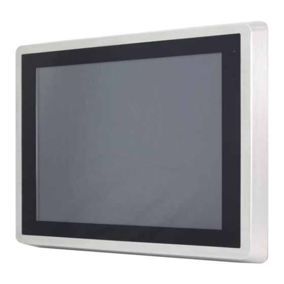
1 x 2.5” SATA HDD or SSD (easily accessible design), and it is 9~36V DC wide-ranging power input. APC-3X95P/3X95R series supports OS such as Windows 7 Professional for Embedded Systems, Windows 7 Ultimate for Embedded Systems and so on. Figure 1.6: Front View of APC-3595P/R Figure 1.7: Rear View of APC-3595P/R APC-3X95P_R User Manual... -
Page 13: Figure 1.7: Front View Of Apc-3795P/R
Figure 1.8: Front View of APC-3795P/R Figure 1.9: Rear View of APC-3795P/R APC-3X95P_R User Manual... -
Page 14: Figure 1.9: Front View Of Apc-3995P/R
Figure 1.10: Front View of APC-3995P/R Figure 1.11: Rear View of APC-3995P/R APC-3X95P_R User Manual... -
Page 15: Chapter 2 Hardware
Up to 1920 x 1200 for LVDS (PS8625) Up to 1920 x 1200 for eDP Dual Display HDMI + LVDS Super I/O ITE IT8518E Fintek F81216AD BIOS AMI/UEFI Storage 1 x SATAIII Connector (7P) 1 x SATAIII Connector (7P+15P) 1 x SD Slot APC-3X95P_R User Manual... - Page 16 1 x Touch ctrl header for TCH1 (ITE8518E/COM6) (JP4 setting:RS232 or USB 2.0) Power Wide Range DC9V~36V input Management 1 x 3-pin power input connector Switches and 1 x Power on/off switch (BT1/BT2/CN2/CN3) LED Indicators 1 x Reset (CN2) APC-3X95P_R User Manual...
-
Page 17: Figure 2.1: Mainboard Dimensions
12V /1.33A (Intel I3-4010U processor with 4GB DDR3L DRAM) Power 12V /1.33A (Intel I5-4310U processor with 4GB DDR3L DRAM) Consumption 12V /1.33A (Intel I7-4510U processor with 4GB DDR3L DRAM) EMI/EMS Meet CE/FCC class A (units :mm) Figure 2.1: Mainboard Dimensions APC-3X95P_R User Manual... -
Page 18: Jumpers And Connectors Location
2.3 Jumpers and Connectors Location Figure 2.2: Jumpers and Connectors Location- Board Top Figure 2.3: Jumpers and Connectors Location- Board Bottom APC-3X95P_R User Manual... -
Page 19: Jumpers Setting And Connectors
You may set the rotation condition of cooling fan in menu of BIOS CMOS Setup. Pin# Signal Name Ground Rotation detection Note: Output power of cooling fan must be limited under 5W. 4. U2/U3/U4/U5/U7/U8/U9/U10: (FBGA96)Onboard DDR3L Memory. Model Memory SBC-7110-i34010P-4G SBC-7110-i54310P-4G APC-3X95P_R User Manual... - Page 20 Power on the system again. d) When entering the POST screen, press the <ESC> or <DEL> key to enter CMOS Setup Utility to load optimal defaults. e) After the above operations, save changes and exit BIOS Setup. APC-3X95P_R User Manual...
- Page 21 Pin2-Pin3: Discharge LED status. Pin4-Pin3: EC LED status. Pin# Signal Name Pin1 BAT2_LED+ Pin2 BAT2_LED- Pin3 Ground Pin4 RST_EC 11. DC_IN1: (5.08mm Pitch 1x3 Pin Connector), DC9V~36V System power input connector. Pin# Signal Name Pin1 DC+9V~36V Pin2 Ground Pin3 APC-3X95P_R User Manual...
- Page 22 (HDMI 19P Connector), High Definition Multimedia Interface connector. 15. JP6: (2.0mm Pitch 2x2 Pin Header),LVDS jumper setting. Function (CN1) Pin1-Pin2 (Close) Signal channel LVDS Pin1-Pin2 (Open) Dual channel LVDS (Default) Pin3-Pin4 (Close) 8/24 bit (Default) Pin3-Pin4 (Open) 6/18 bit APC-3X95P_R User Manual...
- Page 23 24-bit output. Low Voltage Differential Signaling, A high speed, low power data transmission standard used for display connections to LCD panels. Function Signal Name Pin# Pin# Signal Name Function 12V_S0 12V_S0 BKLT_EN_OUT BKLT_CTRL Ground Ground APC-3X95P_R User Manual...
- Page 24 Signal Name Function 12V_S0_EDP 12V_S0_EDP 12V_S0_EDP 12V_S0_EDP Ground Ground EDP_VDD5 EDP_VDD5 EDP_VDD3 EDP_VDD3 Ground Ground EDP_BKLT_EN EDP_TXN_1 EDP_BKLT_CTRL EDP_TXP_1 EDP_VDD_EN Ground EDP_TXN_2 EDP_TXN_0 EDP_TXP_2 EDP_TXP_0 Ground Ground EDP_TXN_3 EDP_AUX_N EDP_TXP_3 EDP_AUX_P EDP_DISP_UTIL 12C1_SCL EDP_HP_CN 12C1_SDA Ground Ground USB7 APC-3X95P_R User Manual...
- Page 25 (2.0mm Pitch 2x3 Pin Header), COM1 jumper setting, pin 1~6 are used to select signal out of pin 9 of COM1 port. JP1 Pin# Function Close 1-2 COM1 RI (Ring Indicator) (default) Close 3-4 COM1 Pin9: DC+5V (option) Close 5-6 COM1 Pin9: DC+12V (option) APC-3X95P_R User Manual...
- Page 26 1~6 of JP1, select output Signal RI or 5V or 12V, For details, please refer to description of JP1 and S_232 and S_422 setting. RS232 (Default) Pin# Signal Name DCD# (Data Carrier Detect) RXD (Received Data) TXD (Transmit Data) DTR (Data Terminal Ready) Ground DSR (Data Set Ready) RTS (Request To Send) APC-3X95P_R User Manual...
- Page 27 RS422 (option) Pin# Signal Name 422_RX+ 422_RX- 422_TX- 422_TX+ Ground BIOS Setup: Advanced/F81216 Super IO Configuration/Serial Port 0 Configuration 【RS-422】 RS485 (option) Pin# Signal Name 485- 485+ Ground BIOS Setup: Advanced/F81216 Super IO Configuration/Serial Port 0 Configuration 【RS-485】 APC-3X95P_R User Manual...
- Page 28 29. SATA_P: (2.5mm Pitch 1x2 box Pin Header), One onboard 5V output connector are reserved to provide power for SATA devices. Pin# Signal Name +DC5V Ground Note: Output current of the connector must not be above 1A. APC-3X95P_R User Manual...
- Page 29 LINE-IN-R MIC-IN-L MIC-IN-R GND_AUD MIC1_JD 36. LINE_OUT: (Diameter 3.5mm Jack), HD Audio port, An onboard Realtek ALC662-VD codec is used to provide high quality audio I/O ports. Line Out can be connected to a headphone or amplifier. APC-3X95P_R User Manual...
- Page 30 (DF13-30P Connector), For expand output connector, It provides eight GPIO, one RS422 or RS485, one USB2.0, one Power on/off, one Reset. Function Signal Name Pin# Pin# Signal Name Function 5V_S5 5V_S5 PCH_GPIO49 GPIO_IN2 GPIO_IN1 PCH_GPIO48 PCH_GPIO51 GPIO_IN4 GPIO_IN3 PCH_GPIO50 APC-3X95P_R User Manual...
- Page 31 Advanced/Super IO Configuration/Serial Port 1 Configuration【RS-422】 Advanced/Super IO Configuration/Serial Port 1 Configuration【RS-485】 41. EC_GPIO: (2.0mm Pitch 1x10 Pin Header), For expand connector, It provides eight GPIO. Pin# Signal Name Ground EC_GPIO1 EC_GPIO2 EC_GPIO3 EC_GPIO4 EC_GPIO5 EC_GPIO6 EC_GPIO7 EC_GPIO8 3.3V_ALLS_EC APC-3X95P_R User Manual...
- Page 32 PCH_GPIO58 GPIO58 GPIO56 PCH_GPIO57 PCH_GPIO59 GPIO59 GPIO57 Ground Ground PCIE1_TX_N0 PE1_TX_P0 PCIE1_RX_N0 PE1_RX_P0 PCIE PCIE Ground Ground CLK_100M_PE1_N CLK_100M_PE1_P PCIE1_WAKE_N PLT_RST_BUF2- SMB_CLK_S5 SMB_DATA_S5 SMBUS SMBUS CLKREQ_PE1- Ground PCIE 3P3V_S5 PWRBTN_ON- Power Auto on 3P3V_S5 3P3V_S5 12V_S0 12V_S0 APC-3X95P_R User Manual...
-
Page 33: Bios Setup
BIOS, CPU, memory, and storage devices. 3.2 BIOS Setup Utility Press [Delete] key to enter BIOS Setup utility during POST, and then a main menu containing system summary information will appear. APC-3X95P_R User Manual... -
Page 34: Main Settings
0 to 59 System Date: Set the system date, the date format is: Day: Note that the ‘Day’ automatically changes when you set the date. Month: 01 to 12 Date: 01 to 31 Year: 1998 to 2099 APC-3X95P_R User Manual... -
Page 35: Advanced Settings
Enable ACPI Auto Conf: [Disabled] [Enabled] Enable Hibernation: [Enabled] [Disabled] ACPI Sleep State: [S1 only (CPU Stop Clock) ] [S3 (Suspend to RAM)] [Suspend Disabled] [Both S1 and S3 available for OS to choose from] Lock Legacy Resources: [Disabled] [Enabled] APC-3X95P_R User Manual... - Page 36 Hyper-threading [Enabled] Active Processor Cores [Enabled] Overclocking lock [All] Limit CPUID Maximum [Disabled] Execute Disabled Bit [Enabled] Intel Virtualization Technology [Enabled] Hardware Prefetcher [Enabled] Asjacent Cache Line Prefetch [Enabled] CPU AES [Enabled] Boot Performance mode [Turbo Performance] APC-3X95P_R User Manual...
- Page 37 Serial ATA Port 0 Empty Software Preserve Unknown Serial ATA Port 1 Empty Software Preserve Unknown ……. 3.4.4 USB Configuration USB Configuration USB Module Version 8.10.31 USB Devices: 1 Keyboard, 1 Mouse, 1 Hubs Legacy USB Support: APC-3X95P_R User Manual...
- Page 38 [30 sec] [40 sec] Device power-up delay [Auto] [Manual] 3.4.5 Super IO Configuration Super IO chip IT8518/IT8519 Serial Port 0 Configuration (COM5) Device Mode Selection: [RS-485] [RS-422] Serial Port 1 Configuration (COM6) Device Mode Selection: [RS-485] [RS-422] APC-3X95P_R User Manual...
-
Page 39: Chipset Settings
Serial Port 1 Configuration Change Settings [Auto] Serial Port 2 Configuration Change Settings [Auto] Serial Port 3 Configuration Change Settings [Auto] 3.4.7 Intel (R) 82574L Gigabit Network Configuration-70:B3:D5:E7 3.4.8 Intel (R) 82574L Gigabit Network Configuration-70:B3:D5:E7 3.5 Chipset Settings APC-3X95P_R User Manual... - Page 40 PCI Express Root Port 4 PCI Express Root Port 5 PCI Express Root Port 6 USB Configuration USB Precondition [Disabled] XHCI Mode XHCI Idle L1 BTCG USB Ports Per-Port Disabled Control [Disabled] Restore AC Power Loss [Power off] APC-3X95P_R User Manual...
-
Page 41: Boot Settings
CMOS passwords. You will be requested to confirm the password. Type the password again and press Enter key. You may press key to abandon password entry operation. To clear the password, just press Enter key when password input window pops APC-3X95P_R User Manual... -
Page 42: Security Settings
System, you will be requested to enter the password before system boot and when entering BIOS setup; if Security Option is set to Setup, you will be requested for password for entering BIOS setup. 3.7 Security Settings Setup Prompt Timeout Bootup Numlock State APC-3X95P_R User Manual... -
Page 43: Save & Exit Settings
[Disabled] [Enabled] Fast Boot [Disabled] [Enabled] Boot Option Priorities Boot Option #1 Sets the system boot order Hard Drive BBS Priorities [SATA PM:*** … ] Boot Option #1 SATA PM:***… ****** Disabled 3.8 Save & Exit Settings APC-3X95P_R User Manual... - Page 44 Load Previous Values Load Previous Values? [Yes] [No] Restore Defaults Load Optimized Defaults Load optimized Defaults? [Yes] [No] Save user Defaults Save Values as User Defaults Save configuration? [Yes] [No] Restore user Defaults Restore User Defaults Restore User Defaults? [Yes] [No] APC-3X95P_R User Manual...
-
Page 45: Chapter 4 Installation Of Drivers
USB 3.0 Driver, Intel® AMT Driver Installation instructions are given below. Important Note: After installing your Windows operating system, you must install first the Intel Chipset Software Installation Utility before proceeding with the installation of drivers. APC-3X95P_R User Manual... -
Page 46: Intel (R) Core Amt Driver
4.1 Intel(R) CORE TM SoC Chipset To install the Intel chipset driver, please follow the steps below. Step 1. Select Intel (R) CORE TM SoC Chipset from the list Step 2. Click Next to setup program. APC-3X95P_R User Manual... - Page 47 Step 3. Read the license agreement. Click Accept to accept all of the terms of the license agreement. Step 4. Click Install to begin the installation. APC-3X95P_R User Manual...
-
Page 48: Intel(R) Vga Chipset
Step 5. Click Finish to complete the setup process. 4.2 Intel(R) VGA Chipset To install the VGA drivers, follow the steps below to proceed with the installation. Step 1.Select Intel(R) VGA Chipset from the list. APC-3X95P_R User Manual... - Page 49 Step 2. Click Automatically run WinSAT and enable the Windows Aero desktop theme(if supported). Click Next. Step 3. Read license agreement. Click Yes. APC-3X95P_R User Manual...
- Page 50 Step 4. Click Next to continue. Step 5. Click Next to continue. APC-3X95P_R User Manual...
-
Page 51: Intel(R) Lan Driver
Step 6. Select Yes, I want to restart this computer now. Then click Finish to complete the installation. 4.3 Intel(R) LAN Driver To install the Intel (R) LAN driver, please follow the steps below. Step 1. Select Intel(R) 82574L LAN Driver from the list. APC-3X95P_R User Manual... - Page 52 Step 2. . Click Next. Step 3. Read license agreement. Click I accept the terms in the license agreement. Click Next. APC-3X95P_R User Manual...
- Page 53 Step 4. Click Next to continue. Step 5. Click Install to begin the installation. APC-3X95P_R User Manual...
-
Page 54: Realtek Alc662 Hd Audio Driver
Step 6. Click Finish to exit the wizard. 4.4 Realtek ALC662 HD Audio Driver To install the Realtek ALC662 HD Audio Driver, please follow the steps below. Step 1. Select Realtek AL662 HD Audio Driver from the list APC-3X95P_R User Manual... - Page 55 Step 2. Click Next to continue. Step 3. Click Yes, I want to restart my computer now. Click Finish to complete the installation. APC-3X95P_R User Manual...
-
Page 56: Usb 3.0 Driver
4.5 USB 3.0 Driver To install the USB 3.0 Driver, please follow the steps below. Step 1. Select USB 3.0 Driver from the list Step 2. Click Next to continue. APC-3X95P_R User Manual... - Page 57 Step 3. Read the license agreement. Then click Yes to continue. Step 4. Click Next to continue. APC-3X95P_R User Manual...
- Page 58 Step 5. Click Next to continue. Step 6. Select Yes, I want to restart this computer now. Then click Finish to complete the installation. APC-3X95P_R User Manual...
-
Page 59: Intel(R) Amt Driver
4.6 Intel(R) AMT Driver To install the Intel(R) AMT Driver, please follow the steps below. Step 1. Select Intel(R) AMT Driver from the list. Step 2. Click Next to continue. APC-3X95P_R User Manual... - Page 60 Step 3. Read the License Agreement and then click Yes to continue. Step 4. Click Next to continue. APC-3X95P_R User Manual...
- Page 61 Step 5. Select Yes, I want to restart this computer now. Then click Finish to complete the installation. APC-3X95P_R User Manual...
-
Page 62: Chapter 5 Touch Screen Installation
If you have an older version of the PenMount Windows WIN7 driver installed in your system, please remove it first. Follow the steps below to install the PenMount DMC6000 Windows WIN7 driver. Step 1. Insert the product CD, the screen below would appear. Click Touch Panel Driver from the list. APC-3X95P_R User Manual... - Page 63 Step 2. Select Resistive Touch. Step 3. Click Next to continue. APC-3X95P_R User Manual...
- Page 64 Step 4. Read the license agreement. Click I Agree to agree the license agreement. Step 5. Choose the folder in which to install PenMount Windows Universal Driver. Click Install to start the installation. APC-3X95P_R User Manual...
- Page 65 Step 6. Wait for installation. Then click Next to continue. Step 7. Click Continue Anyway. APC-3X95P_R User Manual...
- Page 66 Step 8. Click Finish to complete installation. 5.1.2 Installing Software (Projected Capacitive) Step 1. Insert the product CD, the screen below would appear. Click touch panel driver from the list. APC-3X95P_R User Manual...
- Page 67 Step 2. Select Projected Capacitive. Step 3. Click Next to continue. APC-3X95P_R User Manual...
- Page 68 Step 4. Select I accept the terms of the license agreement. Click Next. Step.5. Click Next to continue. APC-3X95P_R User Manual...
- Page 69 Step 6. Click Install RS232 interface driver. Then click Next to continue. Step 7. Select None. Click Next. APC-3X95P_R User Manual...
- Page 70 Step 8. Click OK to continue. Step 9. Click Support Muti-Monitor System. Click Next. Step 10. Go to C:\Program Files\eGalaxTouch. Click Next. APC-3X95P_R User Manual...
- Page 71 Step 11. Click Next. Step 12. Click Create a eGalaxTouch Utility shortcut on desktop. Click Next. APC-3X95P_R User Manual...
- Page 72 Step 13. Wait for installation. Step 14. Click Yes to do 4 point calibration. APC-3X95P_R User Manual...
-
Page 73: Software Functions
In this window, you can find out that how many devices be detected on your system. Calibrate This function offers two ways to calibrate your touch screen. ‘Standard Calibration’ adjusts most touch screens. ‘Advanced Calibration’ adjusts aging touch screens. APC-3X95P_R User Manual... - Page 74 Click this button and touch the red squares in sequence with a stylus. To skip, press ESC’. Step 1. Please select a device then click “Configure”. You can also double click the device too. APC-3X95P_R User Manual...
- Page 75 Step 2.Click “Standard Calibration” to start calibration procedure NOTE: The older the touch screen, the more Advanced Mode calibration points you need for an accurate calibration. Use a stylus during Advanced Calibration for greater accuracy. Please follow the step as below: APC-3X95P_R User Manual...
- Page 76 Step 3.Come back to “PenMount Control Panel” and select Tools then click Advanced Calibration. Step 4. Select Device to calibrate, then you can start to do Advanced Calibration. NOTE: Recommend to use a stylus during Advanced Calibration for greater accuracy. APC-3X95P_R User Manual...
- Page 77 Advanced Calibration. The blue lines show linearity before calibration and black lines show linearity after calibration. Turn off EEPROM The function disable for calibration data to write in storage Controller. The default setting is Enable. Setting APC-3X95P_R User Manual...
- Page 78 Enable the function support to prevent cursor shake. Use press and You can set the time out and area for you need. hold as right click About This panel displays information about the PenMount controller and driver version. APC-3X95P_R User Manual...
-
Page 79: Multiple Monitors
Enable the multiple display function as follows: 1. Check the Enable Multiple Monitor Support box; then click Map Touch Screens to assign touch controllers to displays. 2. When the mapping screen message appears, click OK. APC-3X95P_R User Manual... - Page 80 4. Touching all screens completes the mapping and the desktop reappears on the monitors. 5. Select a display and execute the “Calibration” function. A message to start calibration appears. Click OK. APC-3X95P_R User Manual...
- Page 81 This panel displays information about the PenMount controller and this driver version. PenMount Monitor Menu Icon The PenMount monitor icon (PM) appears in the menu bar of Windows XP/2003/Vista/WIN7 system when you turn on PenMount Monitor in PenMount Utilities. APC-3X95P_R User Manual...
- Page 82 2. Choose the rotate function (0°, 90°, 180°, 270°) in the 3rd party software. The calibration screen appears automatically. Touch this point and rotation is mapped. NOTE: The Rotate function is disabled if you use Monitor Mapping APC-3X95P_R User Manual...
- Page 83 5.2.2 Software Functions(Projected Capacitive) General In this window, you can see there is USB Controller. Click OK to continue. Monitor Mapping to adjust touch panel to search for device APC-3X95P_R User Manual...
- Page 84 Beep Beep On Touch Beep On Release Beep From System Beep Beep From Sound Card Linearization Style 9 points 25 points Double Click Time Shorter Longer Double Click Area Smaller Bigger Normal mode Simulate the mouse mode APC-3X95P_R User Manual...
- Page 85 Option Function Enable Constant Touch Enable Auto Right Click Enable Touch Enable Cursor Stabilization Constant Touch Area Auto Right Click Time APC-3X95P_R User Manual...
- Page 86 Do 4 points alignment to match display. Clear and Calibrate Clear linearization parameter and do 4 points alignment. Linearization Do 9 points linearization for better touchscreen linearity. Draw Test Do draw test to verify the touch accuracy. APC-3X95P_R User Manual...
- Page 87 Display In this window, it shows the mode of display. Enable Multiple Monitors. Map to main display if system has only one display monitor Full Screen Lower Screen Left Screen Upper Screen Right Screen APC-3X95P_R User Manual...
- Page 88 Other Other mode of display. Quarter1~4 and Customized area. Active Area Drag active area to enable Active Area Function. APC-3X95P_R User Manual...
- Page 89 Hardware Saturn Hardware Configuration APC-3X95P_R User Manual...
- Page 90 About To display information about eGalaxTouch and its version. APC-3X95P_R User Manual...
Need help?
Do you have a question about the APC-3X95P_R and is the answer not in the manual?
Questions and answers